http://www.sciencepublishinggroup.com/j/ijsge doi: 10.11648/j.ijrse.20170605.11
Numerical Optimization of Double Tube GHE for Ground
Source Heat Pump
Md. Hasan Ali
1, 2, *, Akio Miyara
3, 4, Keishi Kariya
31
Graduate School of Science and Engineering, Saga University, Saga, Japan 2
Department of Energy Science and Engineering, Khulna University of Engineering & Technology, Khulna, Bangladesh 3
Department of Mechanical Engineering, Saga University, Saga, Japan 4
International Institute for Carbon-Neutral Energy Research, Kyushu University, Fukuoka-shi, Japan
Email address:
[email protected] (M. H. Ali), [email protected] (A. Miyara), [email protected] (K. Kariya) *
Corresponding author
To cite this article:
Md. Hasan Ali, Akio Miyara, Keishi Kariya. Numerical Optimization of Double Tube GHE for Ground Source Heat Pump. International Journal of Sustainable and Green Energy. Vol. 6, No. 5, 2017, pp. 64-75. doi: 10.11648/j.ijrse.20170605.11
Received: July 29, 2017; Accepted: August 7, 2017; Published: August 23, 2017
Abstract:
In this paper, a two-dimensional axisymmetric numerical simulation model was developed for optimization of double (coaxial) tube vertical ground heat exchangers (GHEs) in cooling mode. Details of the heat transfer rates and pressure drops for each model are presented and analyzed. The results of the numerical study of optimization of double tube vertical GHEs have been done by considering heat transfer rates and pressure drops. The effect of different inlet and outlet tube diameters, and mass flow rates were numerically investigated. Effect of the different materials on heat transfer and longtime operation also discussed. The double tube vertical GHEs are more effective in laminar flow condition considering balance between heat transfer and pressure drop. The results indicate that since in laminar flow condition, pressure drop is not significantly high, it is possible to reduce the inlet and outlet diameter of double tube GHEs if double tube GHEs operate in laminar flow condition. The heat transfer rate decreased only 17% but diameter of the inlet tube can be reduced from 130 mm to 40 mm with fixed outlet diameter 20 mm. Heat transfer rate can also be enhanced by reducing the outlet tube diameter for a fixed inlet tube diameter. Long time operation suggested the possibility of installation of multiple double tube GHE at 2.0 m apart.Keywords:
Ground Source Heat Pump, Vertical Ground Heat Exchanger, Double Tube Ground Heat Exchanger, Optimal Design, Numerical Simulation, Heat Exchange Rate, Pressure Drop1. Introduction
Compare to conventional air source heat pumps, the ground source heat pump (GSHP) systems have high efficiency and environmental benefits [1-3]. In recent years, GSHP systems are more attractive in residential and commercial buildings around the world. GSHP uses the ground as a heat source/sink for space heating and cooling as well as domestic hot-water. The ground is warmer than the atmosphere in winter and cooler in summer. Also the ground temperature is almost constant after a certain depth. GSHP system takes this advantage of stable ground temperature for heating in winter season and cooling in summer season. The power consumption of GSHP systems is lower than air source heat pump (ASHP) systems. This energy saving effect can reduce global warming. However, the cost of equipment and installation are important consideration for economical concern.
consist of borehole drilling, length and diameter of GHE. Heat transfer analysis of borehole GHE is important to size the GHE which optimizes the performance [6].
Besides of experimental works, many researches are interested to analytical and numerical optimization of GHE performance analysis which helps to improve the thermal performance and economic efficiency of GSHP and GHE design. Analytical and numerical models have been reviewed [6] to investigate BHE’s performance. To maximize the thermal performance and minimize the cost, optimization of GHEs is an important objective function. In order to better design of BHEs, Khan [7] numerically optimized different
components of a GSHP system. Khalajzadeh et al. [8]
analytically investigated the effects of GHE design parameters on heat transfer efficiency. For a given heating and cooling loads, optimization of GSHP system was done by Sanaye and Niroomand [9]. Considering multi-objective
optimization design of BHEs, Huang et al. [10] proposed an
optimization design strategy to minimize the system cost. Hence there is good opportunity to simulate the GHEs numerically for optimization of performance of GSHP systems. Based on Kelvin's line-source theory, the International Ground-Source Heat Pump Association
(IGSHPA) proposed BHE design methods [11]. Zhang et al.
[12] presented an optimization design methodology in order to size and design borehole heat exchangers coupled with heat pump units and the optimized design parameters of BHEs. Zhang et al. [13] mathematically modeled borehole GHE to optimize the design for GHEs which is favorable to lower the initial cost of the system. Li et al. [14] developed a new solution to reduce the thermal interference of vertical U-tube GHE and validate their result with experimental data of Florides et al. [15] by using ANSYS Fluent. Jalaluddin and Miyara [16] numerically evaluated the thermal performance and pressure drop of the spiral-tube GHE and compared with that of the U-tube GHE. They concluded that the heat exchange rate and pressure drop are important parameters in design of the GSHP system. Most of all literatures analyzed and optimized vertical GHEs considering heat transfer rate, borehole length, backfill material, fluid flow rate etc. but not considering pressure drop during optimization. Therefore in present study, the authors are interested to optimized the vertical double tube (coaxial) GHE considering heat transfer rate and pressure drop.
The three types: U-tube, double-tube, and multi-tube GHEs were experimentally and numerically tested in the cooling mode under the same conditions [17, 18]. From previous study of Jalaluddin et al. [17, 18], it is shown that double tube (coaxial) vertical GHE has higher thermal performance than other U-tube and multi-tube vertical GHEs. That’s why double tube vertical GHE has considered for optimization. The purpose of the present study is to reduce the size (inlet and outlet diameter) of double tube vertical GHE. Effect of the different materials on heat transfer and longtime operation also discussed. A series of numerical performance tests considering heat exchange rate and pressure drop of double tube vertical GHE models were evaluated and compared to each other. To
compare thermal performance of double tube GHEs, fourteen double tube GHEs were modeled with different configurations i.e., different inlet and outlet diameter of GHE tube listed in Table 1.
2. Simulation Modeling of Double Tube
Vertical GHE
2.1. Configurations of Physical Model
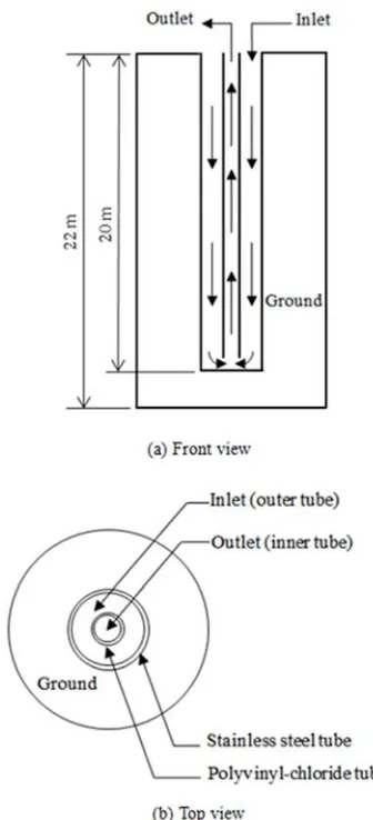
The numerical models consist of two-dimensional axisymmetric 20 m long double tube vertical GHE surrounded by 22 m depth and 6 m diameter ground soil. The schematic diagram of the double tube GHE model is shown in Fig. 1. The example pattern of mesh of double tube GHE and ground soil is shown in Fig. 2. The meshes consist of the working fluid water, GHE tubes and the ground soil. For all of the models, the thickness of annular inlet (outer) stainless steel (SS) tube and circular outlet (inner) polyvinyl chloride (PVC) tube were 5 mm and 4 mm respectively. Due to the axisymmetric of the problem domains, only half of the working fluid, GHE tube, and the ground soil were modeled in 2D to reduce the computational effort.
Figure 2. The example pattern of mesh of double tube GHE and ground soil.
In order to reduce the number of the total mesh and obtain an accurate result, the mesh around and inside the GHE tubes was densified, while the mesh size far away from the GHE tube was gradually enlarged. The geometrical configurations of all models are shown in Table 1 and thermo-physical properties of materials used in simulation models are listed in Table 2. Ground profile up to 15 m in depth is Clay and below 15 m is Sandy-clay [20]. Water was used as the heat transfer fluid.
Table 1. Geometric specification of GHE models.
Model Inlet (outer) tube diameter (mm)
Inlet (inner) tube diameter
(mm) Inlet tube thickness (mm) Outlet tube thickness (mm)
M1-1 130 40 5 4
M1-2 100 40 5 4
M1-3 70 40 5 4
M2-1 130 30 5 4
M2-2 100 30 5 4
M2-3 70 30 5 4
M2-4 60 30 5 4
M2-5 50 30 5 4
M3-1 130 20 5 4
M3-2 100 20 5 4
M3-3 70 20 5 4
M3-4 60 20 5 4
M3-5 50 20 5 4
M3-6 40 20 5 4
Table 2. Materials thermo-physical properties used in numerical model [17, 18].
Material name Density (kg/m3) Specific heat (J/kg- K) Thermal conductivity (W/m -K)
Stainless steel (inlet tube) 7817 460 13.8
Polyvinyl chloride (outlet tube) 1380 960 0.15
Clay 1700 1800 1.2
2.2. Numerical Method for Optimization
To optimization of double tube vertical GHE, numerical simulations were carried out by using the commercial CFD software ANSYS FLUENT 17.2 [21]. The governing equations are as follows [22]:
For 2D axisymmetric geometries, the continuity equation is given by
0 (1)
where ρ in density, t is time, x is axial coordinate, r is radial coordinate, vx is axial velocity and vr is radial velocity.
The axial and radial momentum conservation equations of 2D axisymmetric geometries are given by Eq. (2) and (3)
2 . (2)
2 . 2 ! " . (3)
where µ is viscosity, p is pressure and .
The energy equation is given by
# . $ % "&
'& $( (4)
where h is enthalpy, µt is turbulence viscosity, σtis constant.
In ground soil region, the energy transport equation given by
)* + . , - (5)
where ρs is density of soil, Cp is specific heat of soil, k is
thermal conductivity of soil and T is temperature.
The numerical simulations were carried out for laminar flow and turbulent flow considering three mass flow rates as 1, 7 and 35 lit/min. The SIMPLE algorithm was used for the velocity-pressure coupling. To describe the fluid flow field,
finite-volume formulation was used to solve the
Navier-Stokes equations. Since heat transfer fluid in the simulation models is incompressible fluid water, hence the Realizable k−ε model with standard wall functions was considered for the case of turbulent flow [23]. The models were simulated in the cooling mode for continuous 24 h operation by applying the physical and thermal properties of materials listed in Table 2.
2.3. Boundary and Initial Conditions
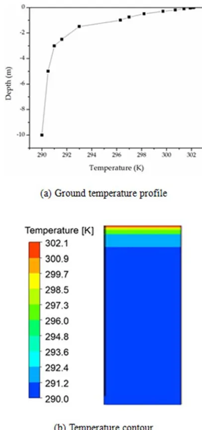
A constant and uniform temperature 302 K was applied to the top surface of the ground. At the bottom, a heat flux 65 mW/m2 [24] was used. The outer surface of ground at a distance 3.0 m from the center line was considered no heat flux. Ground temperatures variation up-to 10.0 m depth at different depth positions measured on July 1, 2016 in Saga
University, Japan is shown in Fig. 3(a). The ground temperature influenced strongly up-to level 5 m in depth by ambient temperature and below that ground temperature assumed to be constant of 290 K. For cooling mode of operation, the initial ground temperature was assumed to be similar with the ground temperature measured on July 1, 2016. Then the simulation models were initialized with the temperature profile shown in Fig. 3(a). After initialization, the temperature contour is shown in Fig. 3(b). The inlet water temperature was set to 300 K; the inlet and outlet were considered as the velocity-inlet and outflow. Three mass flow rates 1, 7 and 35 lit/min were considered and the inlet velocity magnitude for each model was set corresponding to mass flow rates of 1, 7 and 35 lit/min. Corresponding to these mass flow rates, the simulation conditions and the fluid flow regimes are summarized in Table 3.
Table 3. Simulation conditions and fluid flow regime for all of the simulation models.
Case Mass flow rate (lit/min)
Inlet water temperature (K)
Reynolds number in inlet tube
Reynolds number in outlet tube
Flow regime in inlet tube
Flow regime in outlet tube
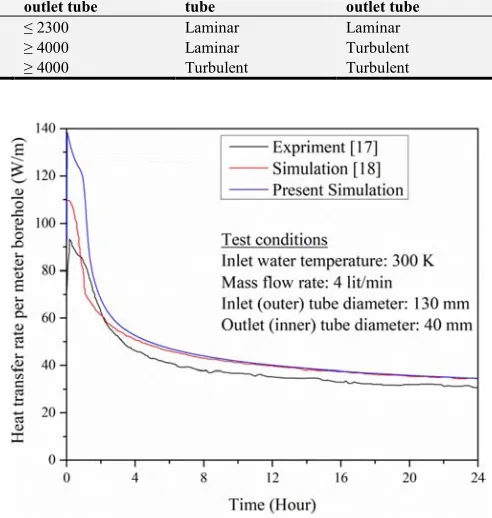
1 1 300 ≤ 2300 ≤ 2300 Laminar Laminar
2 7 300 ≤ 2300 ≥ 4000 Laminar Turbulent
3 35 300 ≥ 4000 ≥ 4000 Turbulent Turbulent
2.4. Mesh Elements Independence Test
To perform the grid independence test, four sets of grid such as 16635, 24510, 46645 and 122413 elements were considered. The model M1-1 was simulated with mass flow rate 2 lit/min, inlet water temperature 300 K. After 24 h operation, the outlet temperatures were 295.70 K, 295.67 K, 295.64 K and 295.61 K respectively for 16635, 24510, 46645 and 122413 elements. For all of the elements number, outlet temperature after 24 h operation very closed to each other. With increasing the elements number, outlet temperature little change. Therefore 46645 grid system was used in this study.
2.5. Model Validation
Comparison between simulation and experimental results are needed for better understanding of acceptance of the numerical results. To confirm reliability of numerical simulation models implemented in present study, the heat transfer rate obtained from present simulation results were compared with experimental and numerical results of Jalaluddin et al. [17, 18]. For comparison with previous results, the assumptions used i.e., (i) hybrid mesh generation method; (ii) CFD code; (iii) similar parameters; (iv) similar boundary conditions and initial conditions; (v) experimental data in site. In the previous test [17, 18], the inlet and outlet tube diameter were 130 mm and 40 mm; GHE length was 20 m; the inlet water temperature was 300 K; mass flow rates of water were 2, 4 and 8 lit/min; the operation time was 24 h and materials properties were same as listed in Table 2. The heat transfer rates of present model M1-1 were compared with previous [17, 18] heat transfer rates under above mentioned similar conditions. The average heat transfer rates for 2, 4 and 8 lit/min were 36.9, 49.6 and 54.8 W/m respectively [17, 18]. On the other hand in present simulation model M1-1, the corresponding heat transfer rates are 37.7, 51.7 and 55.3 W/m respectively for 2, 4 and 8 lit/min. The deviations of heat transfer rate are 2.1, 4.2 and 0.9% respectively for mass flow rate 2, 4 and 8 lit/min. For simplicity, Fig. 4 shows the comparison of heat transfer rate per meter borehole length of present simulation result and results from Jalaluddin et al. [17, 18] for mass flow rate 4 lit/min. The present numerical result in Fig. 4 shows the similar trend with Jalaluddin’s experimental and numerical results and deviation is within 4.2%. This confirmed that the good agreement of simulation model results with previous results.
Figure 4. Validation of present numerical model with the data from Jalaluddin et al. [17, 18] for mass flow rate 4 lit/min.
3. Results and Discussion
3.1. Selection of Inlet and Outlet
Before starting the optimization simulation of double tube vertical GHEs, it is necessary to decide inlet in either inner tube or outer tube is more effective for heat transfer. Preliminary simulation was done for model M1-1 (outer annular tube diameter 130 mm and inner circular tube diameter 40 mm) by alternating the inlet and outlet in outer tube and inner tube. Inlet water temperature was 300 K, mass flow rates were 1 and 4 lit/min and boundary and initial conditions were similar described in section 2.3. It was observe that the average heat transfer rates in 24 h operation are 23.8 and 49.4 W/m respectively for the mass flow rates of 1 and 4 lit/m when we considered inlet in outer annular tube and outlet in inner circular tube. On the other hand if we considered inlet in inner circular tube and tube in outer annular pipe the average heat transfer rates are 20.6 and 43.4 W/m respectively for the mass flow rates 1 and 4 lit/m. So inlet in outer annular tube and outlet at inner circular tube has been chosen for simulation of models.
3.2. Heat Transfer Rate
Heat transfer rates were calculated to investigate the thermal performance of the GHEs. Heat transfer rate can be calculated by follow:
where m is the mass flow rate (kg/s), Cp is the specific heat (J/kg K), and ∆T is the temperature difference between the inlet and outlet of circulated water (K). Then heat transfer rate per meter borehole depth is defined as follow:
q = Q/L (7)
where L is the length of the borehole.
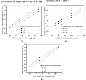
Heat transfer rate assessment in three criteria such as: (i)
laminar flow through both inlet and outlet tubes refereed as case 1; (ii) laminar flow through inlet tube, turbulent flow through outlet tube refereed as case 2; (iii) turbulent flow through both inlet and outlet tubes refereed as case 3. Fig. 5 shows the heat transfer rate per unit borehole length for all of the models in 24 h continuous operation and the average heat transfer rates of each flow rate for all of the models are summarized in Table 4.
Figure 5. Average heat transfer rate per meter borehole of the GHE models (a) Laminar flow through inlet and outlet tube @ 1 lit/min; (b) Laminar flow through inlet tube and turbulent flow through outlet tube @ 7 lit/min; (c) Turbulent flow through inlet and outlet tube @ 35 lit/min.
Table 4. Average heat exchange rates of each of the model for cases 1, 2 & 3.
Model Average heat transfer rate (W/m)
1 lit/min 7 lit/min 35 lit/min
M1-1 23.8 54.1 74.8
M1-2 22.5 48.5 64.0
M1-3 21.1 41.8 51.8
M2-1 24.2 55.5 76.1
M2-2 23.0 50.5 66.0
M2-3 21.6 44.5 55.6
M2-4 21.1 42.6 52.0
M2-5 20.6 40.6 47.5
M3-1 24.7 57.0 77.1
M3-2 23.5 52.6 69.0
M3-3 22.0 46.5 59.9
M3-4 21.5 44.5 56.2
M3-5 21.0 42.4 52.5
M3-6 20.4 40.0 47.2
From Fig. 5(a)-(c), it can be seen that heat transfer rate per meter borehole length increased with the increases of inlet tube diameter for a fixed outlet tube diameter. For example from Fig. 5(a), for the case 1 with inlet tube diameter 130 mm
transfer occurred with the increases overall size of the GHE which will increases the material cost and installation cost. On the other hand for a fixed inlet tube diameter, heat transfer rate increased with decreases of outlet tube diameter. For example in case 1 with fixed inlet tube diameter 130 mm, the average heat transfer rate was 24.7 W/m when outlet tube diameter 20 mm (model M3-1) and 23.8 W/m when outlet tube diameter 40 mm (model M1-1). This happened because of the contact surface area between water and outlet tube decreases with the decreases of outlet tube diameter. This reduces the heat transfer between inlet tube and outlet tube. Similarly for the cases 2 and 3, there is some enhancement of heat transfer occurred by reducing the outlet tube diameters for a fixed inlet tube diameter. So there is an opportunity to reduce material cost of double tube GHE by reducing the outlet tube diameter for a fixed inlet diameter tube.
3.3. Pressure Drop
The pressure drop through all of the models is shown in Fig. 6. In order to verify the pressure drop through GHE tubes due to water flow, pressure drop also calculated by using following equations:
∆4 5) 768 9 :
!
(8)
where ∆P is the pressure drop (Pa), fs is the friction factor, L is
the tube length (m), DH is the hydraulic diameter of tube (m), ρ
is the density of fluid (kg/m3), V is the fluid velocity (m/s).
For straight tube, friction factor can be calculated by Hagen–Poiseuille equation for laminar flow
5) =>;< (9)
and by Blasius equation for turbulent flow
5) =>?. ;@.!A (10)
Also pressure drop caused by sudden contraction when water enters in outlet tube from inlet tube can be calculated by:
∆4B :CD:E ! (11)
where Vo is the velocity in outlet tube and Vi is the velocity in inlet tube.
Then the total pressure drop through the GHE is calculated by
∆4F GH ∆4IJH> LM> ∆4FL H> I > ∆4B (12)
Fig. 6 also included the calculated values of pressure drops by using Eq. (12). The pressure drop through GHE tube increased with increase of flow rate and with the decrease of GHEs tube diameter. This indicates that increases of pump work of GSHP system. Table 5 summarized the simulated pressure drop through GHE models. From Fig. 6(a)-(c) it can be seen that the numerical pressure drops slightly higher than that of calculated pressure drops through GHE models.
Table 5. Pressure drop from numerical simulation of each of the model for cases 1, 2 & 3.
Model Pressure drop (Pa)
1 lit/min 7 lit/min 35 lit/min
M1-1 5.4 125 1498
M1-2 6.2 130 1537
M1-3 16.8 235 2907
M2-1 16.5 401 5897
M2-2 17.9 411 5981
M2-3 21.5 448 6815
M2-4 32.9 549 8110
M2-5 99.8 1233 20022
M3-1 79.1 2361 40001
M3-2 80.3 2374 40587
M3-3 83.4 2430 41252
M3-4 89.2 2503 42137
M3-5 96.2 2628 45683
M3-6 191.8 3802 65278
3.4. Optimization Evaluation
Based on the simulation results shown in Fig. 5 and summarized in Table 4, it was discussed in section 3.2 that the reduction of outlet tube diameter helps to improve the thermal performance of double tube vertical GHE. Also reduction of inlet tube diameter is possible considering small decreases of heat transfer rate at low mass flow rate especially in laminar flow (case 1 for example). In the laminar flow both in inlet tube and outlet tube with mass flow rate 1 lit/min (case 1), heat transfer rate decreased only 14% for the model M3-6 compare to the model M1-1. When water flow is laminar in inlet tube and turbulent in outlet tube with mass flow rate 7 lit/min (case 2), the heat transfer rate decreased 26% for the model M3-6 compare to the model M1-1. The corresponding decreased of heat transfer rate is 36% when turbulent flow both in inlet and outlet tube with the mass flow rate 35 lit/min (case 3). Thus with increasing the mass flow rate from laminar to turbulent, the decreasing rate of heat transfer rate increases when compared between the models M1-1 and M3-6. Based on the model M3-6, with increasing the mass flow rate from laminar to turbulent, the decreasing rate of heat transfer rate similarly increased for all other models. Even if the heat transfer rate decreased 14% in the case 1 for model M3-6 compare to model M1-1, the inlet tube diameter can be reduced from 130 mm to 40 mm and outlet tube diameter from 40 mm to 20 mm. On the other hand the heat transfer rate decreased 16% in the case 1 for model M3-6 compare to model M2-1, the inlet tube diameter can be reduced from 130 mm to 40 mm and outlet tube diameter from 30 mm to 20 mm. Thus it is better to reduce the outlet (inner) tube diameter for a fixed inlet (outer) tube diameter on the basis of heat transfer rate. Also in case 1, if we compare between model M3-1 and M3-6, the heat transfer rate decreased 17% but we can reduce the inlet tube diameter from 130 mm to 40 mm with fixed outlet tube diameter 20 mm. The heat transfer rate decreased 13% for model M3-6 compare to model M3-2 in case 1, but reduction of the inlet tube diameter from 100 mm to 40 mm is possible with fixed outlet tube diameter 20 mm. Similarly based on the model M3-6, for all other models from M3-1 to M3-5, with
decreasing the inlet (outer) tube diameter the decreasing rate of heat transfer rate gradually decreased.
It is obvious that with increases of mass flow rate, heat transfer rate will also be increased. However, from Figs. 5 and 6 and Tables 4 and 5, any improvement of heat transfer or reductions of the size of GHE are always included a penalty of pressure drop. From Fig. 6 and Table 5, the pressure drops of all models are in low range (5.4 to 191.8 Pa) for the case 1 when inlet and outlet tube flow was in laminar. Pressure drop significantly increased when flow rate increased from 1 lit/min (both inlet and outlet tube flow laminar) to 7 lit/min (inlet tube flow laminar and outlet tube flow turbulent). And pressure drops are very high when both inlet and outlet tube flow in turbulent (case 3 @ 35 lit/min). Pressure drops also increased with decrease of inlet and outlet tube diameter of GHE models for a fixed mass flow rate.
In order to achieve an energy savings by reducing the inlet and outlet diameter of double tube vertical GHE, the balance between heat transfer and pressure drop needed to examine. For instance, for model M1-1, the heat transfer rate increased 2.3 times and 3.1 times respectively when mass flow rate increased from 1 lit/min to 7 lit/min and 1 lit/min to 35 lit/min. The pressure drop increased 23.1 times and 277.4 times respectively corresponding increases of mass flow rate increased from 1 lit/min to 7 lit/min and 1 lit/min to 35 lit/min. Similar characteristics of increased of the heat transfer rate and pressure drop can be observed from Table 4 and 5 for all of the models. So it is better to operate the double tube vertical GHE in laminar flow condition which will save high pump work as well as save selection of high capacity pump and operating cost. In this case just we have to concern about small decreasing rate of heat transfer rate. For instance, in the case of laminar flow both in inlet tube and outlet tube with mass flow rate 1 lit/min (case 1), the pressure drop increased 2.4 times and heat transfer rate decreased 1.2 times for model M3-6 compared to model M3-1. Importance of this penalty of pressure drop and heat transfer rate reduced the inlet tube diameter from 130 mm to 40 mm fixed outlet tube diameter. Therefore, the heat transfer rate and pressure drop are related to both the mass flow rate (Reynolds number) and size of the GHE, it is best option to install smaller diameter (M3-6 for example) double tube vertical GHE and operate in laminar flow condition.
The coefficient of performance (COP) improvement criterion proposed by Jalaluddin and Miyara [16] has been assumed to evaluate the energy balance between heat transfer rate and pressure drop. The COP improvement criterion was calculated from the following equation:
NO8
N8
:∆ N8
∆ O
∆ > 0 (13)
where QH is heating rate (W/m), QʹH is increases of heating
M2-3, M3-3 and M3-6 using similar boundary conditions and properties of U-tube GHE [16]. We considered lower size double tube GHE. Because, if the lower size GHEs improve the COP criterion, than other higher size GHEs obviously will improve the COP criterion. By using Eq. (13), the COP improvement criterions are listed in Table 6. The COP improvement criterions were analyzed on the basis of U-tube GHE data with flow rate of 2 lit/min [16].
In the case of U-tube GHE [16], the minimum borehole diameter was 86 mm. In the present double tube GHE, if we
select inlet (outer) tube diameter 70 mm, then borehole diameter required 80 mm because thickness of tube is 5 mm. And for other lower size inlet tube GHEs, borehole diameter will also be lowered. But COP improvement criterions for double tube in Table 6 have shown always positive. The positive value of Eq. (13) in Table 6 indicates net COP improved. Within the present simulation models, reduced size of double tube vertical GHE effective for GSHP system even if pressure drop increased and heat transfer rate little decreased with the size reduction.
Table 6. The COP improvement criterion defined in Eq. (8) with mass flow rate 2 lit/min.
Model QDouble tube QH [14] QʹH V ∆PDouble tube ∆P [14] ∆Pʹ Eq. (13)
W/m m3/s Pa/m
M1-3 20.0 14.1 5.9 3.3333E-5 2.3 3.1 -0.8 0.42
M2-3 20.2 14.1 6.1 3.3333E-5 3.1 3.1 0.0 0.43
M3-3 20.5 14.1 6.4 3.3333E-5 9.4 3.1 6.3 0.45
M3-6 17.3 14.1 3.2 3.3333E-5 19.2 3.1 16.1 0.23
3.5. Effect of GHE Materials on Heat Transfer
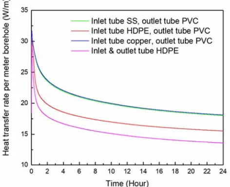
High density polyethylene (HDPE) tube is usually used in installation of GHEs. However, copper tubing has been successfully used in some applications since copper tube has a very high thermal conductivity [4]. The effect of different tube materials on heat transfer rate with mass flow rate 1 lit/min was investigated and compared as shown in Fig. 7. Inlet (outer) tube with HDPE (density of 955 kg/m3, specific heat of 2300 J/kg·K, thermal conductivity of 0.461 W/m·K), copper (density of 8978 kg/m3, specific heat of 381 J/kg·K, thermal conductivity of 387.6 W/m·K) and stainless steel (SS) were considered. Outlet (inner) tube was considered as polyvinyl chloride (PVC) tube which was common for HDPE, copper and stainless steel inlet tube. Properties of SS and PVC have given in Table 2.
Figure 7. Effect of GHE materials on heat transfer rate.
The average heat transfer rates in 24 h continuous operation were 20.4 W/m for inlet tube SS and outlet tube PVC; 20.6 W/m for inlet tube copper and outlet tube PVC; 17.3 W/m for inlet tube HDPE and outlet tube PVC and 15.3
W/m for both inlet and outlet tube HDPE. The average heat transfer rate for both SS and copper tube GHE are almost similar. The practical viewpoint is that even though the thermal conductivity of copper is very higher than that of SS, the heat transfer is dominated by surrounding ground soil around the GHE. The GHE with HDPE inlet tube and PVC outlet tube has 13% higher heat transfer rate in contrast GHE with HDPE in both inlet and outlet tube in 24 h operation. The reason is less heat interaction between inner and outer tube water when lower thermal conductivity material PVC was used as inner tube. Though the heat transfer rate is higher of copper tube and SS tube compared to HDPE tube, but copper tube and SS tube must have to be protected from corrosion in terms durability and corrosion resistance. Even though copper tube and SS tube protected from corrosion by using thin coating of corrosion resistance material, the high cost of copper and SS compare HDPE and PVC should be considered. And also the overall thermal conductivity of thin coated copper tube and SS tube necessarily need to calculate before selection.
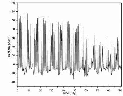
3.6. Effect of Long Time Operation on Ground Soil Temperature Around GHE
1.25 m after 60 days and 1.28 after 90 days respectively in radial direction. On the other hand at 15 m depth was about 1.05 m after 30 days, 1.10 m after 60 days and 1.13 after 90 days respectively in radial direction. So it is possible to install multiple double tube vertical GHE placing at 2.0 m lateral
distance. But it depends on the operation time and mass flow rate. Also thermal interference should be considered especially in upper region near ground surface which can be analyzed by 3D simulation.
Figure 8. Ground surface heat flux measured Saga University, Japan from July 1, 2016 to September 30, 2016.
4. Conclusion
In this study, the tow-dimensional axisymmetric transient heat transfer of double tube vertical GHE has been studied numerically. Before optimization, the model was validated with previous experimental and numerical results. The results of a numerical study of optimization of double tube vertical GHEs have been done by considering heat transfer rates and pressure drops. Effect of the different materials on heat transfer also discussed. Long time operation was discussed to observe the ground temperature variation around GHE at several radial and vertical distances.
The double tube vertical GHEs are more effective in laminar flow condition considering balance between heat transfer and pressure drop. Since in laminar flow region, pressure drop is not significantly high for our simulation models, if operate the vertical GHE in laminar flow condition, it is possible to reduce the inlet and outlet diameter of GHEs. The heat transfer rate decreased only 17.4% but the inlet (outer) tube diameter can be reduced from 130 mm to 40 mm with fixed outlet (inner) tube diameter 20 mm. Heat transfer rate can be enhanced by reducing the outlet tube diameter for a fixed inlet tube diameter but pressure drop also increased. The heat transfer rate and pressure drop are related to both the mass flow rate (Reynolds number) and size of the GHE, it is good choice to install small size (inlet diameter 40 mm and outlet diameter 20 mm for example) double tube vertical GHE and operate in laminar flow condition. This reduced size GHE and laminar flow operation will save overall cost of installation and high pumping work as well as save selection of high capacity pump and operating cost. Long time operation suggests the possibility of installation of multiple double tube vertical GHE placing at 2.0 m lateral distance.
Since the heat transfer is dominated by ground around GHE, copper tube and stainless steel showed same almost same effect on heat transfer rate though the thermal conductivity of copper is 28 times higher than stainless steel. Furthermore HDPE is usually used in installation of GHE, the present study suggests that in double tube GHE, inlet (outer) tube with HDPE and outlet (inner) tube with PVC is more effective than HDPE tubes use both in inlet and outlet.
Acknowledgements
This work was sponsored by the project on "Renewable energy-heat utilization technology & development project" of New Energy and Industrial Technology Development Organization (NEDO), Japan.
References
[1] J. E. Bose, M. D Smith, and J. D. Spitler, “Advances in ground source heat pump systems-An international overview,” Proceedings of the Seventh International Energy Agency Heat Pump Conference, 2002, Beijing, China, pp. 313-324. [2] I. Sarbu, and C. Sebarchievici, “General review of ground
source heat pump systems for heating and cooling of buildings,” Energy and Buildings, 2014, vol. 70, pp. 441-454.
[3] H. Esen, M. Inalli, “Thermal response of ground for different depths on vertical ground source heat pump system in Elazig, Turkey,” Journal of the Energy Institute, 2009, vol. 82 (2), pp. 95-101.
[4] S. P. Kavanaugh, and K. Rafferty, “Ground-source heat pumps, design of geothermal systems for commercial and institutional buildings,” 1997, Atlanta: ASHRAE.
[5] D. Banks, “An introduction to thermo geology: ground source heating and cooling,” 2008, Wiley-Blackwell.
[6] H. Yang, P. Cui, and Z. Fang, “Vertical-borehole ground-coupled heat pumps: a review of models and systems,” Applied Energy, 2010, vol. 87 (1), pp. 16-27.
[7] M. Khan, “Modeling, simulation and optimization of ground source heat pump systems,” M. S. Thesis, Oklahoma State University, 2004, USA.
[8] V. Khalajzadeh, G. Heidarinejad, and J. Srebric, “Parameters optimization of a vertical ground heat exchanger based on response surface methodology” Energy and Buildings., 2011, vol. 43 (6), pp. 1288–1294.
[9] S. Sanaye, and B. Niroomand, “Thermal-economic modeling and optimization of vertical ground-coupled heat pump,” Energy Conversion and Management, 2009, vol. 50 (4), pp. 1136-1147. [10] S. Huang, Z. Ma, and F. Wang, “A multi-objective design
optimization strategy for vertical ground heat exchangers,” Energy and Buildings, 2015, vol. 87, pp. 233-242.
[11] J. E. Bose, J. D. Parker, and F. C. McQuiston, “Design/Data manual for closed-loop ground coupled heat pump systems,” Atlanta, ASHRAE, 1985.
[12] C. Zhang, S. Hu, Y. Liu, and Q. Wang, “Optimal design of borehole heat exchangers based on hourly load simulation,” Energy, 2016, vol. 116, pp. 1180-1190.
[13] W. Zhang, H. Yang, L. Lu, and Z. Fang, “The heat transfer analysis and optimal design on borehole ground heat exchangers,” Energy Procedia, 2014, vol. 61, pp. 385 – 388. [14] X. Y. Li, T. Y. Li, D. Q. Qu, and J. W. Yu, “A new solution for
thermal interference of vertical U-tube ground heat exchanger for cold area in China,” Geothermics, 2017, vol. 65, pp. 72-80. [15] G. Florides, E. Theofanous, I. Iosif-Stylianou, S. Tassou, P. Christodoulides, Z. Zomeni, E. Tsiolakis, S. Kalogirou, V. Messaritis, P. Pouloupatis, and G. Panayiotou, “Modeling and assessment of the efficiency of horizontal and vertical ground heat exchangers,” Energy, 2013, vol. 58, pp. 655–663. [16] Jalaluddin, and A. Miyara, “Thermal performance and pressure
drop of spiral-tube ground heat exchangers for ground-source heat pump,” Applied Thermal Engineering, 2015, vol. 90, pp. 630-637. [17] Jalaluddin, A. Miyara, K. Tsubaki, S. Inoue, and K. Yoshida, “Experimental study of several types of ground heat exchanger using a steel pile foundation,” 2011, Renewable Energy, vol. 36, pp. 764-771.
[19] JSME Data Book: Heat Transfer, fifth ed. The Japan Society of Mechanical Engineers, 2009, (in Japanese).
[20] A. Bejan, and A. D. Kraus, “Heat transfer handbook,” John Wiley & Sons, Inc., New Jersey, 2003.
[21] ANSYS® Academic Research, Release 17.2.
[22] ANSYS® Academic Research, Release 17.2, Help System, Fluent Theory Guide, ANSYS, Inc.
[23] ANSYS® Academic Research, Release 17.2, Help System, Fluent User’s Guide, ANSYS, Inc.
![Table 2. Materials thermo-physical properties used in numerical model [17, 18].](https://thumb-us.123doks.com/thumbv2/123dok_us/9891858.1976715/3.595.159.441.86.426/table-materials-thermo-physical-properties-used-numerical-model.webp)