V. Sridhar
et al
, International Journal of Computer Science and Mobile Applications,
Vol.2 Issue. 12, December- 2014, pg. 01-07 ISSN: 2321-8363
©2014, IJCSMA All Rights Reserved, www.ijcsma.com 1
REDUCTION OF HARMONICS IN SOLAR POWER
GENERATION SYSTEM BY USING FIVE LEVEL INVERTER
V. Sridhar
1G. Laxminarayana
2M.Tech
1,2Assistant Professor
2Aurora’s Engineering College
1,2Abstract:
A five-level inverter implemented in this paper for injecting of the real power of the solar power into the grid to eliminate the switching losses, harmonic distortion, and electromagnetic interference caused by the switching operation. Five level inverter can be designed with combination of two dc capacitors which are connected to the dual-buck converter and single phase H-bride converter. The output voltage of the dual-buck converter supplies to the full-bridge inverter. The switches of the full-bridge inverter are triggered in low frequency synchronous with the utility voltage to convert the output voltage of the dual-buck converter to a five-level ac voltage. The output current of the five-level inverter is controlled by producing a sinusoidal current in phase with the utility voltage to inject into the grid this system can be designed by matlab/simulink software.
Key Words: Harmonic distortion, inverters, electromagnetic interference dual-buck converter and power electronics.
1
. INTRODUCTIONV. Sridhar
et al
, International Journal of Computer Science and Mobile Applications,
Vol.2 Issue. 12, December- 2014, pg. 01-07 ISSN: 2321-8363
©2014, IJCSMA All Rights Reserved, www.ijcsma.com 2
are switched in high frequency to generate a three-level voltage and balance the two input dc voltages. The power electronic switches of the full-bridge inverter are switched in low frequency synchronous with the utility to convert the output voltage of the dual-buck converter to a five-level ac voltage. Therefore, the switching power loss, harmonic distortion, and electromagnetic interference caused by the switching operation of power electronic devices can be reduced, and the control circuit is simplified. Besides, the capacity of output filter can be reduced. A hardware prototype is developed to verify the performance of the developed renewable power generation system.
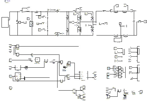
1.1 circuit description
Five-level inverter applied to a photovoltaic power generation system. As can be seen, it is configured by a solar cell array, a dc–dc converter, a five-level inverter, two switches, and a digital signal processor (DSP)-based controller. Switches SW1 and SW2 are placed between the five-level inverter and the utility, and they are used to disconnect the photovoltaic power generation system from the utility when islanding operation occurs. The load is placed between switches SW1 and SW2 . The output of the solar cell array is connected to the input port of the dc–dc converter. The output port of the dc–dc converter is connected to the five-level inverter. The dc–dc converter is a boost converter, and it performs the functions of maximum power point tracking (MPPT) and boosting the output voltage of the solar cell array.
Fig.1. Circuit topology of the developed solar power generation system.
V. Sridhar
et al
, International Journal of Computer Science and Mobile Applications,
Vol.2 Issue. 12, December- 2014, pg. 01-07 ISSN: 2321-8363
©2014, IJCSMA All Rights Reserved, www.ijcsma.com 3
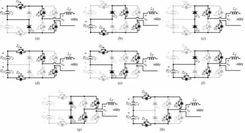
1.2 principle and modes of operation of five level inverter.
Fig. 3. Operation modes of the five-level inverter. (a) Mode 1. (b) Mode 2. (c) Mode 3. (d) Mode 4. (e) Mode 5.
(f) Mode 6. (g) Mode 7. (h) Mode 8.
The operation of this five-level inverter can be divided into eight modes. Modes 1–4 are for the positive half-cycle, and modes 5–8 are for the negative half-cycle. Fig. 3 shows the operation modes of five-level inverter. As can be seen, the power electronic switches of the full-bridge inverter are switched in low frequency and synchronously with the utility voltage to convert the dc power into ac power for commutating. As seen in Fig. 3(a)–(d), the power electronic switches S4 and S7 are in the ON state, and the power electronic switches S5 and S6 are in the OFF state during the positive half-cycle. On the contrary, the power electronic switches S4 and S7 are in the OFF state, and the power electronic switches S5 and S6 are in the ON state during the negative half-cycle. Since the dc capacitor voltages VC2 and VC3 are balanced by controlling the five-level inverter, the dc capacitor voltages VC2 and VC3 can be represented as follows:VC2 = VC3 =1/2Vdc. The operation modes of this five-level inverter are stated as follows.
Mode 1: Fig. 2(a) shows the operation circuit of mode 1.
The power electronic switch of the dual-buck converter S2 is turned ON and S3 is turned OFF. DC capacitor C2 is discharged through S2, S4 , the filter inductor, the utility, S7 , and D3 to form a loop. Both output voltages of the dual-buck converter and five-level inverter are Vdc/2. Mode 2: Fig. 2(b) shows the operation circuit of mode 2. The power electronic switch of the dual-buck converter S2 is turned OFF and S3 is turned ON. DC capacitor C3 is discharged throughD2, S4 , the filter inductor, the utility, S7 , and S3 to form a loop. Both output voltages of the dual-buck converter and five-level inverter are Vdc/2. Mode 3: Fig. 2(c) shows the operation circuit of mode 3. Both power electronic switches S2 and S3 of the dual-buck converter Both power electronic switches S2 and S3 of the dual-buck converter are turned OFF. The current of the filter inductor flows through the utility, S7, D3, D2, and S4 . Both output voltages of the dual buck converter and five-level inverter are 0. Mode 4: Fig. 3(d) shows the operation circuit of mode 4. Both power electronic switches S2 and S3 of the dual-buck converter are turned ON.DCcapacitorsC2 andC3 are discharged together through S2, S4 , the filter inductor, the utility, S7 , and S3 to form a loop. Both output voltages of the dual-buck converter and five-level inverter are Vdc. Modes 5–8 are the operation modes for the negative half cycle. The operations of the dual-buck converter under modes 5–8 are similar to that under modes 1–4, and the dual-buck converter can also generate three voltage levels Vdc/2, Vdc/2, 0, and Vdc, respectively. However, the operation of the full-bridge inverter is the opposite. The power electronic switches S4 and S7 are in the OFF state, and the power electronic switches S5 and S6 are in the ON state during the negative half-cycle. Therefore, the output voltage of the five-level inverter for modes 5–8 will be −Vdc/2, −Vdc/2, 0, and −Vdc, respectively.
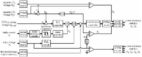
1.3. control block diagram
V. Sridhar
et al
, International Journal of Computer Science and Mobile Applications,
Vol.2 Issue. 12, December- 2014, pg. 01-07 ISSN: 2321-8363
©2014, IJCSMA All Rights Reserved, www.ijcsma.com 4
and injecting it into the utility, balancing two dc capacitor voltages VC2 and VC3 , and detecting the islanding operation. The dc–dc converter boosts the output voltage of the solar cell array and performs the MPPT to extract maximum output power of the solar cell array. The controllers of both the dc–dc converter and the five-level inverter are explained as follows.
Fig. 4 shows the control block diagram of five-level inverter. In the operation of the five-level inverter, the dc bus voltage must be regulated to be larger than the peak voltage of the utility, and the dc capacitor voltages of C2 and C3 must be controlled to be equal. Besides, the five-level inverter must generate a sinusoidal current in phase with the utility voltage to be injected into the utility. As seen in Fig. 6, the voltages of dc capacitors C2 and C3 are detected and then added to obtain a dc bus voltage Vdc. The added result is subtracted from a dc bus setting voltage Vdc set. The dc bus setting voltage Vdc set is larger than the peak voltage of the utility. The subtracted result is sent to a P-I controller. An islanding detection is also incorporated into the control of the five-level inverter. The concept of this islanding detection was proposed by authors. However, it will not be addressed in this paper. As seen in Fig. 4, the utility current is detected and sent to an RMS detection circuit. The output of the RMS detection circuit is sent to a hysteresis comparator that contains a low
threshold value and a high threshold value. If the RMS value of the utility current is smaller than the low threshold value, the output of the hysteresis comparator is high, meaning the condition of islanding operation or power balance occurs. On the contrary, the output of the hysteresis comparator is low when the RMS value of the utility current is larger than the high threshold value, meaning the utility is normal. The output of the hysteresis comparator is sent to a signal generator. The output signal of the signal generator is an islanding control signal Sa . with the detected utility voltage. The complementary square signals are the control signals of the power electronic switches of the full-bridge inverter. As mentioned earlier, only two power electronic switches S2 or S3 in the five-level inverter should be switched in high frequency, and only one of them is switched in high frequency at any time, and the voltage level of every switching is Vdc/2. Therefore, the five-level inverter can reduce
the switching loss effectively.
Fig.4. Control block diagram of five-level inverter.
V. Sridhar
et al
, International Journal of Computer Science and Mobile Applications,
Vol.2 Issue. 12, December- 2014, pg. 01-07 ISSN: 2321-8363
©2014, IJCSMA All Rights Reserved, www.ijcsma.com 5
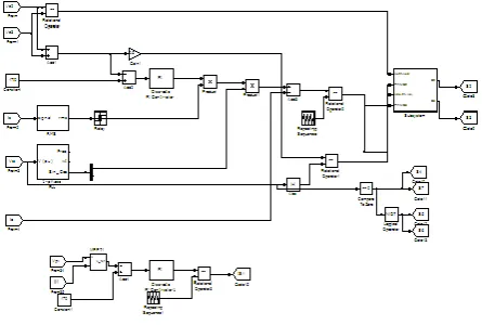
Fig 6 simulation diagram of control strategyTABLE I
COMPARISON OF FIVE-LEVEL INVERTERS
2. Simulation Results
Fig 5.Simulation results of the five-level inverter. (a) Utility voltage. (b) Output current of the five-level inverter. (c) DC capacitor voltage VC 2 .
V. Sridhar
et al
, International Journal of Computer Science and Mobile Applications,
Vol.2 Issue. 12, December- 2014, pg. 01-07 ISSN: 2321-8363
©2014, IJCSMA All Rights Reserved, www.ijcsma.com 6
Fig 6. .Simulation results for full-bridge inverter of the five-level inverter.(a) Output current of the full-bridgeinverter io . (b) Input current of the full bridge inverter idc . (c) Driver signal of S4 . (d) Driver signal of S5 .
Fig.7. Simulation results of the five-level inverter. (a) Utility voltage.
(b) Output voltage of the full-bridge inverter. (c) Output voltage of the dual buck converter.
3. CONCLUSIONS
A photovoltaic power generation system with a five-level inverter is developed. The five-level inverter can perform the functions of regulating the dc bus voltage, converting solar power to ac power with sinusoidal current and in phase with the utility voltage, balancing the two dc capacitor voltages, and detecting is landing operation. From the grid single phase diode rectifier with R-L load developed using matlab/ simulink software.
REFERENCES
[1]. Safety of Power Converters for Use in Photovoltaic Power Systems—Part2: Particular Requirements for Inverters, IEC 62109-2, Ed.1, 2011.
[2]. G. P. Adam, S. J. Finney, B. W. Williams, and M. T. Mohammed, “Twolevel of a diode-clamped multilevel inverter,” in Proc. IEEE Int.Symp. Ind. Electron., Jul. 2010, pp. 1137–1142.
V. Sridhar
et al
, International Journal of Computer Science and Mobile Applications,
Vol.2 Issue. 12, December- 2014, pg. 01-07 ISSN: 2321-8363
©2014, IJCSMA All Rights Reserved, www.ijcsma.com 7
[4]. G. J. Yu, Y. S. Jung, J. Y. Choi, and G. S. Kim, “A novel two-mode MPPT control algorithm based on comparative study of existing algorithms,”Solar Energy, vol. 76, no. 4, pp. 455–463, 2004.
[5] B. R. Lin and C. L. Huang, “Implementation of a Shunt-series compensator for nonlinear and voltage sensitive load,” in Proc. IEEE PowerElectron. Motion Control Conf., 2006, pp. 1–5.
[6] U. S. Selamogullari, D. A. Torrey, and S. Salon, “A systems approach for a stand-alone residential fuel cell power inverter design,” IEEE Trans.Energy Convers., vol. 25, no. 3, pp. 741–749, Sep. 2010.
BIOGRAPHIES