ISSN : 2581-7175 ©IJSRED: All Rights are Reserved Page 282
Experimental Study of Flexural Behaviour on Ferrocement
Concrete Beam
R.Vinoth
PG Scholar, M.E-StructuralEngineering, Department of CivilEngineering, Star Lion College Of Engineering And Technology, Manankorai, Thanjavur, Tamilnadu-614206.
---
************************
---ABSTRACT
Ferrocement is a form of reinforcement that differs from conventional reinforcement primarily by the manner in which the reinforcing elements are dispersed and arranged. The well distributed and aligned reinforcement has made ferrocement to behave like steel plates. As concrete is weak in tension the tensile stresses in flexural member is resisted by steel reinforcement. Hence in this project presents about an experimental investigation done on beam prototype made of reinforced concrete overlaid by a thin section of ferrocement under the main reinforcement. The major parameter studied in this project were type of ferrocement varied in spacing of interlocks. The entire beams prototypes were tested using two point loading system. Test results clearly indicate that the use of ferrocement layers as an additional reinforcement significantly enhances the flexural strength and cracking behaviour. Obtained results are compared with the control specimen. The test results show that the use of ferrocement with closely spacing provides the flexural strength and decreases the crack width among those concrete beam specimens. The results obtained from this work is expected to be useful in .determining the strength and crack width.
Key words: ferrocement, Flexural strength, concrete beam, crack width, reinforcement
---
************************
---1. INTRODUCTION
1.1 Definition of Ferro cement
Ferro cement is a thin walled concrete commonly constructed of hydraulic cement mortar reinforced with closely spaced layers of continuous and relatively small wire mesh. The mesh may be of metallic or other suitable materials.
Background:Ferro cement is one of the
earliest versions of reinforced concrete, however, it’s design has been mostly empirical and formal design guides have not been developed as they have been for more traditional reinforced concrete.
In the earthquake-resistant design of
structures, overstrength and ductility are key factors that influence safety. Ductility of the whole structure depends on the ductility of each individual member, for example: beams, beams, or floors. It also depends on the configuration of the structure. The appearance of cracks is quite common in structures that survive an earthquake. Some cracks may be cosmetic in nature and do not need any special attention. Nevertheless, often they show sufficient damage to require retrofit strengthening. Repairing and retrofitting concrete structures has become quite common in the construction industry due to the financial benefits, whether in terms of direct or in-direct
ISSN : 2581-7175 ©IJSRED: All Rights are Reserved Page 283
costs, compared to the alternative of demolition and total or partial re-construction. Various materials have been used for repair and strengthening, for example steel bar and plate, fiber reinforced polymers (FRP) and Ferro cement. For this study, the author used Ferro cementbeam and strengthen reinforced concrete using Ferro cement jacket beams subjected to staticand cyclic loading. The performance of the
strengthened beams was compared with
equivalent unaltered reinforced concrete and Ferro cementbeams.
According to the ACI Committee 549 (ACI, 1988), Ferro cement is a type of thin wall reinforced concrete commonly constructed of hydraulic cement mortar reinforced with closely spaced layers of continual and relatively small size wire mesh. This study investigates the use of Ferro cement for retrofitting existing reinforced concrete structures as well as its use as a construction material for new structures in seismically active zones.
Natural disasters such as earthquakes, tornadoes and tsunami threaten the integrity of civil infrastructures and safety of their uses. A large number of existing reinforced concrete buildings and other structures typically have not sufficient capacity to resist the forces during such catastrophes. In order to guarantee the safety of the people, the older structures need to be repaired and strengthened to prevent their collapse. Efficient methods are needed to be developed for structures repair and strengthening. The ageing of the nation’s infrastructure in a tight economic environment has necessitated the search for innovative and cost effective solutions. In recent years, the use of Ferro cement laminate has become a subject of great interest in structural community. Several studies had been focused on the use of externally bonded Ferro cement laminates to reinforce existing structures in need of strengthening. In general Ferro cement is considered as a highly versatile form of
composite material made of cement mortar and layers of wire mesh or similar small diameter steel mesh closely bound together to create a stiff structural form. This material, which is a special form of reinforced concrete, exhibits behaviour so different from conventional reinforced concrete in performance, strength and potential application it must be classed as a separate material. In rationally designed Ferro cement structures, the reinforcement consists of small diameter wire mesh in which the proportion and distribution of the reinforcement are made uniform by spreading out the wire mesh throughout the thickness of the element. This distribution of achieving improvements in many of the engineering properties of the material such as fracture, tensile and flexural strength,
toughness, fatigue resistance and impact
resistance but also provide advantages and novelty of the concept have stimulated what is now considered a worldwide interest in the use of Ferro cement.
ISSN : 2581-7175 ©IJSRED: All Rights are Reserved Page 284
1.2AIMS AND OBJECTIVES
The aim of this research project is to improve the knowledge and understanding of the behavior of Ferro cement short beams under combination loading and from this produce non-dimensional charts that can be used for design. The objective
A literature reviewer will be conducted to understand the current state of knowledge and to investigate whether information from similar applications is suitable for adaptation to the use with Ferro cement.
A number of experimental tests will be designed and conducted to provide information for, and validation of, the finite element model with respect to static loading and to cyclic loading.
Finite element model will be proposed to investigate the test specimens and to perform parametric studies with regard to the main properties of both the base beams and the Ferro cement strengthening.
Non-dimensional charts will be presented based on the above study to the ACI Committee 549 for potential inclusion into the Design Guide for Ferro cement.
1.3FERROCEMENT: DEFINITION AND
HISTORY
Ferro cement is defined by the American Concrete Institute (ACI) Committee 5in their “State of the Art Report” (ACI, 1997b) as: “Ferro cement is a type of thin wall reinforced concrete commonly constructed of hydraulic cement matrix reinforced with closed spaced layers of continuous and relatively small size wire mesh. The mesh may be made of metallic or other suitable material. The fineness of the matrix and its composition should be compatible with the opening and tightness of the reinforcing system it is meant to encapsulate.”
The two fundamental constituents of Ferro cement are the matrix and the reinforcing mesh. The requirements for using factored loads and load combinations are stipulated in Euro code
Typical meshes used in Ferro cement application There are many similarities between Ferro cement and reinforced concrete; and these are summarized as follows: Mesh Matrix 30
Both Ferro cement and reinforced concrete obey the same principles of mechanics and can be analyzed using the same theories.
Both can be analyzed using similar techniques, experimental tests or numerical simulations.
Both can be designed adopting the same philosophy; such as limit state design to satisfy both the ultimate and serviceability limit states. However, the differences between Ferro cement and reinforced concrete are also important. The main differences are:
Compared with reinforced concrete, Ferro cement is homogenous and isotropic in two directions.
Ferrocement has good tensile strength and a high specific surface of reinforcement, maybe two orders of magnitude greater than that of reinforced concrete. Due to the two-dimensional reinforcement of the mesh system, Ferro cement has:
Much better extensibility; Smaller crack widths,
Higher durability under environmental exposure
Better impact and punching shear strength.
ISSN : 2581-7175 ©IJSRED: All Rights are Reserved Page 285
(ACI, 1997b). It was utilized in the construction of a rowboat using woven wires and matrix. In 1852, a patent was submitted in the name of “Ferro cement” which literally means “Iron Cement”.
In the early 1940s, an Italian architect, Pier Luigi Nervi (Nervi et al., 1956), resurrected the original Ferro cement for the following reason: “The fundamental idea behind the new reinforced concrete material Ferro cement is the well known and elementary fact that concrete can stand large strains, in the neighborhood of the reinforcement and that the magnitude of the
strains depends on the distribution and
subdivision of the reinforced through the mass of the concrete.” Professor Nervi established the preliminary characteristics of Ferro cement through a series of tests. Nervi claimed successful use of Ferro cement in roofs of buildings and warehouses in addition to its use in boat building. After the Second War, Nervi proceeded, following a series of tests, to design and construct several roofs, which remain models of the rational and aesthetic use of Ferro cement in structural design. Also, Nervi built a 165 ton motor sail-boat “Irene”, with a Ferro cement hull with a thickness of 36 mm (Walkus and Kowalski, 1971). In the 1960s, Ferro cement began to be used in various countries such as the United Kingdom, China, India, Australia and New Zealand (ACI, 1988). After 1972, several academic committees were set up to study the behavior and development of Ferro cement
1.4CONSTITUENT MATERIALS
The main components of Ferro cement are the matrix and the reinforcing mesh. They are described as follows:
Matrix The matrix is a mixture of cement, well-graded sand, water, and possibly some admixtures such as silica fume and super plasticizer. Similar to concrete, the matrix should
have adequate workability, low permeability, and high compressive strength. The water-cement ratio, sand-cement ratio, quality of water, type of cement and curing conditions in addition to the casting and compaction can influence the mechanical properties of the matrix (Paul and Pama, 1978).
1.4.1 Cement
Ordinary Portland Cement (OPC) is commonly used. It should be kept fresh, be of uniform consistency and free of lumps and foreign matter. Moreover, it should be stored in dry conditions for as short duration as possible.
1.4.2 Aggregates
Normal-weight fine aggregate is
commonly used in the matrix. Aggregates having high hardness, large strength and containing sharp silica can achieve the best strength results. However, the aggregate should be kept clean, inert, free of organic matter and deleterious substances and free of silt or clay. Additionally, EN 12350:2009 (BSI, 2009) requires that 80%-100% of the weight of the aggregate should pass the BS Sieve No.7 (2.36 mm).
1.4.3 Water
The water used in Ferro cement should be fresh, clean and free from organic or harmful solutions. Unclean water may interfere with the setting of cement and will influence the strength or lead to staining on surfaces.
1.4.4 Admixtures
An admixture is defined as a material other than water, aggregate or hydraulic cement which might be introduced into a batch of Ferro cement or matrix, during or immediately before its making (Dodson, 1990). It is used in a matrix to provide up to four benefits, which are reduced
water requirement, increased strength,
improvement in permeability and better
durability. The two main categories of
admixtures are Chemical and Mineral
ISSN : 2581-7175 ©IJSRED: All Rights are Reserved Page 286
modify the properties of the mixture, such as Super plasticizer and Chromium Trioxide (CrO3).
The Super plasticizer admixtures are known as high-range water reducing agents,
which give as considerable increase in
workability of the matrix and concrete for a constant water-cement ratio (Paillère, 1995).
Chromium Trioxide (CrO3) is known to reduce the reaction between the matrix and galvanized reinforcement (ACI, 1997b), however for health and safety, CrO3 was not longer used. Mineral admixtures can reduce energy costs, save raw materials and improve concrete and matrix
properties, such as porosity, strength,
permeability and durability.
Various mineral admixtures are now commonly used in cement and concrete production, such as Silica-fume and Fly ash. Silica-fume has a high content of amorphous silicon dioxide and consists of very fine spherical particles. It is collected by filtering the gases escaping from the furnaces (Detwiler and Mehta, 1989, Hooton, 1993) and is used to improve cement properties such as compressive strength, bond strength and abrasion resistance. Fly ash, or natural pozzolan as pulverized particles, is another admixture added for changing the property of the concrete and matrix.
1.4.5 Reinforcement mesh
The reinforcement should be clean and free from deleterious materials such as dust, rust, paint, oil or similar substances.
A wire mesh with closely spaced wires is the most popular reinforcement used in Ferro cement structures. Generally, common wire meshes have square or hexagonal openings. Meshes with square openings are available in woven or welded form. Other types of reinforcement are also used for some special
applications or for specific performance or economy, such as expanded metal mesh.
Types of mesh
Woven mesh: As shown in Fig 5.1
woven mesh is made of longitudinal wires woven crossing transverse wires. There is no welding at the intersections. Based on the tightness of the weave, the thickness of woven mesh may be up to three wire diameters.
Fig 1. Woven mesh
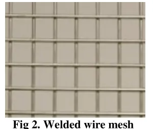
Welded wire mesh: Produced using
longitudinal and transverse wires welded together at the intersections, as illustrated in Fig 5.2. It has a higher stiffness than woven mesh, which is why the welded mesh leads to smaller deflections in the elastic stage. Welded mesh is also more durable, more intrinsically resistant to corrosion and more stable in structures than woven mesh.
Fig 2. Welded wire mesh
Hexagonal or chicken wire mesh: This
mesh is a type of fencing mesh that has
hexagonal holes. It has many different
ISSN : 2581-7175 ©IJSRED: All Rights are Reserved Page 287 Fig 3. Hexagonal or chicken wire mes
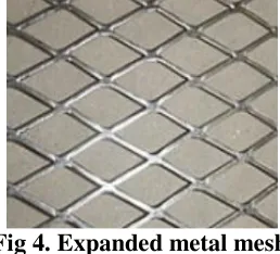
Expanded metal mesh: This is formed
by slitting thin-gauge steel sheets and expanding them perpendicularly to the slits as shown in Figure 2-3d. This type of mesh offers approximately equal strength in the normal orientation but is much weaker in the direction in which the expansion took place. It can be used as an alternative to welded mesh, but it is difficult to use in construction involving sharp curves.
Fig 4. Expanded metal mesh
2. CONSTITUENT MATERIAL 2.1 CEMENT:
Ordinary Portland cement of 43 grade confirming to IS 8112:1989 of locally available RAMCO cement which comprises good quality. The physical and chemical properties are tabulate below.
Description Composition
Physical Properties
Colour Grey
Specific gravity 3.15
Specific surface area
(cm2/g)
3540
Chemical Composition
CaO (%) 62.8
SiO2 (%) 20.3
Al2O3 (%) 5.4
Fe2O3 (%) 3.9
MgO (%) 2.7
Na2O (%) 0.14
K2O (%) 62.8
Table 1: Physical and chemical composition of ordinary Portland cement (OPC)
2.2 FINE AGGREGATE:
For fine aggregates, uncrushed locally available natural river sand is used, and the properties are tested and tabulated below.
Description Composition
maximum size 2.36 mm
fineness modulus 3.35
specific gravity 2.65
Table 2: properties of fine aggregate.
2.3 COARSE AGGREGATE:
For coarse aggregates, locally available natural coarse aggregates is used, and the properties are tested and tabulated below.
Description Composition
maximum size 20mm
specific gravity 2.75
Abrasion value
24.40
Crushing value 21.46
Water absorption 0.97%
Impact value 17.18
Table 3: properties of coarse aggregate
2.4 WATER:
Ordinary potable tap water was tasted and used for mixing and curing.
2.5 ADMIXTURE
ISSN : 2581-7175 ©IJSRED: All Rights are Reserved Page 288
vessels) and to repair or strengthen old structures. In addition, applications of Ferro cement were used for boats, water tanks, shell structure, roof, retrofitting balcony and extension room. Six applications are Recently, many structures have been built using Ferro cement.
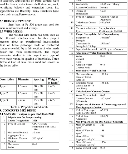
2.6 REINFORCEMENT:
Steel bars of Fe 500 grade was used for main reinforcement and stirrups.
2.7 WIRE MESH:
The welded wire mesh has been used as the flexural reinforcement. In this project presents about an experimental investigation done on beam prototype made of reinforced concrete overlaid by a thin section of wire mesh below the main reinforcement. The major parameter studied in this project were type of wire mesh varied in spacing of interlocks. Three different kind of wire mesh used and shown in the below table.
Description Diameter Spacing Weight
in kg/m2
Type 1 1.5 mm 30 x 30
mm
2.465
Type 2 1.5 mm 25 x 38
mm
2.485
Type 3 2 mm 25 x 38
mm
2.665
Table 4: Properties wired mesh
3. CONCRETE MIX DESIG
3.1M-25 Mix Designs as per IS-10262-2009
I Stipulations for Proportioning
1 Grade Designation M25
2 Type of Cement OPC 43 grade confirming to IS-8112-1989
3 Maximum Nominal Aggregate Size
20 mm
4 Minimum Cement Content
310 kg/m3
5 Maximum Water
0.45
Cement Ratio
6 Workability 50-75 mm (Slump) 7 Exposure Condition Normal
8 Degree of Supervision
Good
9 Type of Aggregate Crushed Angular Aggregate 10 10 Maximum Cement
Content
540 kg/m3
11 Chemical Admixture Type
Superplasticiser Confirming to IS-9103
III Target Strength for Mix Proportioning
1 Target Mean Strength
36N/mm2
2 Characteristic Strength @ 28 days
25N/mm2
3 Superplasticiser used 0.5 % by wt. of cement
IV Selection of Water Cement Ratio
1 Water Cement Ratio
0.45
2 Adopted Water Cement Ratio
0.43
V Selection of Water Content
1 Maximum Water content (10262-table- 2)
186 Lit.
2 Estimated Water content for 50-75 mm Slump
138 Lit.
VI Calculation of Cement Content
1 Water Cement Ratio 0.43 2 Cement Content
(138/0.43)
320 kg/m3
VII Proportion of Volume of Coarse Aggregate &
Fine Aggregate Content
1 Vol. of C.A. as per table 3 of IS 10262
62.00%
2 Vol. of Fine Aggregate
38.00%
VIII Mix Proportions for One Cum of Concrete
1 Mass of Cement in kg/m3
320
2 Mass of Water in kg/m3
138
3 Mass of Fine Aggregate in kg/m3
751
4 Mass of Coarse Aggregate in kg/m3
1356
ISSN : 2581-7175 ©IJSRED: All Rights are Reserved Page 289
Table 5: mix design and mix calculation
3.2 CASTING AND TESTING OF CUBES AND CYLINDERS:
Before casting of beam prototype three number of 150 mm cube specimens and three numbers of 150 mm diameter and 300 mm height cylinder specimens were cast as per IS 516:1959 for finding the compressive strength and tensile strength of concrete. The compressive strength and the split tensile strength was found out at 7 and 28 days of curing. The average compressive strength and tensile strength of M25 grade concrete is shown in Table
Description Compressive
strength (MPa)
Split tensile strength (MPa)
days 7days 28days 7days 28days
strength 19.87 32.7 2.15 3.21
Table 6: compressive strength and split tensile strength.
3.3 BEAM PROTOTYPES
Totally 4 prototype beams were designed for the optimum compressive strength obtained from the mix. The longitudinal bars were of 8 mm diameter and the stirrups were of 6 mm diameter with spacing of 150 mm throughout. The specimen ID for beams are given in Table 6 along with the type of reinforcements used and fig1 shown beam prototypes.
Fig 5. Beam Prototypes
Specimen ID Details
B-1 Control beam RC beam without shear
reinforcement
B-2 RC beam with Type 1
wire mesh
B-3 RC beam with Type 2
wire mesh
B-4 RC beam with Type 3
wire mesh Table 7: Beam Prototype
3.4 TEST SETUP:
The test setup includes two point loading using a single point loading system by which the loads are transferred equally to the two points using a spreader beam and two rollers. Dial gauges are placed in the bottom of the beam at the mid-point to find the deflection. Demes are placed on the surface of the beam to find the surface strains which are placed at a distance of 100mm from one another. The clear setup of the test is shown in the fig.2.The strains at these
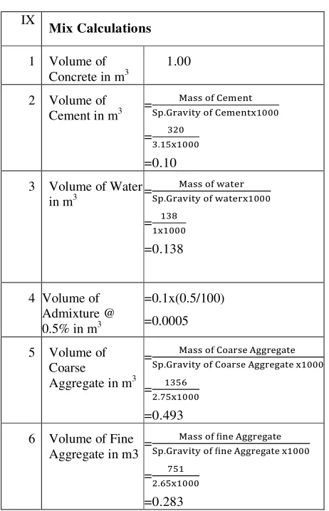
IX
Mix Calculations
1 Volume of Concrete in m3
1.00
2 Volume of
Cement in m3 = .
=
.
=0.10 3 Volume of Water
in m3 = .
= =0.138
4 Volume of Admixture @ 0.5% in m3
=0.1x(0.5/100) =0.0005
5 Volume of Coarse Aggregate in m3
=
.
=
.
=0.493 6 Volume of Fine
Aggregate in m3 =
.
=
.
ISSN : 2581-7175 ©IJSRED: All Rights are Reserved Page 290
points are found using a mechanical strain gauge. The crack patterns are noted on both sides of the beams at particular intervals. The gauge length between the load points is 300 mm and 150 mm are left on both sides of the beam at the supports. All the specimens were capped for uniform loading prior testing. The control of load over the test was 10 kN/min. Automatic data acquisition system was used to record the load, strain and axial displacement which in turn connected to the computer.
Fig 6. Test Setup
4. EXPERIMENTAL RESULTS AND
DISCUSSIONS
4.1 FIRST CRACK AND PEAK LOAD
The beam specimen B-1 the peak load is observed at 30 kN and failed at the peak load of 80.75 kN in shear. The peak load of the control specimen can be taken as maximum permissible shear load. The specimen B-2, B-3and B-4have shown similar load behaviour. The specimen B-2 have shown maximum load capacity of 94.34 kN and failed in flexure. The specimen starts cracking at a load of 30 kN. Whereas the specimen B-3with combination of stirrups and welded wire mesh had a cracking load of 40 kN and a maximum peak load of 110.35 kN. The specimen B-4 had failed at the maximum load of 101.3kN and the first cracks were observed at a load of 35 kN. The cracking load and peak load
of various specimens is given in the Fig.3 below.
Specimen Initial
load(kN)
Maximum Peak Load(kN)
B-1 Control beam
30 80.75
B-2 30 94.34
B-3 40 110.35
B-4 35 101.3
Table 8:Initial loan and maximum peak load
Table 7:Initial loan and maximum peak load
4.2 CRACK PATTERN AND SPACING
All the beam specimens performed well in both shear and flexure. The control specimen provided with only flexure reinforcement failed with a large shear crack having width more than 1mm. For the beam specimen B-2, the beam failed in flexure with equal number of flexure cracks and shear cracks. Specimen B-3performed similar to that of specimen B-2 having lesser number of shear crack than flexural crack. The specimen B-4performed better than other specimens with the cracks distributed all over the surface with the crack width less than 0.1 mm. The crack number shown in table9 and crack pattern of the specimens were given in the Fig.8, to Fig.11 and the Fig.8 for the beam prototype of C, B-2, B-3and B-4respectively.
Specimen Shear zone Flexure zone
B-1 Control beam
6 4
B-2 6 6
B-3 5 6
B-4 5 7
0 20 40 60 80 100 120
B-1 B-2 B-3 B-4
Initial load(kN)
ISSN : 2581-7175 ©IJSRED: All Rights are Reserved Page 291
Table 9:Shear zone and flexural zone
Fig.8 Crack pattern of control beam B-1
Fig.9. Crack pattern B-2
Fig 10. Crack pattern B-3
Fig 11. Crack pattern B-4
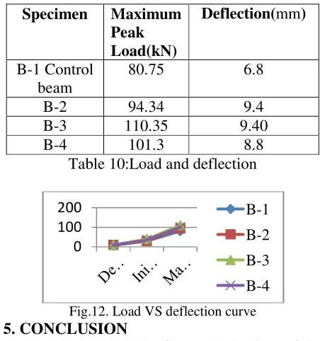
4.3 LOAD DEFLECTION BEHAVIOUR
Fig.12 shows the load-deflection curves for beams tested. In general, beams with wire mesh layer exhibited greater stiffness than the control specimens. The ratio of the average total deflection near ultimate load for specimens with wire mesh to the corresponding average value of the control specimens was 0.87, 0.74 and 0.73 specimen B-2, specimen B-3and specimen B-4, respectively. The reduction in the deflection was higher for specimens B-2. The control beam failed at the peak load of 80.75 kN in shear with deflection of 9.4mm. The specimen B-2, B-3and
B-4have shown similar load-deflection
behaviour. The specimen B-2 with have shown maximum load capacity of 94.85 kN and failed in flexure with deflection of 6.8mm. Whereas the specimen B-3with combination of stirrups and welded wire mesh underwent more load-deflection behaviour with load-deflection of 9.40mm at 110.4 kN. The specimen B-4had failed at the maximum load of 101.45kN with far less
deflection of 8.8mm.
Specimen Maximum
Peak Load(kN)
Deflection(mm)
B-1 Control beam
80.75 6.8
B-2 94.34 9.4
B-3 110.35 9.40
B-4 101.3 8.8
Table 10:Load and deflection
Fig.12. Load VS deflection curve
5. CONCLUSION
The study on the flexural behaviour of the beam specimens, with wire mesh encased the steel reinforcement have led to the following conclusions.
Wire mesh when used as an additional reinforcement in beam, enhanced the flexural behaviour of the beam by distributing the forces along the section.
It can be observed that, the first crack and ultimate strength increases up to 30% and 37% respectively with the use of wire mesh.
Compared to the control beam, the peak load increased by 17%, 26% and 37% for beam B-2, B-3and B-4respectively. This shows that the beam has significant effect on spacing and diameter of the rod. Rectangular wire mesh performed better than square type wire mesh.
The use of wire mesh have made a significant effect on crack pattern of the reinforced concrete beams by delaying the crack appearance, increasing the number of crack and reducing the crack width.
The ultimate moment capacity for the beam specimens have considerably improved with the use of wire mesh.
0 100
200 B-1
B-2
B-3
ISSN : 2581-7175 ©IJSRED: All Rights are Reserved Page 292
Compared to the control beam specimen,
the energy absorption capacity improved
significantly for wired mesh RC-beam. Energy absorption capacity is more for wire mesh having greater diameter rod about 30% greater than control beam.
REFEREBashandy, “Experiments on flexural
strengthening of reinforced concrete beams using
valid strengNCES
[1] AlaaA. thening techniques”, ActaTechnica Napocesis: civil Engineering and Architecture, Vol.56, No.1, Pp.36-50, 2013.
[2] Damyanti G Badagha and C.D.Modhera, “Studies on harden properties of mortar using
polyester fibre”, International Journal of
Advances in Engineering and Technology, Vol.6, No.3, Pp.1154-1159, 2013.
[3] H.A.Ezz-Eldeen,“An experimental study on strengthening and retrofitting of damaged reinforced concrete beams using steel wire mesh and steel angles”, International Journal of Engineering Research and Technology , Vol.4, No. 5, Pp.164-173,2015.
[4] L.Ganapathy and N.Sakthieswaran,
“Strengthening of reinforced cement concrete beam using fibrous ferrocement laminates", International Journal of Science and Engineering Research, vol.3, No.5,Pp. , 2015.
[5] S.U.Khan, M.F.Nuruddin, T.Ayub and
N.Shafiq, “Effects of ferrocement in
strengthening the serviceability properties of
Reinforced concrete structures", Advanced
Material Research,Vol.690,Pp.686-690,2013.
[6] S.U.Khan,S.F.A.Rafeeqi and T.Ayub,
“Strengthening of RC beam in flexure using ferrocement”, IJST, Transactions of Civil Engineering, Vol. 37, No. C+, Pp 353-365, 2013.
[7] R.Malathy, J.Sridhar and
R.K.Sangeetha,“Flexural strengthening of
reinforced concrete beams using ferrocement laminates with partial replacement of fine aggregate by steel slag”, Journal of Engineering and Technology, Vol.4, No.2, Pp.123-126,2014.
[8] Md.MotiurRahman,TahminaTasnimNahar
and Anish kumersaha, “Effect of wire mesh on the strength of R.C.C beams repaired using ferrocement layers”, International Journal for Research and Development in Technology ,Vol.1,No.1,Pp.13- 18,2014.
[9] A.E.Naaman and Victor C.Li, “Bending response of hybrid ferrocement plates with meshes and fibers”, Journal of Ferrocement, vol.34, No.1, pp.275-288, 2004.
[10] D.Rajkumar and B.Vidivelli, “Acrylic rubber latex in ferrocement for strengthening reinforced concrete beams", American Journal of Engineering and Applied sciences, Vol.3.No.2, Pp.277-285, 2010.
[11] IS 8112:2013, Indian standard ordinary Portland cement, 43 grade – specification, Bureau of Indian Standard, ManakBhavan, 9 Bahadur Shah Zafar Marg, New Delhi 110002.
[12] IS 10262- 2009, Indian Standard for Concrete Mix Proportioning – Guidelines, Bureau of Indian Standard, ManakBhavan, 9 Bahadur Shah Zafar Marg, New Delhi
110002.
[13] IS 456 – 2000, Indian Standard PLAIN AND REINFORCED CONCRETE - CODE OF
PRACTICE, Bureau of Indian Standard,
ManakBhavan, 9 Bahadur Shah Zafar Marg, New Delhi 110002.
[14] IS 9103:1999, Specification for Concrete
ISSN : 2581-7175 ©IJSRED: All Rights are Reserved Page 293
ManakBhavan, 9 Bahadur Shah Zafar Marg, New Delhi 110002.
[15] IS 2386 (Part III) – 1963, Indian Standard Methods of Test for aggregates for Concrete Part III Specific gravity, Density, Voids, Absorption and Bulking, Bureau of Indian Standard, ManakBhavan, 9 Bahadur Shah Zafar Marg, New Delhi 110002.
[16] IS 516 – 1959, Indian Standard Methods of Tests for Strength of Concrete, Bureau of Indian Standard, ManakBhavan, 9 Bahadur Shah Zafar Marg, New Delhi 110002.