Tribology in Industry
www.tribology.rsStudies on Plasma Sprayed Thermal Barrier Coating
with Increase in Coating Thickness
H. Nayak
a, N. Krishnamurthy
b,
R.A. Shailesh
caDepartment of Mechanical Engineering, PESIT, Bangalore South Campus, Bengaluru-560100, India,
b Department of Mechanical Engineering, Vijaya Vittala Institute of Technology, Dodda Gubbi, Bengaluru-560077, India, cDepartment of Mechanical Engineering, K.S.School of Engineering and Management, Bengaluru-560062, India.
Keywords:
Plasma spray
Thermal barrier coating Microstructure
Wear
Bond strength Hot corrosion
A B S T R A C T
In this study, the nature of performance test like a bond test, wear test and hot corrosion test and its effects on plasma sprayed Yttria-stabilized zirconia and Al2O3 composite (50:50 compositions) coating
on Aluminium 6061 substrate are carried out. The three topcoat thicknesses of 100µm, 200µm, and 300µm are used for the studies. In case of hot corrosion test, the substrates were spread by molten salt (55wt.% V2O5+45wt.%Na2SO4) which is kept in the furnace at 350 °C
for 40 hours. The properties changed for the different bond thickness where for 200 µm wear properties become optimal and 300 µm the corrosion test remains optimal. There is an improvement in the bond strength and its optimal value is obtained for 100 µm topcoat thickness. The physics behind all three experiments are explained in this paper.
© 2018 Published by Faculty of Engineering Corresponding author:
Haridasa Nayak
Department of Mechanical Engineering, PESIT, Bangalore South Campus, Bengaluru-560100 India.
E-mail: [email protected]
1. INTRODUCTION
The Internal Combustion Engines (IC Engines) are of several types, which are used for automobile, marine and power generation and the purpose of this engine is to develop high power, effectively use the fuel, it's multi-fuel capacity and much more. Recently there are lots of innovations that are happening to improve the engine efficiency. It is to be noted that the piston during its movement inside the cylinder liner develops huge thermal properties which result in wear and corrosion at the inner circumference of the liner. This coating is most expedient and spraying technique, where the coating materials hit the liner surface with high velocity and make bonding with the substrate.
To improve the effective use of the liner, a thin layer of coating is spread inside the circumference and multiple discussions are recently seen in these directions. Generally, there are lots of works that are carried out in understanding the coating performance relate to its strength, wear and corrosion.
There are some researchers investigated in predicting the bond strength of the coating materials with the substrate. C.K. Abdulla [1] investigated the strength of the interface between the coating and substrate region. He mentioned that the adhesion strength increases with the different coating temperatures and coating techniques. Some studies on bending test to study the strength on the
coating-R
ES
EA
R
substrate junction are seen [2,3]. The result obtained was primary in nature and directed some methods in finding the bond strength of the coating. D J Greving [4] studied the bond strength for thermal barrier coating and other top coats and discussed the influence of coating residual stress and coating thickness. There are also studies on thermal spray coating for NiCo CrAlY-coated superalloy substrates through Nanostructured and conventional coating methods [5]. The wear properties for stainless steel or cast iron substrate are studied by various researchers. The ceramic coating of yttrium-stabilized zirconia inside the stainless steel substrate through atmospheric plasma spray coating techniques is studied and mentioned the improvement in the wear properties for lubricated conditions [6,7]. Rajarathnam [8] studied the microstructure and abrasive wear properties of AISI1040 steel surface with Cr2O3 ceramic materials. The microcracking was increased in some cases due to the increase in microhardness value on the coating after the wear. N Krishnamurthy [9] studied alumina and yttria-stabilized zirconia coated using atmospheric plasma spray coating in equal proportion for Al6061 alloys. He noted that the bond loses its strength when the material comes in contact with the disc. There are studies on the sprayed coating techniques for Inconel-718 and discussed the wear properties and erosion [10-12]. The impurities such as sodium sulphur and vanadium formed during combustion react with the Thermal Barrier Coating (TBC) and delaminate from the substrate. S.Y. Park [13] studied the effects of yttria stabilizer replacement on hot corrosion properties of TBC through microstructural techniques. The results revealed that CSZ TBC was better resistance to hot corrosion than YSZ TBC relates to phase stability. It is to be noted that when the as-sprayed and laser glazed TBCs exposed to the hot corrosion dipped in molten salts there is additional stress and degradation of the coatings [14,15]. Some studies also mentioned that the hot corrosion behaviour for plasma spray thermal barrier coating is better than solution precursor plasma spray (SPPS) thermal barrier coating and have longer life cycle [16]. Finally, some discussions on destructive factors for thermal barrier coating are also seen [17-19]. In most of the cases, the thermal barrier coating will be divided into thin and thick coatings. Thin coatings will range from
100-1000 µm (0.1-1 mm) and above 1000 µm were classified as thick coatings. Thin coatings are used in a gas turbine, different parts of I.C.Engines such as piston tops, cylinder heads, cylinder liners and valves [20,21].
Overall from the above, it is understood that a lot of researchers presently are working on improving the coating material to increase the bond strength and minimize the wear and corrosion properties. From the recent publications and literature, most of the work is carried out in selecting a single topcoat material, either Al2O3 or YSZ or calcia stabilized Zirconia or some other materials as top coating and studied its performance during piston functioning. Here the combination of YSZ and Al2O3 are tried to understand its strength in the hot environment. To carry out this test, the top coat thickness of 100µm, 200 µm and 300 µm are spread on the Al6061 substrate are processed. The interface bond coats METCO 410NS and METCO 446 having 75 µm thicknesses are used for bonding the coating with the substrate. The bond test, wear test and hot corrosion studies for these materials are studied and analyzed in detail.
2. EXPERIMENTAL DETAILS
300 µm respectively. Used two bond coat of thickness of 75 µm for each specimen [20,21,23-26]. Atmospheric plasma spraying (APS) technique was adopted in our investigation. The spray parameter considered for the coating is given in Table 1.
Table 1. Plasma Spray processing for Aluminium substrate.
Material TC BC1 BC2
Primary gas Pressure (Argon)
kPa 700 520 700
Secondary gas Pressure (Hydrogen)
kPa 520 340 350
Carrier gas (Argon) flow
lpm 60 37 37
Current
A 600 500 500
Voltage
V 65 70 65
Spray distance
mm 64-125 100-500 75-125
Feed rate
kg/h 2.7 3.2 1.6
Wear rate is calculated on the basis of following formula: Volume of wear=wear lose x (πd2 /4) Wear rate=volume of wear/ (load x sliding distance).
3. RESULT AND DISCUSSION
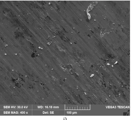
The microstructures of the coating for 100 µm coating thickness are shown in Fig. 1. From the microstructure, it reveals that a large number of molten particles are seen on the surface. It indicates that the proper procedure that has been carried out during the spraying process. A small amount of un-melted particles with powder materials are seen on the surface. This may be due to powder particles on the un-melted surface and forms micro weld. Even some small amounts of pores are also seen on the surface. Similar observations are also seen for 200 µm and 300 µm coating thickness.
3.1Effect of curing on adhesion strength and mechanical properties of TBCs
To measure the adhesion strength of the coating, the tensile tests were carried out on the basis of C-633 ASTM test standard and failures of coating surface were analyzed. The three types of failures such as i) Adhesive ii) cohesive iii)
combination of both cohesive adhesive failure occur and most of the cases cohesive failure occur Fig. 2. From the experiments, the average bond strength of 198.1515MPa is exhibited for thin coating and its average value for the thicker bond strength is 161.9301MPa. For the middle coating thickness, the bond strength of 176.8153 MPa is found. It is clear evidence that the bond strength decreases with increase in thickness of the coatings, above observation, also agreed by the earlier researcher [3,27,28]. Due to the thermal cyclic effect, more residual stresses will build up, which perhaps reduce the top coating strength of the layer. There was 10 % reduction in the bond strength for increasing the thickness from 100 to 200 µm and a further increase in thickness, the bond strength reduces up to 20 %. In case of the lower thickness of the coating, the hot spray hits the substrate and most of the heat is transferred to the substrate and thus forms lower residual stresses in the coating. With the increase in its thickness, the hot spray when hits the coating layer finds difficult to transfer the heat to the substrate and forms higher residual stresses. This, in turn, reduces the bond strength of the coating.
Fig. 1. The microstructure of coating for S1.
a) MELTED
PARTICLES
UNMELTED PARTICLES
b)
c)
Fig. 2. a)Cohesive, b)Adhesive, c)Combination of the adhesive and cohesive mode of failure.
Fig. 3. Bond strength v/s thickness of the coating.
Further, the joined specimens after glueing were cured at 70 °C for two hours and cool down to its room temperature in the furnace and the bond strength for these specimens are also carried out Fig. 3. This method has a profound influence in increasing the bond strength where for 100 µm around 223.747 MPa are formed. For the bond thickness of 200 and 300 µm the strength of 196.0993 MPa, 175.192 MPa are formed respectively. The heating effect between the substrate and coating junction will improve the bonding that matches with the previous investigators [3,5] and also minimizes the residual stresses in the coating material.
3.2Effect of Wear
The wear is the interaction among the mating surfaces where the ploughing and rubbing of
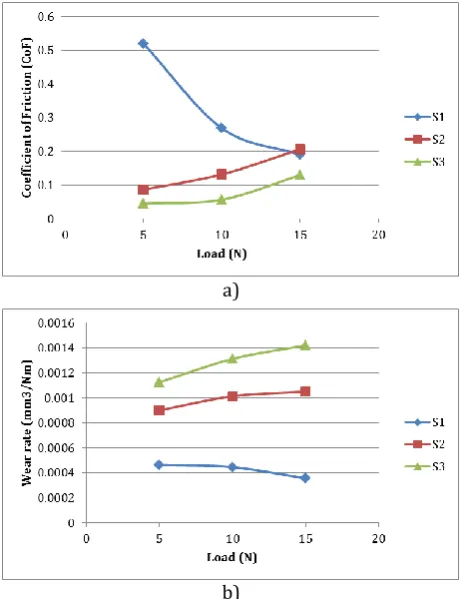
material between the surfaces take place. The coefficient of friction (COF) and wear rate for the different load condition for the three samples are shown in Fig. 4. For a given load condition, for the entire three specimens, there is an initial increase in the COF value for a given load condition. This is due to the cold mating surface (When the specimen and abrasive wheel are at room temperature during the commencement of experiment), which are rubbed, thereby develops some friction initially. The increase in the temperature on the mating surface and especially on top coat material lodges out uneven particles and small dislocation may happen on the coating material. This smooth surface when rub with the abrasive wheel reduces the friction after a certain stage.
a)
b)
Fig. 4. a) Coefficient of friction (COF), b) Wear rate for the different load condition.
From the wear rate, more materials are removed from the top coating due to dynamic imbalances forces on the mating surface. The wear rate increases for S2 and S3 topcoat thickness. In case of S1, wear rate slightly decreases for 15N, which may be due to absorption of thrust force by the substrate. Further, the SEM images of the wear samples for the different loads are shown in Fig. 5. For a better understanding of wear mechanism, the whole parts of the sample were examined under SEM. From the scratch analysis, the S1 top coating has a high intensity of wear for the lower load (5 N) condition. During the wear test, the top coat and bond coat almost got erased out and the surfaces of the substrate are seen from the image. With the increase in the load, the absorption of thrust force form during the motion by the substrate reduces the wear and the top coat and bond coat are visible with an increase in the load condition.
a)
b)
c)
d)
e) Wear tracks
Wear tracks
Wear track
Direction of ploughing
f)
g)
h)
i)
Fig. 5. SEM image of the sample for a) 5N, b) S1-10N, c) S1-15N, d) S2-5N, e) S2-S1-10N, f) S2-15N, g) S3-5N, h) S3-10N, i) S3-15N load condition after wear.
This may not happen for S2 and S3 specimen. With the increase in the coating thickness, there is no much absorption of high thrust force at 15 N load condition and hence the substrates are clearly visible for the S2 and S3 specimens. With the decrease in the load, even some bonding may take place, the coat materials are seen during the SEM analysis.
3.3Effect of Corrosion on coating before and after the hot corrosion test
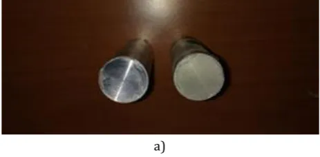
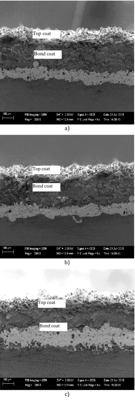
For understanding, the coating layers and substrate before the corrosion test are shown in Fig. 6. The Figure 7 represents the SEM images of the cross-sectional of the top coat after the hot corrosion test. The crack was formed between the top and bond coat for S1 sample and mere crack formation was seen for the other two samples. The crack generated makes a way for sodium sulphate and vanadium pentoxide, which is formed due to pasting of corrosive salts to reach near the bond coat and forms ZrO2in the monoclinic phase. Also, the porosity formed makes these impurities to reach the bond coat and peals the top coat from the substrate. These unstable natures during the process make an easy way for the impurities to reach the bond coat and are easily detached from the substrate. In case of higher coat thickness, the crack and porosity formation reduce, which in turn resist the impurities to reach the bond coat. This result in a reduction in corrosion and it can be easily visible in SEM images of the after-corrosion S3 specimen.
a)
b)
c)
Fig.6. Cross-sectional SEM image of as-sprayed coating systems for specimen: a) S1, b) S2, and c) S3.
a)
b)
c)
Fig. 7. Cross-sectional SEM image of coating for the specimen: a) S1, b) S2, and c) S3 after hot Corrosion test.
Bond coat Top coat
Top coat
Bond coat
Top coat
4. OVERALL DISCUSSION
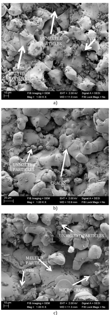
The investigations on improvement in the coatings were carried out on cylindrical liners. The coating adheres firmly to the substrate by the help of bond coat and the functional characteristics vary with the increase in temperature. Overall, the process of coating with the substrate should minimize the misfit between them and reduce porosity. The bond loosens with the increase in temperature and due to the piston moment, all the coating materials come out which indicates a poor coating material. Initially, the coating material should adhere with the substrate and understand this, bond strength is carried out. The repeatability of the test for three samples for each topcoat thickness variant was performed and verified. A reasonable increase in the bond strength is achieved with the decrease in the coating thickness. In case of lower coat thickness; the tensile stress was within the adhesion strength of TBC. From the top surface morphology, a strong bond was noticed with a mere amount of coat material stick in the uncoated surface and the tensile strength of 223.747 MPa was achieved during the process. With the increase in coating thickness, layer by layer adhesion of coating material results in an uneven bonding between them due to thermal differences. This leads to increasing the residual stress and decrease the strength of the top coat. In case of 200 and 300 µm top coating thickness, the residual stress gradually increases and in turn bond strength reduces. A mixed failure mechanism (Adhesion and Cohesion) with a decrease in the cohesive strength with increase in coating thickness were observed (Fig. 2c). Also, the morphology of the coated samples S1, S2 and S3 are illustrated in the Fig. 8. From the observation, for S1 samples, the top coat consisting of melt and semi-melt particles, splats and un-melt particles are seen. Some voids and microcracks are also observed in these coating materials. The existences of microcracks are mainly due to the formation of residual stresses introduced during the spraying process [14]. With the increase in coating thickness (S2 and S3 samples), the formation of voids and un-melt materials are gradually reduced. This understands the reduction of residual stresses during the processes.
MELTED PARTICLES
UNMELTED PARTICLES
VOIDS
a)
CRACKS UNMELTED
PARTICLES
b)
MELTED PARTICLES
UNMELTED PARTICLES
MICROCRACKS
VOIDS
c)
a)
b)
c)
d)
e)
f)
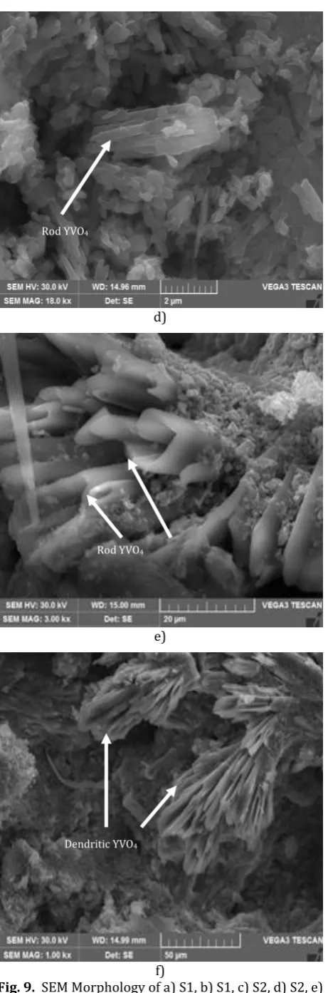
Fig. 9. SEM Morphology of a) S1, b) S1, c) S2, d) S2, e) S3, and f) S3 coated samples after hot corrosion test.
Rod YVO4
ZrO2 +Al2O3
Dendritic YVO4 YVO4
YVO4
RodYVO4 ZrO2 +Al2O3
The wear graph of coating material for the different load condition reveals an increase in the COF value for the lower coating thickness. The nature of the abrasion between the asperities of the coating material and disc increases for the lower load of 5N. The surface then gets exposed to the bond coat and substrate and large area of the substrate is clearly visible in the image. With the increase in the load to 15 N, there is not much peeling of the bond coat as noticed from the SEM image. The transformations of Al2O3 coating to α-Al2O3 may resist the wear loss during the process [9]. With the increase in the coating thickness, there is a poor bonding between the successive layers of coating for lower loading conditions that lead to the delamination of the coating. This results in the rapid wear of the ceramic coating. Here the wear takes place by ploughing mechanism, where the ploughing lips are clearly visible for the lower load at 5 N, with the increase in the load, the more friction generated forms α-Al2O3 on the surface and resists the wear. A similar phenomenon was observed by the earlier researcher also [31]. The severe deformation did not happen for this case and the top coat and bond coat are visible in the images.
C
ou
nt
s
Energy (in keV)
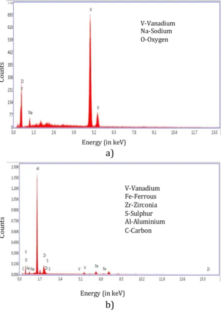
V-Vanadium Na-Sodium O-Oxygen a) C ou nt s
Energy (in keV)
V-Vanadium Fe-Ferrous Zr-Zirconia S-Sulphur Al-Aluminium C-Carbon b)
Fig. 10. a)EDS pattern of coating on the top surface of the coating after hot corrosion,b)EDS pattern of coating on the cross-section of the coating after hot corrosion.
20 30 40 50 60 70 80 90 100
0 800 1600 2400 3200 4000 4800 5600 6400 7200 8000 8800 9600 Inten sity ( co u n ts/s ec)
2 (degree)
S3 S2 S1
ZrO2(tetragonal)
Al2O3(cubic) Al2O3(orthorhombic)
Al
2O3(corundum)
S1 S2 S3
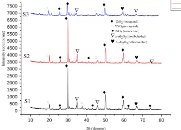
10 20 30 40 50 60 70 80 0 500 1000 1500 2000 2500 3000 3500 4000 4500 5000 5500 6000 6500 7000 7500
2(degree)
S3 S2 S1 S1 S2 S3
ZrO2 (tetragonal)
Inten sity ( co u n ts/s ec)
YVO4(tetragonal)
ZrO2 (monoclinic)
-Al2O3(rhombohedral)
Al2O3(orthorhombic)Fig. 12. XRD patterns coated samples after hot corrosion test.
The coating morphology after the corrosion tests is shown in Fig. 9. In the top coat, for all the samples, the different shapes of the V2O5 rod and dendritic structure are seen. These formations of shapes are more for the samples S1 and S2. Also, from the XRD analysis, for the samples before the corrosion test, the coating systems consisting of ZrO2 (Tetragonal) and Al2O3 (Cubic) crystalline polymorphic phase are seen Fig. 11. But after the corrosion tests, the formation of YVO4 in rod and dendritic form are seen. This is due to the presence of oxygen, sodium and sulphur present in the coating system. Further, the formation of monoclinic ZrO2 and YVO4 crystals were seen on the surface of the coatings sample after introduction to molten salts at 350°. This phase then changes to the tetragonal zirconia phase with rising in the temperature for 320-340 °C. This tetragonal phase will exchange back to monoclinic zirconia phase amid cooling and this will proceed for remaining cycles lastly it will prompt spallation of the coating from the substrate. Further, with the increase in the coating thickness, the formations of YVO4 are reduced in the top coat. From the XRD patterns Fig. 12, the corrosive products such as monoclinic YVO4 and ZrO2 are less visible and have less intensity of peak higher coating thickness. It is clear evidence that an increase in the coating thickness of Al2O3 and YSZ, the more
resistance towards the corrosion are seen. The thickness of the coating will resist the penetration of corrosive salts from the top coat to the bottom coat.
5. CONCLUSIONS
The Aluminium 6061 substrate was coated with the equal proportions of YSZ and Al2O3 materials for the three thickness values and bond strength, wear characterization and corrosion properties were studied. The following points can be concluded from the above:
The obtained Bond strength for the thin coating (S1) with heat treated and without heat treated are 223.747MPa and 198.1515MPa respectively. For thick bond coating (S2 and S3), the strength of
196.0993MPa, 175.192MPa and
176.8153MPa, 161.9301MPa respectively are formed for both treatments.
The wear resistance is large for the lower loading condition and coat thickness. With the increase in the coating thickness, the wear increases with the increasing load condition due to the increase in the formation of the residual stress.
The corrosion of the lower coat thickness increases and further with the increase in the coating thickness the corrosion properties decreases.
REFERENCES
[1] C.A. Karaoglanli, H. Dikici, Y. Kucuk, Effects of heat treatment on adhesion strength of thermal barrier coating systems, Engineering Failure Analysis 32, vol. 32, pp. 16-22, 2013, doi: 10.1016/j.engfailanal.2013.02.029
[2] H. Cohrt, F. Thummler, Degradation Mechanisms Of Thermal Barrier Coatings In Bending Tests, Surface and Coatings Technology, vol. 32, iss. 1-4, pp. 339-348, 1987, doi: 10.1016/0257-8972(87)90118-6
[3] M. Okazaki, S. Yamagishi, Y. Yamazaki, K. Ogawa, H. Waki, M. Arai, Adhesion strength of ceramic top coat in thermal barrier coatings subjected to thermal cycles: Effects of thermal cycle testing method and environment,
International Journal of Fatigue, vol. 53, pp. 33-39, 2013, doi: 10.1016/j.ijfatigue.2012.02.014
[4] D.J. Greving, J.R. Shadle, E.F. Rybicki, Effects of Coating Thickness and Residual Stresses on the Bond Strength of ASTM C633-79 Thermal Spray Coating Test Specimens, Journal of Thermal Spray Technology, vol. 3, pp. 371-378, 1994,
doi: 10.1007/BF02658982
[5] H. Jamali, R. Mozafarinia, R.S. Razavi, R. Ahmadi-Pidani, Mohammad Reza Loghman-Estarki,
Fabrication and Evaluation of Plasma-Sprayed Nanostructured and conventional YSZ Thermal Barrier Coatings, Current Nanoscience, vol. 8, no. 3, pp. 402-409, 2012.
[6] K. Brinkiene, R. Kezelis, Juratecesniene, V. Mecius, Evaluation of Wear Resistance of Plasma Sprayed Ceramic Coatings, Materials Science (Medziagotyra), vol. 15, no. 4, pp. 302-305, 2009. [7] K. Brinkiene, R. Kezelis, J. Cesniene, V. Mecius, A. Zunda, Characterization of Wear Properties of Plasma Sprayed Ceramic Coatings, Materials Science (Medziagotyra), vol. 14, no. 4, pp. 345-349, 2008.
[8] D.R.P. Rajarathnam, M. Jayaraman, K.K. Ramasamy, M. Premkumar, D.S. Narayana, An Experimental Investigation on Abrasive Wear
Behaviour of Different Ceramics Coating on AISI 1040 Steel by Plasma Process, Middle-East Journal of Scientific Research, vol. 23, no. 6, pp. 1237-1242, 2015.
[9] N. Krishnamurthy, M.S. Prashanth Reddy, H.P. Raju, H.S. Manohar, A Study of Parameters Affecting Wear Resistance of Alumina and Yttria-Stabilized Zirconia Composite Coatings on Al-6061 Substrate, International Scholarly Research Network ISRN Ceramics, vol. 2012, pp. 1-13, 2012, doi:10.5402/2012/585892
[10]C.S. Ramesh, S. Kumar, D.S. Devaraj, R. Keshavamurthy, Slurry Erosive Wear Behaviour of Plasma Sprayed Inconel-718 Coatings on Al6061 Alloy, Journal of Minerals & Materials Characterization & Engineering, vol. 10, no. 5, pp. 445-453, 2011, doi: 10.4236/jmmce.2011.105033
[11]A. Afrasiabi, A. Kobayashi, Hot corrosion control in plasma sprayed YSZ coating by alumina layer with evaluation of the microstructure and Nanoindentation data (H, E), Vacuum, vol. 88, pp. 103-107, 2013, doi:10.1016/j.vacuum.2012.03.024
[12]X. Zhou, Z. Xu, L. Hec, J. Xu, B. Zou, X. Cao, Hot corrosion behaviour of LaTi2Al9O19 ceramic exposed to vanadium oxide at temperatures of 700-950◦C in air, Corrosion Science, vol. 104, pp. 310-318, 2016, doi: 10.1016/j.corsci.2015.12.024
[13]S.Y. Park, J.H. Kim, M.C. Kim, H.S. Song, C.G. Park,
Microscopic observation of degradation behaviour in yttria and ceria stabilized zirconia thermal barrier coatings under hot corrosion, Surface & Coatings Technology, vol. 190, iss. 2-3, pp. 357– 365, 2005, doi: 10.1016/j.surfcoat.2004.04.065
[14]C. Batista, A. Portinha, R.M. Ribeiro, V. Teixeira, C.R. Oliveira, Evaluation Of Laser-Glazed Plasma-Sprayed Thermal Barrier Coatings Under High-Temperature Exposure To Molten Salts, Surface and Coatings Technology, vol. 200, iss. 24, pp. 6783-6791, 2006, doi: 10.1016/j.surfcoat.2005.10.011
[15]M. Daroonparvar, M.A.M. Yajid, M.Y. Noordin, M.S. Hussain, The Role of Nanostructured Al2O3 Layer in
Reduction of Hot Corrosion Products in Normal YSZ Layer, Journal of Nanomaterials, vol. 2013, pp. 1-13, 201-13, doi: 10.1155/2013/251921
[16]A. Ajay, V.S. Raja, G. Sivakumarb, S.V. Joshi, Hot corrosion behaviour of solution precursor and atmospheric plasma sprayed thermal barrier coatings, Corrosion Science, vol. 98, pp. 271-279, 2015, doi: 10.1016/j.corsci.2015.05.034
[18] M. Makesh, P. Palanisamy, K. Devakumaran, High-Temperature Oxidation And Hot Corrosion Behaviour Of Plasma Sprayed YSZ Coating On Sa213 T92 Steel In Air And Salt At 900°C Under Cyclic Condition, ARPN Journal of Engineering and Applied Sciences, vol. 10, no. 1, pp. 235-241, 2015. [19]D. Gond, D. Puri, S. Prakash, Hot Corrosion
Behaviour of Yttria-Stabilised Zirconia as Plasma Sprayed Coated Boiler Steel in Air and Salt at 900°C under Cyclic Condition, Journal of Minerals & Materials Characterization & Engineering, vol. 10, no. 5, pp. 463-478, 2011,
doi: 10.4236/jmmce.2011.105035
[20] M. Ciniviz, M.S. Salman, E. Canlı, H. Köse, Ö. Solmaz,
Ceramic Coating Applications and Research Fields for Internal Combustion Engines, in F. Shi, Ceramic Coatings, INTECH Open Access Publisher, pp.195-234, 2012, doi: 10.5772/29993
[21] A. Lepeshkin, Investigations of Thermal Barrier Coatings for Turbine Parts, in F. Shi, Ceramic Coatings, INTECH Open Access Publisher, pp. 129-166, 2012, doi: 10.5772/31354
[22]Y.-S. Oh, S.-W. Kim, S.-M. Lee, H.-T. Kim, M.-S. Kim, H.-S. Moon, Effect of the Raw Material and Coating Process Conditions on the Densification of 8 wt% Y2O3-ZrO2 Thermal Barrier Coating by
Atmospheric Plasma Spray, Journal of the Korean Ceramic Society, vol. 53, no. 6, pp. 628-634, 2016, doi: 10.4191/kcers.2016.53.6.628
[23] S.-H. Jung, S.-H. Jeon, J.-H. Lee, Y.-G. Jung, I.-S. Kim, B.-G. Choi, Effects of Composition, Structure Design and Coating Thickness of Thermal Barrier Coatings on Thermal Barrier Performance, Journal of the Korean Ceramic Society, vol. 53, no. 6, pp. 689-699, 2016, doi: 10.4191/kcers.2016.53.6.689
[24]R. Ragupathy, R.K. Mishra, R.D. Misal, Life Estimation of TBC on an Aero Gas Turbine Combustor: A Finite Element Approach, in ASME 2011 Turbo Expo: Turbine Technical Conference and Exposition, 6-10 June, 2011, Vancouver, British Columbia, Canada, pp. 1-7,
doi: 10.1115/GT2011-45027
[25]L. Wang, X.H. Zhong, Y.X. Zhao, S.Y. Tao, W. Zhang, Y. Wang, X.G. Sun, Design and optimization of coating structure for the thermal barrier coatings fabricated by atmospheric plasma spraying via finite element method, Journal of Asian Ceramic Societies, vol. 2, iss. 2, pp. 102-116, 2014, doi: 10.1016/j.jascer.2014.01.006
[26]D. Das, G. Majumdar, R.S. Sen, B.B. Ghosh, The Effects of Thermal Barrier Coatings on Diesel Engine Performance and Emission, Journal of the Institution of Engineers (India): Series C, vol. 95, iss. 1, pp. 63-68, 2014, doi: 10.1007/s40032-014-0104-6
[27]R.A. Mahesh, R. Jayaganthan, S. Prakash,
Microstructural Characteristics and Mechanical Properties of HVOF sprayed Nicral coating on superalloys, Journal of Alloys and Compounds, vol. 468, iss. 1-2, pp. 392-405, 2009, doi: 10.1016/j.jallcom.2008.01.025
[28]N. Krishnamurthy, M.S. Murali, B. Venkataraman,
P.G. Mukunda, Erosion behaviour of plasma sprayed Alumina and Calcia Stabilized zirconia coatings on Cast iron Substrate, in F. Shi, Ceramic Coatings, INTECH Open Access Publisher, pp. 99-126, 2012, doi: 10.5772/30912
[29]X. Tang, V. Prakash, J. Lewandowski, Dynamic Tensile Deformation of Aluminium Alloy 6061-T6 and 6061-OA,
https://www.researchgate.net/publication/229 004194
[30]Sulzer Metco, Thermal Spray Materials Guide, March 2012.
[31]D. Kumar, K.N. Pandey, Study on dry sliding wear