http://dx.doi.org/10.4236/cn.2013.53B2024 Published Online September 2013 (http://www.scirp.org/journal/cn)
Partial Feedback Based Orthogonal Space-Time Block
Coding With Flexible Feedback Bits
*
Lei Wang, Zhigang Chen
School of Electronics and Information Engineering, Xi’an Jiaotong University, Xi’an, China Email: [email protected], [email protected]
Received June, 2013
ABSTRACT
The conventional orthogonal space-time block code (OSTBC) with limited feedback has fixed feedback bits for
the specific transmit antennas. A new partial feedback based OSTBC which provides flexible feedback bits is
proposed in this paper. The proposed scheme inherits the properties of having a simple decoder and the full diversity of
OSTBC, moreover, preserves full data rate. Simulation results show that for transmit antennas, the proposed
scheme has the similar performance with the conventional one by using
1
p
T
n p
T
n p
1
p feedback bits, whereas has the better
performance with more feedback bits.
Keywords: MIMO; Transmit Diversity; Space-time Block Coding; Partial Feedback
1. Introduction
Orthogonal space-time block coding (OSTBC) is a sim- ple and effective transmission paradigm for MIMO sys- tem, due to achieving full diversity with low complexity [1]. One of the most effective OSTBC schemes is the Alamouti code [2] for two transmit antennas, which has been adopted as the open-loop transmit diversity scheme by current 3GPP standards. However, the Alamouti code is the only rate-one OSTBC scheme [3]. With higher number of transmit antennas, the OSTBC for complex constellations will suffer the rate loss.
Focusing on this drawback, the open-loop solutions have been presented, such as the quasi-OSTBC (QOS- TBC) [4] with rate one for four transmit antennas, and other STBC schemes [5,6] with full rate and full diver-sity. Alternatively, the close-loop solutions have also been designed to improve the performance of OSTBC by exploiting limited channel information feedback at the transmitter. In this paper, we focus on the close-loop scheme.
Based the group-coherent code, the bits
feed-back based OSTBC for T transmit antennas has been
constructed in [7], and generalized to an arbitrary number of receive antennas in [8]. The partial feedback based
schemes in [7,8] exhibit a higher diversity order while preserving low decoding complexity. However, these
schemes for transmit antennas require a fixed
number of
1
p n p
T
n p
1
p bits feedback. That is to say, for such
scheme, improving the performance by increasing the feedback bits implies that the number of transmit
anten-nas T must be increased at the same time. Therefore,
the scheme is inflexible in compromising the perform-ance and the feedback overhead.
n p
In this paper, by multiplying a well-designed feedback vector to each signal to be transmitted from each antenna, we propose a novel partial feedback based OSTBC scheme with flexible feedback bits. In this scheme, the OSTBC can be straightly extended to more than two an- tennas. Importantly, we can show that the proposed scheme preserves the simple decoding structure of OS- TBC, full diversity and full data rate.
Notations: Throughout this paper,
T and
H represent “transpose” and “Hermition”, respectively.
aRe denotes the real part of a complex a, and
1
j .
2. Proposed Code Construction and System
Model
Consider a MIMO system with n pT transmit and nR
n
G
receive antennas. Assuming we have an OSTBC T for nT transmit antennas, and GnT can be denoted as
1 2
T
n c cnT
G c , where cm is the T1 sig-
*
nal to be transmitted from the mth antenna for
. Then a code to be transmitted from T
antennas, where is an integer, may be
con-structed as
1, , T
m n
l m n p 2 p 1 T T n l
n p m m
m
G c β (1)
where is the 1 T feedback vector for the th
antenna, which is defined as , where
l m
β n p
l l
m m
β φ b
denotes the Kronecker product, m is the th row of
the identity matrix , and
φ m
p
T
n
I 1 vector blis given by
2 1 2 1
: 1 j Q b j Q bp
l
e e
b (2)
where . For the feedback
vector at the mth antenna, it contains a subset of all pos- sible
1, , p1 0,1, , 1
b b A Q
1
p
Q feedback vectors βlm, i.e., l1, 2,,Qp1. With the transmission of Tn pT code matrix Gn pT , the
l
R
Tn receive signal can be
written as
1, , nR
y Y y T l n p
Y G H N (3)
where is the channel ma-
trix, and is the
1, , nR
H h h
1, , nR
N n n
T
n p n R
R
Tn
H
complex Gaus-
sian noise matrix. The entries of and are inde-
pendent samples of a zero-mean complex Gaussian ran- dom variable with variance 1 and
N
T
n p respectively,
where is the average signal-to-noise ratio (SNR) at
each receive antenna.
3. Linear Decoder at the Receiver
The received signal at ith receive antenna can be re-
written as
T T
T
l l
i n p i i n i
l
n i i
y G h n G B h n
G h n
i
(4)
where the T T matrix is composed of T
feedback vectors, and can be expressed in a stacked form given by
n n p Bl n
1
TT T T
l l l
n
B β β .
We divide channel vector into seg-
ments in the following way 1
T
n p hi nT
1
,1 , ,( 1) 1 ,
: :
, , , , T , , T
T T
i inT
T
i hi hi p hi n p hi pn
g g h (5)
where each segment can be denoted as gik (k1,,nT)
with dimension . Then the equivalent channel vec-
tor in (4) has the form of
1
p
l l i
h B h
i
i
1
1 2
T
T
T
l l l
i i n
T
l l l
i i in
φ b h φ b h
b g b g b g
h i y (6)
For convenience, we will use the Alamouti code as the basic OSTBC matrix
T
n in the rest of this paper, and
the results can be straightly extended to other OSTBC. For the received signal in (4), After performing the con-
jugate operation to the second entry of , the received
signal can be equivalently expressed as
G
i
y
l i i i
y R x n (7)
where is the equivalent channel matrix correspond-
ing to the entries of and their conjugates, and
l i
R
1 2T l i h
s s x has a pair of symbols in the Alamouti
code. Denote the kth entry of as , and ac-
cording to the linearity of the OSTBC [9], the equivalent
channel matrix has the form of
l i
h l
i k h l i R 2
* 1l l l
i k i k i
k k k
R C h D h (8)
where the matrices k and Dk specifying the Alamouti
code are defined in [9]. Since matched filtering is the
first step in the detection process, left-multiplying by
C
i
y
Hl i
R will yield
H
Hl l l
i i i i i
r R y M x R
ni (9)where . Due to the properties of
and for the Alamouti code, we get
Hl l
i i R
l i M R k D k C
2 2
1 1 2 2 2 1 2 l i
l l l
i i i
l l
i i
M h h C D
h I I
(10)
where denotes the equivalent channel gain for re-
ceive antenna i. It is clear that is a diagonal matrix, therefore, the simple decoder of OSTBC can be straightly applied for (7), thus
l i
M
1
s and s2 can be decoded inde-
pendently.
4. Feedback Bits Selection and Properties
In this section, we will discuss the feedback bits selection criterion and the key properties of the proposed scheme.
4.1. Feedback Bits Selection
At the th receive antenna, i il can be expressed in the
following quadratic form
2
2 2 2
1 2 1
l l l l H l
i i i i ik ik
k
where
1 1 1 1 1 1 1 1 1 1 : , 1 p p p p b b b b b Hl l l
b b b
A b b
and ej2Q.
For all the nR receive antennas, then the total chan-
nel gain is given by
2
1
1 1 1
, 1, 2, ,
R R
n n
l l H l
i ik ik
i i k
l
p
Q
g A g (12)It is clear that in order to improve the system performance,
we must feedback the specific l with bits,
which provides the largest
(p1) logQ
l
l . Denote the entry
of as , thus
m n,
lA l mn
A Almm1, and l bn1 bm1
mn
A ,
where preset. Moreover, it is easy to verify
that nm . Then the quadratic form in (11) can
be represented as 0
b
mn
A
0 is
l Al
*
* 1 1 1 2 * 2 1, 2 Re p pH l l
ik ik mn ik ik m n
p p
l
ik ik ik mn
m n n m
m n m n
g A g A g g
g g g A
l
(13)
where gik
n denotes the nth element in gik, and
, 1ik n hi k p n
g .
Substituting (13) in (11) and l nR1
i i
leads to
1 2
2 *
, 1 , 1 1 1 2 1,
: 2 Re
R
n p p
l l
mn i k p m i k p n F
i k m n n m
h h
H A
Q
(14)
Thus, the feedback bits will be selected
as
(p1) log
1
arg max , 1, 2, , p opt
l
l l Q
l
(15)
In this way, we can choose the optimal feedback vec-
tor , further construct for the mth
transmit antenna.
l
b l
m m
β φ b
4.2. Diversity Analysis
The key property of the proposed partial feedback based OSTBC scheme is proved in the following.
Property 1: The partial feedback based OSTBC in (1) can achieve full diversity.
T
Proof:For simplicity, we denote
l n p
G
1 p
LQ . Selecting
the optimal lopt will provide the largest channel gain
1max , ,
1
1
2 2
1 1 1 1 1 1 1
max , ,
1 R 1 R
L
L l
l
n n
L L
H l H l
ik ik ik ik
l i k i k l
L L L
g A g g A g
(16)
For the summed matrix
lL1Al, it is clear that itsdiagonal elements equal to L, and its non-diagonal ele-
ments have the form of
1 1 1 1
1, 0 , 1,
n m n m L b b l mn
l m n b b Q
m n
A
1
(17)
Let kbn1bm , since 0 , (17) is re-
duced to 1 k Q 1 1, 0 0 Q L l k mn
l m n k
A
(18)Therefore, we can obtain
1 L l p l L
A I , which can besubstituted into (16) and yields
2
2 2 1 2 1 1 1 1
2 2 1 1 R R R n n L l H
ik ik i i
l i k i
n i F i L
g g g g
h H
(19)
Since the lower bound of the channel gain provides
full diversity of T R, the proposed scheme can cer-
tainly guarantee the full diversity.
n pn
4.3. Configuration of Flexible Feedback Bits
Furthermore, the proposed scheme has the
flexi-ble feedback bits. For a specific p,
T has the
feed-back bits of
T l n p G l n p G
(p1) logQ. However, for the number that
not equal to (p1) logQ, we can rewrite the vector
l
b in (2) as l 1 j2 Q b11 j2 Qp1bp1
e e
b , thus
the number of feedback bits is . For example,
1 1 log p i i Q
for nT 2 and p4, the number of feedback bits are
3 and 6 in the case of Q2, and , respectively.
If we set 1 2
4
Q
2
Q Q , and Q3 in , then the
number of feedback bits is 4, and if we set 1
4
bl
Q 2, and
2 3 4
Q Q in , then the number of feedback bits is
5, and so on.
l
b
4.4. BER Analysis
Assuming the power of each s mbol in y
1 2
T
s s
x is
normalized to unity, i.e., E s
i 2 1 for i1, 2, we can obtain the average SNR per bit has the form of
1
max , ,
2 L b T n p .
LFurthermore, assuming QPSK modulation and maximum likelihood (ML) decoding are used in the considered system, the conditional BER is given by
2
b b b
p e Q (20)
By using (16), the upper bound of the conditional BER can be formulated as
u
b b b
T
p e Q p e
n p
(21)
Using the technique of Moment Generating Function (MGF)[10], the average BER can be expressed as
2
2 0
1 1
2 sin u
b
p M d
(22)where
T
n p
, and
1T R
n n p
T
M s s
n p
[10]
is the MGF of . The average BER can be further ex-
pressed as
2 2
2 0
1 sin
sin 2
T R
n n p u
b
T
p d
n p
(23)Using the result of (5A.4) in [10], this definite inte- grals has the closed-form of
1 0
1
1 1
2 2
T R T R
n n pn n p k
T R u
b
k
n n p k p
k
(24)
where
2n pT
.
5. Simulation Results
In all simulations, we consider QPSK symbols in
Ala-mouti code, and a single receive antenna with nR1,
where the channels are assumed to be independent and identically distributed (i.i.d.) quasi-static Rayleigh flat-
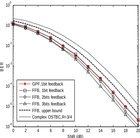
fading channels. In Figure 1, we plot the bit error rate
(BER) performance of the generalized partial feedback based OSTBC scheme in [7,8] (“GPF” for short ) and the proposed flexible feedback bits scheme (“FFB” for short)
with n pT 4 transmit antennas. For this case p2,
and the GPF scheme can only feedback 1 bit, whereas the proposed scheme can feedback more bits to improve the
system performance. For comparison, in Figure 1 we
also give the BER figures of the complex orthogonal code for four transmit antennas [11], and the numerical results of the upper bound in (24) of the proposed
scheme. Figure 1 shows that with 1 bit feedback, the
GPF and FFB schemes have close performance, whereas the FFB scheme has better performance with more feed-back bits. In comparison to the complex orthogonal code, both two schemes have better performance.
In Figure 2, the BER performance of the two schemes
with n pT 8 transmit antennas is depicted. For this
case p4, and the GPF scheme can only feedback 3
bits, whereas the proposed FFB scheme can feedback more bits. We can observe that with the same feedback bits 3, the two schemes have very similar performance, and with more feedback bits, the proposed FFB scheme can further improve the performance. In the simulations of these two schemes, the exhaustive search over all pos-sible feedback vectors is used.
0 2 4 6 8 10 12 14 16 18 20
10-6 10-5 10-4 10-3 10-2 10-1 100
SNR (dB)
BE
R
[image:4.595.310.536.215.437.2]GPF,1bit feedback FFB, 1bit feedback FFB, 2bits feedback FFB, 3bits feedback FFB, upper bound Complex OSTBC,R=3/4
Figure 1. BER performance of the two schemes with nTp = 4
transmit antennas.
0 2 4 6 8 10 12 14 16
10-6 10-5 10-4 10-3 10-2 10-1 100
SNR (dB)
BE
R
[image:4.595.311.536.479.705.2]GPF,3 bits feedback FFB, 3 bits feedback FFB, 4 bits feedback FFB, 6 bits feedback
Figure 2. BER performance of the two schemes with nTp = 8
6. Conclusions
In this paper, we proposed a partial feedback based OSTBC scheme with flexible feedback bits. The new scheme inherits the OSTBC properties of achieving full diversity, preserving low decoding complexity, and has full rate. Moreover, compared with the conventional par-tial feedback based OSTBC schemes, the new scheme can support flexible feedback bits and can improve the system performance with more feedback bits.
REFERENCES
[1] V. Tarokh, H. Jafarkhani and A. R. Calderbank, “Space-time Block Codes from Orthogonal Designs,” IEEE Transactions on Information Theory, Vol. 45, No. 5, 1999, pp. 1456-1467.doi:10.1109/18.771146
[2] S. M. Alamouti, “A Simple Transmitter Diversity Scheme for Wireless Communications,” IEEE Journal on Selected Areas in Communications, Vol. 16, No. 8, 1998, pp. 1451-1458.doi:10.1109/49.730453
[3] S. Sandhu and A. J. Paulraj, “Space-time Block Codes: A Capacity Perspective,” IEEE, Communications Letters, Vol. 4, No. 12, 2000, pp. 384-386.
doi:10.1109/4234.898716
[4] H. Jafarkhani, “A Quasi-orthogonal Space-time Block Code,” IEEE Transactions on Communications, Vol. 49, No. 1, 2001, pp. 1-4.doi:10.1109/26.898239
[5] W. Su and X. G. Xia, “Signal Constellations for Quasi- orthogonal Space-time Block Codes with Full Diversity,” IEEE Transactions on Information Theory, Vol. 50, 2004, pp. 2331-2347. doi:10.1109/TIT.2004.834740
[6] X. L. Ma and G. B. Giannakis, “Full-diversity Full-rate Complex-field Space-time Coding,” IEEE Transactions
on Signal Processing, Vol. 51, No. 11, 2003, pp.
2917-2930.doi:10.1109/TSP.2003.818206
[7] J. Akhtar and D. Gesbert, “Extending Orthogonal Block Codes with Partial Feedback,” IEEE Transactions on
Wireless Communications, Vol. 3, No. 6, 2004, pp.
1959-1962.doi:10.1109/TWC.2004.837469
[8] A. Sezgin, G. Altay and A. Paulraj, “Generalized Partial Feedback Based Orthogonal Space-time Block Coding,” IEEE Transactions on Wireless Communications, Vol. 8, No. 6, 2009, pp. 2771-2775.
doi:10.1109/TWC.2009.080352
[9] B. Hassibi and B. M. Hochwald, “High-rate Codes That Are Linear in Space and Time,” IEEE Transactions on Information Theory, Vol. 48, No. 7, 2002, pp. 1804-1824. doi:10.1109/TIT.2002.1013127
[10] M. K. Simon and M. S. Alouini, “Digital Communication over Fading Channels,” John Wiley & Sons Inc., 2000.