Brain Signals Extraction for the Control of a Prosthetic Hand
Prof.Kais Aboud1, Dr.Eng.Mohamad Ayham Darwich2 & Eng.Shadi Ali3
1Professor in Department of Industrial Automation, Faculty of Technical Engineering, Tartous University, Syria. 2Associate Professor, Department of Industrial Automation, Faculty of Technical Engineering, Tartous University, Syria. 3Scientific Student –Master, Faculty of Technical Engineering, Tartous University, Syria.
Article Received: 19 October 2018 Article Accepted: 27 February 2019 Article Published: 23 May 2019
1. INTRODUCTION
Brain-computer interfaces (BCI) technology helps researchers in building a communication channel between
human brain and computer [1]. Neuroscience has shown that 100 billion nerve cells in the human brain,
characterized by electrochemical properties, can be measured and described by six forms of brain waves (Delta-
Theta- Alpha- Beta- Gamma- Mu) [2]. For example, the change in alpha wave activity in terms of maximum
frequency and wave propagation, as well as the frequency band in which this wave exists, can be observed as a
response to the opening and closing of the eye [3].
The communication channel between brain and computer provides the possibility of transmitting information in
form of electrical signals. The general principle is to read electrical activities from the brain using non-invasive
electrodes (non Invasive BCI) or on the surface of the brain directly (Invasive BCI) [4], which helps in obtaining
the needed information for the analysis and the classification of the waves, and then produce the controlling
command and recover the lost functions.[5]. Research in this area began in the 1970s at the University of
California, Los Angeles, as part of a grant from the National Science Foundation, where researchers Arnaud
Delorme and Scott Makeig (2004) developed a toolbox and graphical interface called (EEGLAB), Built in a matlab
environment for the purpose of reading and processing brain signals [6].
In 2011 (Arnaud et al.) developed a set of tools (NFT, SIFT, BCILAB, ERICA) which facilitated the acquisition
and processing of EEG signals [7]. In 2014, the research group [Lavanya et al] studied the possibility of developing
a robot capable of helping handicapped people in performing their daily tasks without the help of others, but this
study did not dealt with the development of signal processing algorithms and the construction of the control
command [8].
A B S T R A C T
Brain computer interface was designed to acquire brain signals and connecting it to labview via Bluetooth technology. 10 persons were participated and performed eyes blinking and head tilting at same instants according to a predetermined timing protocol, and signal acquisition was performed using different offline and online strategies.
A first algorithm was developed to denoise and segment the signals. Amplitude changes were analyzed to define the distinguishing thresholds between rest and movement cases. After the analysis and the classification steps, a third algorithm was developed to send the command data to an Arduino chip.
EEG signal amplitude changes were noted during eyes blinking and the movement of the head. The reliability of the results was verified, and the controlling command was generated and conducted successfully to the Arduino circuit.
Nafea et al, (2018) designed a smart home control system to help handicapped and older people in performing daily
functions. The system consisted of Neurosky EEG acquisition system, associated to an Android application, which
was developed to control four home applications [9]. Geethu Suresh, S.Shanmugaraju,(2016) designed a wireless
control system to trigger wheelchair via brainwave mobile sensors. Electrical signals were read and sent as
Bluetooth packets. The signal was processed in Matlab using a short time Fourier transform to remove noise and
send commands to an ARM7 microcontroller driving DC motors of the wheelchair [10]. Harmony Tan Shi
Le,(2015) used the electroencephalographic (EEG) using wet Ag/Agcl electrodes positioned at six locations on the
scalp (Fp1, Fp2, C3, C4, O1, O2). This study adopted a specific timing scenario to record EEG signals (two minutes
of closed eyes - two minutes of open eyes), and then a set of eyes closing and opening was repeated 10 times (5
seconds open eyes - 5 seconds closed eyes). The study highlighted the increase in alpha wave activity during eye
closure [11]. Qiang Gao et al,(2017) designed an EEG-EMG-BCI hybrid system, which consisted of three sections
(Emotiv EPOC - host computer - robotic arm). The goal of the system was to acquire signals in real time to reduce
the delay and enhance patient’s interaction. Brain and muscle signals were recorded to produce a control command upon patient’s intention and teeth occlusion. Signals were processed and decrypted using web-based controllers
based on DWT. The control command was sent wirelessly to the arm to draw the word imagined by the patient [12].
Madhu Nakirekanti et al,(2017) designed a two-wheeled robot and control its movement in three directions
(front-left-right) via an ARM controller driving DC motors. The processor is controlled by a communication
interface built in a MATLAB environment. The computer was receiving data from the mind waves through a
Bluetooth module. The data included information about the intensity of the signal during eye blinking, which was
processed and sent to an ARM controller for action execution and robot movement [13].
Anupama et al,(2014) designed a brain-computer interface to control a wheelchair of a disabled person. Brain
waves were captured and sent to a Labview program, which was processing them using short-Fourier transform to
classify the signals during patient concentration and eye blinking. The command was sent through the RS232
connection port and the MAX232 circuit switched to a MSP430G2231 controller that used PWM technology to
drive the moving motors [14].
This research aims to read brain signals and use them as a controlling command. This implies the analysis and the
recognition of these signals, based on different features in order to raise the reliability of the command upon the
movement and the intention of the patient.
2. OBJECTIVE AND IMPORTANCE OF THE RESEARCH
This study is dealing with the possibility of converting brain signals into a controlling command, depending on the
following sub-objectives:
1. Record brain signals using an offline and online scenarios.
2. Build a brain signal denoising and segmentation algorithms
4. Foster the control command via the use of the angle of the head.
5. Send the control command to an external electronic circuit.
This research is hoped to open a new door in the neuro-technology and the recording and analysis of brain signals,
which has recently become the focus of interest of most research centers in the world, and it aims to compensate the
loss of limb using biological signals generated from remaining organs.
3. MATERIALS AND METHODS
The practical stages of the application consist of four main parts (figure 1):
1. Signal Acquisition.
2. Signal processing.
3. Feature extraction and classification.
4. Control of a prosthetic arm.
Fig.1 Steps of EEG command generation
3.1 Signal acquisition
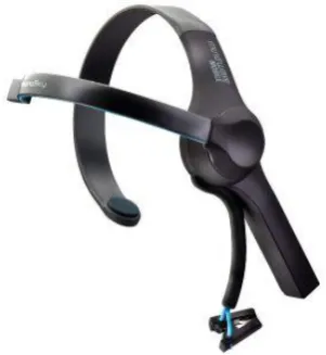
In this research, a Neurosky device (NeuroSky, Inc., USA) was used to acquire EEG signals and then transmit them
to a computer via Bluetooth protocol (figure 2). Neurosky device was chosen due to the following specifications:
- Correct signal detection with good noise elimination.
- Simple to use, it contains one EEG channel + Reference + Ground. - Advanced filtering to reduce noise.
- RAW EEG sampling rate at 512Hz.
- Flexible voltage supply within the range of 2.97 to 3.63 volts. - Frequency response range: 3-100 Hz
A gyroscope sensor (GY-88, Arduino, Italy ) was also used to determine the angle of head in order to foster the
obtained control command.
Fig.2 NeuroSky EEG acquisition device
3.2.Signal processing
Acquired signals were filtered in order to eliminate noise of eyes muscles movement. Cutoff frequencies were set
according to EEG frequency bands shown in table (1):
Table (1): EEG signals characteristics [11]
3.2.1. Offline processing scenario
Labview was used as the main environment to develop the processing and the interfacing algorithms between
different steps. Signal processing algorithm was composed of the following sub-steps, as shown in Figures (4) and
1. Reading raw values: a subroutine was developed to read the raw values registered in a text file. The values were
read and converted to a 2D binary matrix composed of integers.
2. Index array: This step was converting the binary matrix into a single matrix.
3. Butterworth filtering: This filter was used to eliminate noise signals and determine the bandwidth of each wave.
4. Graph chart: This tool was adopted to show the brain waves before and after filtration.
Fig.4 Signal reading and denoising algorithms
Fig.5 Signal reading and noise isolation program Read brain
signal and convert it to a
two-dimensional
matrix
Converts the binary matrix into a single
matrix
Signal filtering and noise reduction
3.2.2. Online processing scenario
The second phase of signal analysis was based on a Neurosky device and linked to Labview via Bluetooth
technology, which required a direct linking between Labview and Neurosky library containing the following tools,
as shown in the Figure (6):
Fig.6 Neurosky and Labview drivers
A second program was developed to read brain signals in the labview environment using Neurosky tools. The
program allowed the reading of brain signals from the Neurosky device via Bluetooth technology. Signal strength
and quality were checked and displayed on the main frame of the program. Data was allowed to be saved to a
specific file in order to be used in next stages. Signal was filtered and displayed on the Graph chart screen, as shown
in Figures (7) and (8):
Fig.7 Brain signal reading algorithm. Read the brain
signal from the Neurosky
device
Check the quality of the
connection
Determination of sampling time and signal
filtration
Displays the signal on a
Fig.8 Brain signal reading program
Gyroscope sensor samples were also read and sent directly to the Arduino program.
3.3.Feature Extraction
EEG signals have been translated into a number of features which were categorized by task . Some movements were
performed and the immediate changes of the signal's amplitude were observed, as shown in Figure (9).
To evaluate the reliability of the results, the experiment was repeated ten times on 10 different subjects, and signal
changes were noted during eye blinking according to a predetermined timing protocol:(5 seconds rest – eye
blinking - 5 seconds rest – eye blinking two times - 5 seconds rest with eye opening).
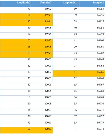
The reproducibility of the results was checked by exporting EEG signal to an Excel file and tracking amplitude
changes following the timing sequence as shown in Table 2 containing signal changes of one of recorded signals.
The first column represents the time and the second column represents signal's amplitude. Gray shadows indicated
the cases of eye blinking.
Table (2): signal amplitude changes versus time.
86981 45 87013 96 86982 24 87014 77 86983 24 87015 29 86984 54 87016 -7 86985 77 87017 -7 86986 66 87018 -11 86987 49 87019 -25 86988 27 87020 -9 86989 18 87021 20 86990 21 87022 34 86991 37 87023 39
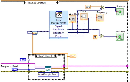
Signal variations tracking showed an increase in amplitude during eye blinking, and these changes have been
invested to set the threshold values. Tone Measurements were used to measure the frequency, amplitude and angle,
then to compare the amplitude with the found threshold values and to generate the control command. A value
greater than 81 was found to correlate with eye blinking, and is used to generate command signal, as shown in
Figure (10).
3.4. Control of the machine
In this step, a control signal was sent from the computer to the machine to be controlled based on the generated
controlling signal generated from the previous step.
The control program was built and linked to the data collection program that was previously built. Consequently, a
case structure loop was developed to send the 'b' character to the Arduino circuit when signal value exceeds the
determined threshold.
Fig.11 Control program
The Arduino chip was programed to receive the control command that was built in the previous stage. A specific
chip program was written to read gyroscope and EEG signals and activate an electrical relay when receiving the 'b'
character.
4. RESULTS AND DISCUSSION
In this research:
1. Recording of brain signals by Neurosky device and linking it with Labview
2. Build an algorithm to read the brain signal
3. Conducting experiments on different persons to observe the signals changes during eye blinking.
4. The generation of a control command according to a specific change in the amplitude of the brain signal
5. Strengthen the control command by using the angle of the head ache
6. Send the control command to the Arduino slide to move an arm according to the blink of the eye and the angle
of the head ache.
While the reviewed studies did not adopt the same devices and scenarios to acquire brain signals, we tested our
foster the command signal and resulted in an enhanced reliability when analyzing statistical data associated to the
generation of the command signal.
5. CONCLUSIONS AND RECOMMENDATIONS
Brain signals have been analyzed and classified in specific situations and the possibility of command controlling
signal was checked. This command can be used to move a robotic arm or an artificial limb. The results of this paper
can be extended by studying signal variations during other activities and the same algorithms can be modified to
generate the command signal using other biological signals.
We recommend the use of more advanced EEG acquisition devices in order to enhance the resolution and prevent
the undesired movements.
REFERENCES
[1] Bularka, S., & Gontean, A. (2016). Brain-Computer Interface review, in: 2016 12th International Symposium
on Electronics and Telecommunications, ISETC 2016 - Conference Proceedings, pp. 219–222.
[2] Baldi, K. A. (2018). The Generation of Brain Waves. American Journal of EEG Technology, 21(4), pp.
187–190.
[3] Sanei, S., & Chambers, J. A. (2013). EEG Signal Processing.
[4] Ramantani, G., Maillard, L., & Koessler, L. (2016). Correlation of invasive EEG and scalp EEG. Seizure, 41,
pp. 196–200.
[5] Bright, D., Nair, A., Salvekar, D., & Bhisikar, S. (2016). EEG-based brain controlled prosthetic arm, in:
Conference on Advances in Signal Processing, CASP 2016, pp. 479–483
[6] Delorme, A., & Makeig, S. (2004). EEGLAB: an open source toolbox for analysis of single-trial EEG
dynamics including independent component analysis. Journal of neuroscience methods, 134(1), pp. 9–21.
Retrieved from
[7] DELORME,A;MULLEN,T;KOTHE,C;ACAR,A,Z;SHAMLO,N,B; VANKOV,A; and
MAKEIG,S.(2011),EEGLAB, SIFT, NFT, BCILAB, and ERICA: New Tools for Advanced EEG
Processing.California San Diego,12.
[8] THUNUGUNTLA,L;MOHAN,R,V;MOUNIKA,P.(2014),EEG Based Brain Controlled Robot.India,4.
[9] Marwan Nafea, Amirah ‘Aisha Badrul Hisham, Nurul Ashikin Abdul-Kadir and Fauzan Khairi Che Harun
.(2018), Brainwave-Controlled System for Smart Home Applications. (ICBAPS) 6
[10] Geethu Suresh, S.Shanmugaraju .(2016), E-Sense Algorithm Based Wireless Wheelchair Control UsingBrain
Waves. (IOSR-JEEE).8
[12] Qiang Gao, Lixiang Dou, Abdelkader Nasreddine Belkacem, and Chao Chen.(2017), Noninvasive
Electroencephalogram Based Control of a Robotic Arm for Writing Task Using Hybrid BCI System.9
[13] Madhu Nakirekanti, Dr. Raja Murali Prasad, Eliyaz Mahammad and K. Narsimha Reddy.(2017), BRAIN
WAVE CONTROLLED ROBOT USING MATLAB. (IJMET).10
[14] ANUPAMA H. S, N. K. CAUVERY & LINGARAJU G. M.(2014), BRAIN CONTROLLED
WHEELCHAIR FOR DISABLED. (IJCSEITR).10
[15] Tharani.k, Tharanitharan.B, Vinnarasu.K.N, Vinothkumar.G.(2019), BRAIN-BASED
COMPUTERINTERFACES IN VIRTUAL REALITY,8.
[16] Prashanth Kambli, Lingaraju G M.(2015), Robot Control using Brain Waves.4
[17] Rabie A. Ramadan, S. Refat, Marwa A. Elshahed and Rasha A. Ali.(2015), Basics of Brain Computer
Interface.21
[18] Upendra Kumar Bhusan, Manish Yadav, Sumit Bharagava.(2015), EEG Analysis for Brainwaves under
Closed Eye and Open Eye.5
[19] BAZANOVA,O,M;VERNON,D.(2013),Interpreting EEG alpha activity. Holland,12
[20] ONTON,J;DELORME,A; and MAKEIG,S.(2005), Frontal midline EEG dynamics during working memory.