Vol. 1, No. 1, pp. 71-80, June (2018)
Torque Ripple Minimization in SRM Based on Advanced Torque Sharing
Function Modified by Genetic Algorithm Combined with Fuzzy PSO
Hassan Moradi CheshmehBeigia)andAlireza Mohamadi Amidib)
This paper presents a new and improved Torque Sharing Function (TSF) to minimize torque ripple of Switched Reluctance Motor (SRM). This approach combined of three steps. At first step, Genetic Algorithm has been used to define the best Turn-on and Turn-off angel of phase current. At second step, a fuzzy logic controller system has been designed as a new TSF. Finally, at the last step, Particle Swarm Optimization (PSO) has been used to optimize Fuzzy membership function. The two main merits of this approach are that the proposed control algorithm can be used in wide speed ranges and also three-step-design and optimization makes this approach enable to perfectly results in smooth torque. The effectiveness of this approach has been verified through a simulation of four phase 8/6 SRM in Matlab/Simulink. Obtained result from simulation shown that the produced torque was high quality and its ripple was one-third of fuzzy TSF. This proposed method is very powerful to adapt itself for various kind of SRMs with different parameters.
A B S T R A C T
ARTICLE INFO
Keywords:
SRM
Torque Sharing Function Ripple Minimization Fuzzy Interface System
Article history:
Received March. 7, 2018 Accepted May. 1, 2018
I. INTRODUCTION
Switched Reluctance Motors (SRM) has gained atten-tion from industry and researchers due to its simple struc-ture, lack of use of magnet or winding on rotor, high power density, and low operation cost1. However, due to salient pole of stator and rotor, SRM have the problem of high torque ripple2. When a pole is transferring from
one phase to another phase, a big torque ripple occurs which makes oscillation in rotor speed and a big sound noise. Usually, there are two main approaches in regard to the ripple minimization of SRM. The first approach is a proper mechanical design of rotor and stator, and the second approach is the control method3. In4 and5,
me-chanical design has been combined with control approach to reduce torque ripple and produce constant torque.
One of the most convenient approach to reduce torque ripple is to share torque of incoming phase and outgoing phase. This approach is called Torque Sharing Function (TSF). TSF defines a torque shape in overlap area of
a)Corresponding Author: [email protected], Tel:
+98-833-4274530, Fax: +98-833-4274542, Electrical Engineering, Razi Uni-versity, Kermanshah, Iran
b)Electrical Engineering, Razi University, Kermanshah, Iran
http://dx.doi.org/10.22111/ieco.2018.24302.1016
incoming and outgoing phase, and the phase should pro-duce the referenced torque assigned by the TSF. Some of the primary approaches of TSF are linear, cubic, co-sine, and exponential type of TSF used in the literature6. However, these TSF implementation are very simple, but they do not improve torque profile so much. In7, an
op-timization algorithm is used to minimize torque ripple. In8, an online logical TSF is introduced to improve torque
profile. This is claimed the logical TSF changes accord-ing to the situation. However, flux range change in this approach is very high and the stator loss is a lot.
Due to the nonlinearity of SRM,9 and10 proposed
an iterative learning approach to minimize torque rip-ple. Ref11 presents a novel DTC strategy for a
six-phase transverse flux permanent magnet motor. Ref12 introduces a novel magnetically isolated phase structure for switched reluctance motor, namely, as SeptiSegment SRM, which is proper for high torque/volume and with lowest leakage flux in different fields of industries. In13,
a fuzzy TSF has been proposed to control phase torque. This approach has been tested on a 12/8 SRM, but the result is not that good in motor with lower rotor/stator pole.
vk =Rsik+ k r
dr (1)
in Eq. (1), linkage flux of each phase is λk(θr·i) =
L(θri)ik. So we have:
vk =Rsik+L(θr·i)
dik
dr +
dL(θr·i)
dθr
ωrik (2)
whereωris angular speed of the rotor. In a linear
mag-netic area, co-energy can be defined as follows:
Wc = Z
λdi (3)
T(i·θ) = ∂Wc ∂θ = ∂ ∂θ Z t 0 λdi (4)
Eq. (4) can be written as follows15:
T(i·θ) =1 2i
2dL
dθ (5)
Eq. (5) shows that instantaneous torque is proportional to the square of current and instantaneous change of in-ductance. Also, the total instantaneous torque of a SRM is achieved by sum of each phase torques:
Te= m X
k=1
Tk(i·θ) (6)
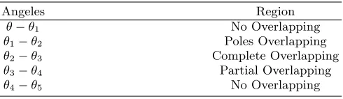
According to the Fig. 1, when inductance slop is positive and there is a current in the related phase, a positive torque is produced and when the slope is zero, the output torque is zero. Also, when the slope is negative, phase current should be zero, otherwise it produces negative torque. Four distinct induction regions emerge is given in TableI.
B. TORQUE SHARING FUNCTION
In this paper, TSF control structure is used to share torque between commutation intervals. A constant torque can be produced if torque sharing between in-coming and outgoing phase is well introduced. Due to the lack of torque during commutation interval, TSF can be used to keep the produced torque constant. The de-sign of TSF is very important, otherwise it can result is higher torque ripple. The proper sharing of torque can
Angeles Region
θ−θ1 No Overlapping
θ1−θ2 Poles Overlapping
θ2−θ3 Complete Overlapping
θ3−θ4 Partial Overlapping
θ4−θ5 No Overlapping
remove torque ripple in SRM. So, torque request should be distributed between two phases16. The torque can be
written as a sum of two phases suchxandy:
Te∗=Tx∗+Ty∗ (7)
where:
Tx∗ =Te∗∗fx(θ) (8)
Ty∗=Te∗∗fy(θ) (9)
wherefx(θ) and fy(θ) are the xand y TSF. In
commu-tation intervalθi is start angel and θf is final angle for
commutation interval. For instance, for a four phase 8/6 SRM, we have:
15◦> θf > θi ≥0◦ (10)
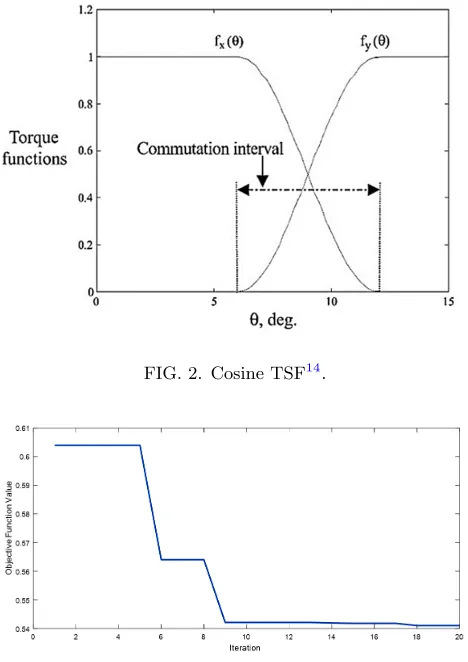
In17, a cosine TSF was proposed whichfxandfy
func-tions are as follows:
fx(θ) =
1 f or 0◦≤θ≤θi
1 +cosk(θ−θi)
2 f or θi ≤θ≤θf
0 f or θf ≤θ≤15◦
(11)
fy(θ) =
0 f or 0◦≤θ≤θ
i
1 +cosk(θ−θi)
2 f or θi≤θ≤θf
1 f or θf ≤θ≤15◦
(12)
where:
k= 180 θf−θi
FIG. 2. Cosine TSF14.
FIG. 3. GA convergence for tuning the best angles.
The TSF schematic is illustrated in Fig. 2. It should be mentioned that rising and falling shape of Fig. 2 is going to be replaced by FIS. There are two fuzzy systems, which one of them is for rising part of incoming phase and the second fuzzy is for falling part ofoutgoing phase.
III. PROPOSED METHODS
In this section, GA, Fuzzy Interface System and PSO algorithm are explained in summery.
A. GENETIC ALGORITHM
GA is an evolutionary algorithm inspired by natural selection18. The algorithm repeatedly modifies its
pop-ulation base on three main process. The first process is named selection, by which two parents are chosen to breed a new generation. This selection is upon on a fitness-based process. In the second step, crossover is done to change the programing of the chromosome. In the third part, mutation is done to keep genetic diversity19.
FIG. 4. Input membership function for rising FIS.
FIG. 5. Output membership function for rising FIS.
B. FUZZY INTERFACE SYSTEM
Fuzzy inference is the process of formulating the map-ping from a given input to an output using fuzzy logic. It was introduced by Lotfi Zadeh in 197320. Fuzzy inference
system includes 4 important parts including fuzzification, membership function, if-then rules and fuzzy logic oper-ators, and defuzzification. There exist two types of fuzzy inference system i.e. Mamdanis fuzzy inference method21
and Sugeno-type fuzzy inference system22. Mamdani’s
method is the most popular fuzzy method. It was pro-posed in 1975 by Ebrahim Mamdani as an attempt to control the flow of steam engine and boiler by creating a set of linguistic control rules obtained from experienced human operators23. In this paper, the researchers
knowl-edge has been used to build the initial fuzzy and then, PSO has been applied to optimized fuzzy membership functions.
1. MEMBERSHIP FUNCTION
FIG. 6. Input membership function for falling FIS.
FIG. 7. Output membership function for falling FIS.
has one input and one output. GA has been used to de-fine the best starting and ending fire angle of the phases. The best turn-on angel for the 8/6 SRM, which has been used here, is 32◦ and the best turn-off angel is 47◦. GA determines 5◦ as a best commutation interval. GA con-vergence is depicted in Fig. 3. GA calculates these angles base on the fact that the torque ripple is kept in lowest value. So for the rising FIS, the membership functions of input and output are depicted in Fig. 4 and Fig. 5, respectively. Also, for the falling FIS, the membership functions of input and output are depicted in Fig. 6 and Fig. 7, respectively. The above-mentioned membership functions and their rules are designed so that the initial behavior of FIS follow the FIS behavior of Ref13. Then they will be upgraded and optimized.
2. FUZZY RULES
Falling and rising FIS has different rules, and the rules have been defined based on authors experience. The rules of rising FIS is given in TableII. As the rotor approaches the incoming phase, the rules and membership values for rising FIS gains importance and the authors define more rules when rotor is closing to the phase. The rules of falling FIS is given in Table III. In the falling FIS, the authors define more rules in middle and end of commuta-tion interval since falling FIS value in this region is more important.
TABLE III. Falling FIS rules
Rules Input MF Output MF Rule
Number Name Name Weight
1 Mf1 Mf3 1
2 Mf2 Mf2 1
3 Mf3 Mf1 1
4 Mf2 Mf3 1
C. PARTICLE SWARM OPTIMIZATION
The PSO is chosen as optimization algorithm since its results are so accurate and does not need complex calculation24,19. Also base on previous works on fuzzy
optimization, PSO can optimize fuzzy membership func-tion more accurately and quickly in comparison to other algorithms25. Different literature is explained PSO in detail26,27.
In the basic PSO technique, suppose that the search space is d-dimensional,
1. Each member is called particle, and each particle (i -th particle) is represented by d-dimensional vector and described asXi= [xi1, xi2,· · ·, xid].
2. The set of n particle in the swarm are called popu-lation and described aspop= [x1, x2,· · ·, xn].
3. The best previous position for each particle (the po-sition giving the best fitness value) is calledparticle best and described asP Bi= [pbi1, pbi2,· · ·, pbid].
4. The best position among all of the particle best position achieved so far is called global best and described asGB= [gb1, gb2,· · ·, gbd].
5. The rate of position change for each particle is called the particle velocity and described as Vi =
[vi1, vi2,· · ·, vid].
At iteration k the velocity for d-dimension of i -particle is updated by:
vk+1id =wvidk +c1r1(pbkid−X k
id) +c2r2(gbkd−X k id) (14)
wherei= 1,2,· · ·, nandnis the size of population, w is the inertia weight, c1 and c2 are the
accel-eration constants, and r1 and r2 are two random
6. The i-particle position is updated by
Xidk+1=Xidk +Vidk+1 (15)
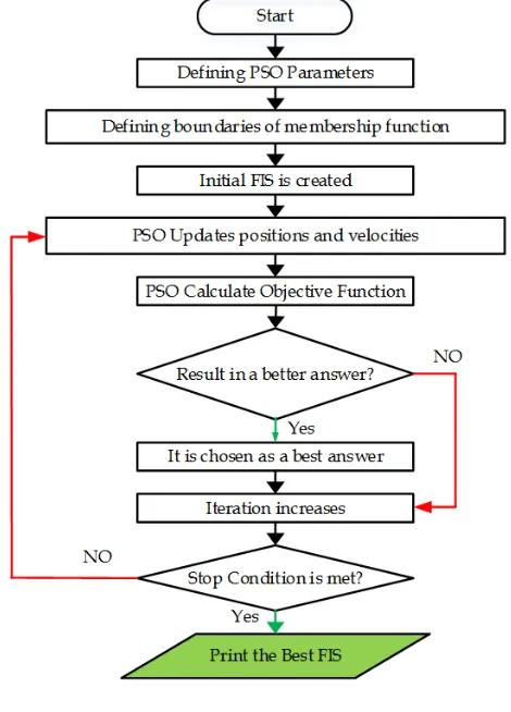
Flow chart of optimization is shown in Fig. 8. The flowchart works as follows:
1. PSO parameters are determined
2. Boundaries of center and sigma of membership functions are defined.
3. The Fuzzy Inference System (FIS) is initialized.
4. PSO updates its positions and velocities.
5. PSO runs MATLAB/Simulink and provide it with a new FISs. After simulation, PSO calculates the objective function value.
6. If this new FIS results in a better answer, it is con-sidered as a best FIS up to now.
7. If stop condition is not met, go to step 4.
8. Print the results.
D. CONTROL STRUCTURE
Control structure used in this paper is shown in Fig.
9. There is a PI controller to track reference speed by defining torque reference. Torque is mapped by a lookup table to current reference. Also, there is an encoder to determine rotor position. on and off and rotor
posi-tion are provided to the TSF box to determine reference shape. TSF box can be a simple shape with no over-lap, a Cos TSF, Fuzzy TSF, and optimized Fuzzy TSF. The current refe rence is then achieved by multiplying the current reference value in TSF shape. A hysteresis controller is also used to track the current by turning on and off the IGBTs of converter.
IV. FUZZY TRAINING AND NUMERICAL STUDY
To validate the proposed method, the system has been simulated in Matlab/Simulink. Also, Matlab/mfile has been used to execute code for PSO, GA, and FIS. A four phase 8/6 SRM is used to validate the results. Motor pa-rameters are given in TableIV. To compare the effective-ness of the proposed method, the results have been com-pared with a Cosine TSF17and a Fuzzy Logic Controller
designed in13. The following is divided into two parts.
In the first part, PSO has been employed to tune fuzzy membership functions of both the rising and falling FIS, and in the second part, the results of proposed method are compared to results of two papers.
FIG. 8. Optimization flowchart.
TABLE IV. Motor parameters
Dc-Link Voltage 300V
Stator Resistance 0.05 Ω
InductanceLmin 0.1mH
InductanceLmax 0.5mH
Stator Pole Number 8
Rotor Pole Number 6
A. FUZZY TRAINING USING PSO
FIG. 9. Control structure.
overall torque function
Torque function =
Rising FIS, θ1< θ < θ2
(1 +k1(θ−θ3)k2), θ2< θ < θ3
Falling FIS, θ3< θ < θ4
(16)
where 3 is the turn off angel. Also, PSO has been used
in parallel to the tuning of the FIS membership function to define k1 and k2. After optimization k1 and k2 is
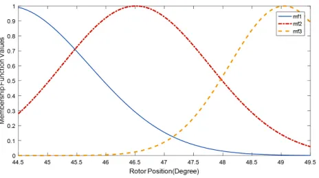
set to 0.13 and 3.14 respectively. Optimization objective function Eq. (17) is minimizing of the Torque Ripple (TR) Eq. (18):
OF =
Z t
0
(TR)2dt (17)
TR = (Tmax−Tmin Tav
) (18)
where TR is torque ripple andtis simulation time. The PSO population and iteration have considered 20 and 30, respectively. Objective function value during optimiza-tion process is shown in Fig. 10.
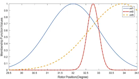
Input and output membership function of rising FIS after optimization are shown in Fig. 11 and12, respec-tively, and for falling FIS is shown in Fig. 13 and 14, respectively.
B. NUMERICAL STUDY AND RESULTS COMPARISON
To evaluate the effectiveness of the above mentioned method, this method has been compared with two meth-ods. The first method is cosine TSF17 and the second method is fuzzy TSF which has been proposed in13. The load torque is 1N mand the reference speed is 1000rpm.
FIG. 10. Objective value during optimization period.
FIG. 11. Input membership function for rising FIS after op-timization.
Fig.15shows that all of the three methods track the ref-erence speed very well. Torque distribution of these three methods i.e. cosine TSF, Fuzzy TSF, and proposed Fuzzy PSO TSF are depicted in Fig. 16. Torque ripple (inpu) is shown in Fig. 17for these three methods. Also, for a closer look, see Fig. 18.
respec-FIG. 12. Output membership function for rising FIS after optimization.
FIG. 13. Input membership function for falling FIS after op-timization.
tively. Fig. 19 and Fig. 20 show speed tracking and ripple torque for the speed of 500. Also, for 1500 rpm speed tracking and ripple torque are shown in Fig. 21
and Fig. 22, respectively.
C. DISCUSSION
As can be seen in Fig. 15, speed tracking of these three methods are very well. There are differences in TSF of these three method. The first cosine TSF is smooth, but it makes a big torque ripple. The second method,
FIG. 14. Output membership function for falling FIS after optimization.
FIG. 15. Speed tracking of three methods.
FIG. 16. Torque distribution (pu) shape in three TSFs.
i.e. fuzzy TSF, which is proposed in13, is very good for
three phase 12/8 SRM motor, but it makes large torque ripples when it comes to implementation for SRM with lower/higher poles (or simply for different SRM). For in-stance, the proposed fuzzy TSF does not result in a good torque as the poles of SRM decreased. As can be seen in Fig. 17and Fig. 18, torque ripple of fuzzy TSF for four phase 8/6 is about 0.25pu (or 25%), however it gives a better result for three phase 12/8 SRM.
The proposed method in this paper can result in a better answer since it enjoys two optimization algorithm
FIG. 18. Closer look to the torque ripple (pu) in cosine, fuzzy, and fuzzy PSO TSF.
FIG. 19. Speed tracking of three methods for 500rpm.
i.e. GA for starting and ending point of phase pulse and PSO for training fuzzy interface system. The proposed approach gives less than 0.07 pu (or 7%) torque ripple which is about one-third of the previous method. Also, it can be applied to any SRM, with any poles and phase and with any parameters. The proposed method can find the best TSF, since it enjoys two powerful optimiza-tion algorithm that can find the best TSF for any SRM. Moreover, in a closer look to Fig. 15, it can be seen that there is an increase in value of the torque reference in part in which a rotor pole is under a stator phase. The reason behind this is that, we are going to accelerate the rotor until compensate lack of the torque in commuta-tion interval. This increase is given in Eq. (14). This feature can be considered as another tuning parameter which can improve torque response in different SRMs. Also, in Fig. 16, it is obvious that there is a phase shift in starting point of torque reference in the third method. This is because of GA has tuned the on and turn-off angel as new values for the phase torque/current to reduce torque ripple. For a better comparison a criterion is defined as follows to compare the results:
C= 100× Z 0.5
0.1
(TR)2dt (19)
FIG. 20. Comparison of torque ripple (pu) in cosine, fuzzy, and fuzzy PSO TSF.
FIG. 21. Speed tracking of three methods 1500rpm.
Which TR is torque ripple (in pu). This criterion for these three method is given in TableV. As can be seen, the proposed method improves torque ripple better than fuzzy TSF proposed in13, and also better than Cosine
TSF as proposed17. Criterion values for different speeds
are given in Table V. It shows that the proposed fuzzy PSO gives lower torque ripple with any speed.
V. CONCLUSIONS
Due to the various merits of SRM, it has gained attention these days. The main drawback of the SRM is
TABLE V. Criterion value for three methods
Methods Cosine Fuzzy Fuzzy Speed TSF17 TSF13 PSO Reference Criterion value 3.27 1.127 0.070 500rpm
Criterion value 3.83 1.23 0.079 1000rpm
FIG. 22. Comparison of torque ripple (pu) in cosine, fuzzy, and fuzzy PSO TSF.
its big torque ripple which causes vibrations and sound noise. In this paper, two powerful optimization algorithm i.e. GA and PSO have been combined with intelligent fuzzy interface system to define rising and falling torque sharing function as well as the increase of the part in which cosine TSF and Fuzzy TSF have been considered constant. The effectiveness of this approach has been shown in a four phase 8/6 SRM, and the produced torque was high quality and its ripple was one-third of fuzzy TSF. This proposed method is very powerful to adapt itself for various kind of SRMs with different parameters.
APPENDIX
All variables and parameters used in this paper are given in TableVI.
REFERENCES
1M. Tursini, M. Villani, G. Fabri and L. Di Leonardo, “A
switched-reluctance motor for aerospace application: Design, analysis and results,”Electric Power Systems Research, Vol. 142, pp. 74-83, 2017.
2X. Cao, Q. Sun, C. Liu, H. Zhou and Z. Deng, “Direct control of
torque and levitation force for dual-winding bearingless switched reluctance motor,”Electric Power Systems Research, Vol. 145, pp. 214-222, 2017.
3J. J. Wang, “A common sharing method for current and
flux-linkage control of switched reluctance motor,”Electric Power Systems Research, Vol. 131, pp. 19-30, 2016.
4Y. K. Choi, S. Y. Hee and S. K. Chang, “Pole-shape optimization
of a switched-reluctance motor for torque ripple reduction,”IEEE Transactions on Magnetics, Vol. 43, No. 4, pp. 1797-1800, 2007.
5S.I. Nabeta, I. E. Chabu, L. Luiz, D. A. P. Correa, W. M. Da
Silva, and K. Hameyer, “Mitigation of the torque ripple of a switched reluctance motor through a multiobjective optimiza-tion,”IEEE Transactions on Magnetics Vol. 44, No. 6, pp. 1018-1021, 2008.
6J. Ye, B. Berker and E. Ali, “An offline torque sharing
func-tion for torque ripple reducfunc-tion in switched reluctance motor drives,”IEEE Transactions on Energy Conversion, Vol. 30, No. 2, pp. 726-735, 2015.
7V. P. Vujicic, “Minimization of torque ripple and copper losses
in switched reluctance drive,”IEEE transactions on power elec-tronics, Vol. 27, No. 1, pp. 388-399, 2012.
TABLE VI. Variables and parameters
Variables and parameters
vk Kth stator phase voltage
Rs Stator phase resistance
λk Linkage flux of Kth phase
θr Rotor angle
ik Kth stator phase current
ωr Angular speed of the rotor
Wc Co-energy
θi Start angel of commutation interval
θf Final angle of commutation interval
Te Sum of phase torques
Tk Torques of Kth phase
Tx X phase torques
Ty Y phase torques
fx X TSF
fy Y TSF
MF Fuzzy Membership Function
TR Torque Ripple
PSO Variables
Xi ith particle Position
GB Global best
PB Particle best
vi Particle velocity
w Inertia weight
c1 and c2 Acceleration constants
r1 and r2 Random values in range [0,1]
X Position of particle
8D.H. Lee, L. Jianing, L. Zhen-Guo and A. Jin-Woo, “A simple
nonlinear logical torque sharing function for low-torque ripple SR drive,”IEEE Transactions on Industrial Electronics, Vol. 56, No. 8, pp. 3021-3028, 2009.
9S. K. Sahoo, S. K. Panda, and J. X. Xu, “Indirect torque
trol of switched reluctance motors using iterative learning con-trol,”IEEE Transactions on Power Electronics, Vol. 20, No. 1, p. pp. 200-208, Jan. 2005.
10S. K. Sahoo, S. K. Panda, and J. X. Xu, “Iterative learning-based
high-performance current controller for switched reluctance mo-tors,”IEEE Transactions on Energy Conversion, Vol. 19, No. 3, pp. 491-498, 2004.
11A. Ghaheri, M. Milad and T. Hossein, “Sensorless Direct Torque
Control Technique for Six-Phase Transverse Flux Permanent Magnet (TFPM) Motor,”PSC, 2016.
12A. Siadatan, T. Hossein and A. Ebrahim, “Septi-segment
switched reluctance machine: design, modeling, and manufactur-ing,”International Transactions on Electrical Energy Systems, Vol. 26, No. 8, pp. 1673-1684, 2016.
13S. H. Ro, K. G. Lee, J. S. Lee, H. G. Jeong, and K. B. Lee,
“Torque ripple minimization scheme using torque sharing func-tion based fuzzy logic control for a switched reluctance mo-tor,”Journal of Electrical Engineering & Technology, Vol. 10, No. 1, pp. 118-127, 2015.
14M. Belhadi, K. Guillaume, M. Claude, H. Hala and M.
Xavier, “Evaluation of axial SRM for electric vehicle applica-tion,”Electric Power Systems Research, Vol. 148, pp. 155-161, 2017.
15P. Truong, D. Hoa, N. Flieller, N. Ky, M. Jean and S. Guy,
“Torque ripple minimization in non-sinusoidal synchronous reluc-tance motors based on artificial neural networks,”Electric Power Systems Research, Vol. 140, pp. 37-45, 2016.
16R. Krishnan, Switched reluctance motor drives: modeling,
21E. Mamdani and S. Assilian, “An experiment in linguistic
synthe-sis with a fuzzy logic controller,”International Journal of Man-Machine Studies, Vol. 7, No. 1, pp. pp. 1-13, 1975.
22M. Sugeno, “Industrial applications of fuzzy control,”Elsevier
Science Pub. Co., 1985.
23Webpage: Fuzzy Inference Systems.
24J. Kennedy, “Swarm intelligence,”In Handbook of nature-inspired
and innovative computing, Springer, Boston, MA, pp. 187-219, 2006.
25Z. Liu, C. Mao, J. Luo, Y. Zhang and C. L. P. Chen, “A
three-domain fuzzy wavelet network filter using fuzzy PSO for robotic assisted minimally invasive surgery,”Knowledge-Based Systems, Vol. 66, pp. 13-27, 2014.
26H. Karimi, B. T. H. Mohammad and R. Amin, “Decentralized
voltage and frequency control in an autonomous ac microgrid using gain scheduling tuning approach,”Electrical Engineering (ICEE), 24th Iranian Conference on. IEEE, 2016.
27K. L. Du and M. N. S. Swamy., “Particle swarm
optimiza-tion,”Search and Optimization by Metaheuristics. Springer In-ternational Publishing, pp. 153-173, 2016.
28S. K. Sahoo, S. K. Panda, and J. X. Xu, “Iterative
learning-Shahid Beheshti, Tehran, Iran, in 2007. He received his Ph.D. degrees in Elec-trical Engineering from the Shahid Beheshti, Tehran, Iran, in 2011, respectively. In 2011, he joined the University of Razi, as an Assistant Professor in the Department of Electric Engineering. His current research interests Include Novel Electric Machine, Electric Machine Drives, Power Electronic Converters/Inverter.