University of New Orleans University of New Orleans
ScholarWorks@UNO
ScholarWorks@UNO
University of New Orleans Theses and
Dissertations Dissertations and Theses
Summer 8-6-2018
Semantic-aware Stealthy Control Logic Infection Attack
Semantic-aware Stealthy Control Logic Infection Attack
Sushma kalle
University of New Orleans, New Orleans, [email protected]
Follow this and additional works at: https://scholarworks.uno.edu/td Part of the Information Security Commons
Recommended Citation Recommended Citation
kalle, Sushma, "Semantic-aware Stealthy Control Logic Infection Attack" (2018). University of New Orleans Theses and Dissertations. 2512.
https://scholarworks.uno.edu/td/2512
This Thesis is protected by copyright and/or related rights. It has been brought to you by ScholarWorks@UNO with permission from the rights-holder(s). You are free to use this Thesis in any way that is permitted by the copyright and related rights legislation that applies to your use. For other uses you need to obtain permission from the rights-holder(s) directly, unless additional rights are indicated by a Creative Commons license in the record and/or on the work itself.
Semantic-aware Stealthy Control Logic Infection Attack
A Thesis
Submitted to Graduate Faculty of the University Of New Orleans in partial fulfillment of the requirements for the degree of
Master of Science in
Computer Science Information Assurance
by
Sushma Kalle
B.Tech., N.B.K.R.I.S.T., 2012
Acknowledgment
I would like to thank my advisor, Dr. Irfan Ahmed, for the constant support
and being the best guide through out my study.
I would like to thank Dr. Vassil Roussev and Dr. Minhaz Zibran for serving in
my thesis Defense Committee
My heartfelt thanks to Hyunguk Yoo and Nehal Ameen for all the help and
support.
My special thanks to my family and amazing friends who could make me feel
This thesis work is wholeheartedly dedicated to my mother and sister who made my life worth living.
To Mr. Raghava Krishna Akshintala, for all the advice and counsel, which made me stand at where I am today.
Contents
List of Figures v
List of Tables vi
List of Algorithms vii
Abstract viii
1 Introduction 1
2 Related Work 4
3 Control Logic Infection Attack (CLIK) 8
3.1 Phase I: Stealing the Original Control Logic from a Target PLC. . . 8
3.2 Phase II: Decompiling the Stolen Binary to Source Code . . . 9
3.3 Phase III: Infecting the Control Logic via Rule-based Approach . . . 10
3.4 Phase IV: Concealing the Malicious PLC Control Logic from Engineering Software . 13 4 Real-world Implementation of CLIK 18 4.1 Subverting PLC Password Protection by Exploiting a Zero-day Vulnerability . . . . 18
4.2 Control Logic Uploader & Downloader . . . 22
4.3 IL Decompiler & Compiler . . . 23
4.4 Mapping RX630 Opcodes with IL Instructions . . . 27
4.5 Malicious Logic Generator . . . 27
4.6 Virtual M221 PLC . . . 32
5 Evaluation 35 5.1 Experimental Settings . . . 35
5.2 Reliability of the Password Attack . . . 35
5.3 Compilation & Decompilation Accuracy . . . 36
5.4 Generation of Malicious Logic . . . 36
5.5 Effectiveness of the M221 Virtual PLC . . . 38
5.6 PuttingCLIK-Phases All Together . . . 39
6 Conclusion 40
Bibilography 41
List of Figures
2.1 Infection hiding based on a packet filter . . . 6
3.1 High-level overview of CLIK, an automated control logic infection attack. . . 9
3.2 Decompilation of the Control Logic . . . 10
3.3 A systematic approach to build a virtual PLC . . . 15
4.1 Normal password authentication between the Schneider Electric Modicon M221 PLC and SoMachine-Basic engineering software . . . 19
4.2 Password authentication while exploit the vulnerability in the Schneider Electric Modicon M221 PLC by the CLIK . . . 19
4.3 Address space of the M221 PLC . . . 20
4.4 Start address and size of M221 control logic blocks . . . 23
4.5 Simple Operation Block . . . 25
4.6 Complex Operation Block . . . 25
4.7 Mapping RX630 Opcodes with IL Instructions . . . 27
4.8 Mapping opcode with Instructions . . . 29
4.9 Similar Opcode Examples . . . 30
4.10 A snippet of aligned M221 protocol message chunks . . . 32
4.11 Read and write message format of the M221 proprietary protocol . . . 33
4.12 Session ID request/response message format of the M221 proprietary protocol . . . . 33
List of Tables
4.1 Instruction List representation and corresponding machine code description . . . 28
5.1 The experimental results of the password reset attack . . . 36
5.2 The accuracy of the decompilerEupheus . . . 37
5.3 The experiment results on the virtual M221 PLC . . . 38
List of Algorithms
Abstract
In this thesis work we present CLIK, a new, automated, remote attack on the control logic of
a programmable logic controller (PLC) in industrial control systems. The CLIK attack modifies
the control logic running in a remote target PLC automatically to disrupt a physical process. We
implement the CLIK attack on a real PLC. The attack is initiated by subverting the security
measures that protect the control logic in a PLC. We found a critical (zero-day) vulnerability,
which allows the attacker to overwrite password hash in the PLC during the authentication process.
Next, CLIK retrieves and decompiles the original logic and injects a malicious logic into it and then,
transfers the infected logic back to the PLC. To hide the infection, we propose a virtual PLC that
engages the software the virtual PLC intercepts the request and then, responds with the original
(uninfected) control logic to the software.
KEY WORDS
Programmable Logic Controller, Instruction List, Decompiler, Industrial Control System, Digital
Chapter 1
Introduction
Industrial control systems (ICS) are used to automate physical processes such as wastewater
treat-ment plant, gas pipeline, and power grid station. These systems are increasingly connected to
corporate network and Internet for significant economic gain. Unfortunately, the connectivity also
makes them vulnerable to cyberattacks [6]. To secure ICS environments, it is imperative to
under-stand their threat vector, i.e., how an adversary can target these systems.
An ICS environment consists of a control center and field sites [7,8]. The physical processes are
located at field sites and are monitored and controlled via sensors, actuators, and programmable
logic controllers (PLCs). The PLCs send data to ICS services at the control center such as
human-machine-interface (HMI), Historian and Engineering Workstation. They are programmed to define
a control logic to maintain the desired state of a physical process. For instance, in a gas pipeline,
a PLC monitors and controls the gas pressure of the compressed gas in the pipe. The control logic
of the PLC is defined as follows: when the gas pressure exceeds a certain threshold, the PLC opens
a solenoid valve (i.e., an actuator) to release some gas, which reduces the gas pressure in the pipe.
An attacker targets the control logic to compromise a PLC to sabotage a physical process.
For instance, Stuxnet [9] infects the control logic of the Siemens S7-300 PLCs controlling variable
frequency drives of centrifuges. The infected logic disrupts the normal operation of the drives by
changing their motor speed periodically from 1,410 Hz to 2 Hz to 1,064 Hz and then over again.
A typical attack of infecting the control logic involves gaining access to the engineering software
at the control center, modifying the logic and then, transfer it to a target PLC. In particular,
Stuxnet [9] employs this approach. It compromises STEP 7 engineering software (by replacing
s7otbxdx.dll that handles communication with the PLC) and infect the PLC with a malicious
control logic.
In this thesis work, we present CLIK, an autonomous attack on the control logic of a PLC. We
the attack, thereby making the attack more challenging. In particular, the attack cannot utilize
the engineering software to do the following: 1) transfer the control logic to/from the PLC, 2) use
the project files of the current control logic of a target PLC residing at the engineering workstation
to make malicious modification, and 3) provide the security credentials (such as password) to the
PLC to access the control logic.
The goal of theCLIKattack is to introduce malicious logic in a target PLC automatically without
access to the engineering software. The CLIK attack is initiated after the attacker penetrates into
an ICS network and can send/receive messages to/from a target PLC remotely. The compromising
of ICS network is out of the scope of this work and can be achieved via typical attack vector in our
IT world such as infected external USB device, vulnerable web server, etc.
CLIKis a full attack that involves compromising the PLC security measures followed by stealing
the control logic from the PLC, decompiling the stolen (compiled) binary of the control logic to inject
the malicious logic, and then transferring the infected binary back to the PLC. Finally, to hide the
malicious logic in the PLC from the engineering software, we propose a new approach consisting of
a virtual PLC and captured network traffic of original control logic. When the engineering software
attempts to acquire the control logic from the PLC, the virtual PLC intercepts the request and
then, responds by sending the original control logic using the captured traffic.
To present a real-world case study, we implement the fullCLIK attack on a real PLC (Schneider
Electric Modicon M221) and engineering software (SoMachine-Basic) used in industrial settings.
The PLC protects its control logic using password authentication. The attacker can employ different
known techniques to compromise the password such as brute-force and social engineering attacks.
However, in this work, we present a critical (zero-day) vulnerability in the password authentication
mechanism of the PLC. We demonstrate that the attacker can exploit the vulnerability to reset the
password by overwriting the original password hash in the PLC with its password hash during the
authentication process. We have already disclosed the vulnerability responsibly to the PLC vendor.
After successful password authentication, the PLC allows reading the control logic remotely.
Since SoMachine-Basic supports Instruction List (one of the languages defined by IEC
61131-3) to program the PLC, the acquired control logic from the PLC is a binary (compiled) form of
an Instruction List (IL) program. We developed a decompiler Eupheus for the Instruction List to
to define criteria for automated malicious modification of the source code, and then compile the
code to transform it into a binary that can run on the PLC. Finally, the binary is transferred back to
the PLC to compromise the control logic. To hide the malicious logic in the PLC from
SoMachine-Basic, we developed a virtual PLC that engages the SoMachine-Basic using the captured traffic of
the original control logic. It is worth mentioning that we only use SoMachine-Basic to write and
install an uninfected control logic in the PLC (which is a part of normal engineering operations),
and evaluate the virtual PLC during the attack.
We evaluate the CLIK implementation on 52 control logic programs including three real-world
control logic. The evaluation results show that CLIK exploits the zero-day vulnerability to reset
the passwords successfully and then, retrieves the control logic remotely. The decompiler Eupheus
decompiles the binary control logic to IL code with 100% accuracy. CLIKis evaluated with infection
rules, and the infected logic are transferred to the PLC with 100% success rate. Finally, the virtual
PLC hides the infected PLC from the SoMachine-Basic successfully.
Organization. The rest of the work is organized as follows: Chapter 2, Related work presents the
related work. Chapter 3, Control logic Infection Attack (CLIK) presents the detailed explanation
about the four phases of the attack. Chapter 4, Real-world Implementation of CLIK presents the
implementation details CLIK in various phases and the zero day vulnerability we have discovered
and its exploitation, followed by chapter 5, Evaluation with the evaluation results and ends with a
Chapter 2
Related Work
This chapter presents the attacks on PLCs that are closely related to CLIK.
Pavlovic et al. [13] present a tool for the fully automated transformation of IL programs into models of the NuSMV model checker. Both this work andCLIK use IL programs. However, CLIK
is different in that it decompiles a low-level representation of a control logic to IL program.
A formal verification of PLC software is of great importance, since the safety demands of many
systems based on PLC are considerable. Which is why our decompilerEupheusis designed to verify
that the control logic downloaded to the PLC is authentic and malicious logic free, by decompiling
the machine code into higher level Instruction Language, so that anyone can conduct forensic
investigation easily in case of any suspicion.
McLaughlin [12] evaluates how PLC malware may infer the structure of the physical plant and
then, use this information to construct a dynamic malicious payload to achieve an adversary’s
end goal. He finds that a dynamic payload that causes unsafe behavior for an arbitrary process
definition can be constructed. The malware first gathers clues from within the control system
regarding either the nature of the process, the layout of the physical plant, or both. These clues
are then used to generate a payload that can be uploaded to the PLC and executed. His focus was
autonomously generating a PLC payload. However,CLIKfocuses on infecting a current control logic
running by a target PLC in a ICS environment. It uses rule-based approach based on heuristics
instead of the exact knowledge of a target physical process.
McLaughlinet al.[11] also present SABOT, a tool that automatically maps the control instruc-tions in a PLC to an adversary-provided specification of the target control systems behavior using a
dynamically generated payload. This approach requires that the adversary has to correctly specify
full system behavior to ensure complete and correct payload compilation. It is not for adversaries
that do not understand the behavior of the victim plant [11]. This work is different from CLIK in
logic generator is configured based on heuristics and the semantics of variables and IL instructions
in control logic and thus, modify the analog values of the control logic. The attacker could know
how the target physical system behaves, or just use some general feature and use that information
to configure the malicious logic generator to find and modify the specific variable related to the
target variable and change the the flow of the entire control logic, just by changing the operation
block equation, or even replacing one operator by its opposite, and so, make the control flow act
the exact opposite way to the way it was originally intended.
Abbasi et al. [5] looked into the current state of host-based detection techniques for embed-ded devices, with a particular focus on PLCs. They only mimicked a PLC environment and used
Codesys as the PLC run-time. They implemented an attack against a PLC environment by
exploit-ing the run-time configuration of the I/O pins used by the PLC to control a physical process. They
present two variations of the attack implementation. The first implementation allows an extremely
reliable manipulation of the process at the cost of requiring root access. The second
implementa-tion slightly relaxes the requirement of reliable manipulaimplementa-tion while allowing the manipulaimplementa-tion to be
achieved without root access. CLIK on the other hand does not exploit the configuration of the I/O
pins. Instead, it modifies the control logic of a target PLC directly. Furthermore, it implements a
virtual PLC utilizing the network traffic of a normal control logic to engage an engineering software.
The attack allows one to reliably take control of the physical process normally managed by
the PLC,while remaining stealth to both the PLC runtime and operators monitoring the
pro-cess through a Human Machine Interface, a goal much more challenging than simply disabling the
process control capabilities of the PLC, which would anyway lead to potentially catastrophic
conse-quences. The attack does not require modification of the PLC logic or traditional kernel tampering
or hooking techniques, which are normally monitored by anti-rootkit tools
We implement the CLIK attack on a real PLC used in industrial settings. CLIK can look for
special instructions in the decompiled code to detect specific engineering software. We generate
and apply 3 rules to manipulate and infect the PLC, using 3 PLC programs that can be used in a
variety of situations. The first infection changes the output or input instructions to either energize
the output or not. The second infection inserts a new rung into the Instruction list. The third
infection modifies the analog flow determinant and changes the operation block.
man-in-the-middle attack against power grid control systems. They implemented the attack on Allen
Bradley PLC and evaluated it on a real-world electric power grid test-bed. They modified the
firmware of the PLC to implement the rootkit. CLIK on the other hand focus on the control logic
and does not modify the PLC firmware. Cyber-physical attack which is completely invisible to the
control center of an ICS and they reverse engineered the central control loop mechanism of a widely
deployed Allen Bradley 1769-L18ER-BB1B CompactLogix 5370 L1 Rev. B PLC. Harvey damages
the underlying physical system, while providing the operators with the exact view of the system
that they would expect to see following their issued control commands.We present a new infection
hiding method based on a virtual PLC to overcome the limitations of the current methods, which
typically require rigorous manual reverse engineering, which is a server program replying with valid
response messages when it receives request messages from an engineering software.
Falliereet al.[9] explained how Stuxnet creators amassed a vast array of components to increase their chances of success. This includes zero-day exploits, a Windows rootkit, the first ever PLC
rootkit, antivirus evasion techniques, complex process injection and hooking code, network infection
routines, peer-to-peer updates, and a command and control interface [9]. Stuxnet’s payload needs
to be precompiled, which is not the case with our attack tool,CLIK.CLIKuses the decompiled code
of a control logic, infect it and then compile it again to machine code at runtime.
Packets
(normal logic)
Manual Analysis
Packet Filter
(ettercap)
MITM System Engineering
Software PLC
Packets
(normal logic)
Packets
(malicious logic)
Location of the critical code/data of control logic
Preparation Phase
modified code/data
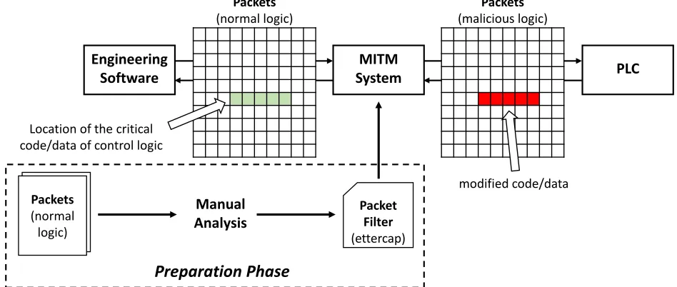
Figure 2.1: Infection hiding based on a packet filter
Operations (DEO) attacks where an attacker can interfere with the normal cycle of an engineering
operation leading to a loss of situational awareness. The attacker can deceive the engineering
software during attempts to retrieve the ladder logic program from a PLC by manipulating the
ladder logic on the PLC such that the software is unable to process it while the PLC continues
to successfully execute it. This attack vector can provide sufficient cover for the attacker’s actual
scenario to play out while the owner tries to understand the problem and reestablish positive
operational control. DEO attacks [16], also uses Ettercap, which has limited support of writing
comprehensive filters to cover complex control logic such as removing a series of malicious rungs in
a ladder logic in network packets (refer to Figure 2.1). On the other hand, CLIK uses virtual PLC
to engage an engineering software without crashing it.
Our decompiler Eupheusis the first developed for the Instruction List defined in IEC 61131-3 to
transform the binary into its corresponding IL source code for Schneider Electric Modicon M221
and SoMachine-Basic engineering software. We further utilize rule-based approach to define criteria
for automated malicious modification of the source code, and then compile the code to transform it
into a binary that can run on the PLC. Then, the binary is transferred to the PLC to compromise
the control logic. We present 3 different attack scenarios, to show that it is flexible enough to allow
different types of attacks, since it can be configured to conjecture semantics of variables in control
Chapter 3
Control Logic Infection Attack
(CLIK)
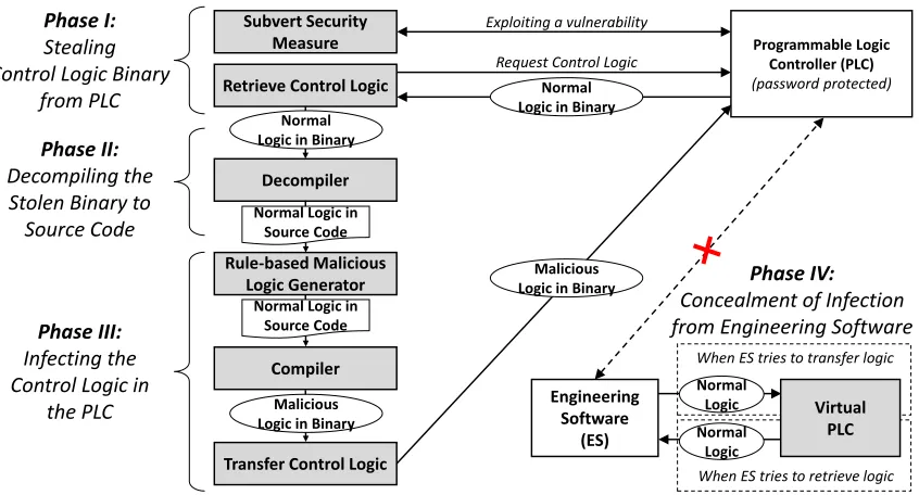
Figure 3.1 shows a high-level overview of CLIK, the proposed control logic infection attack
com-prising of four phases: 1) Stealing the original control logic from a target PLC, 2) decompiling the
stolen low-level (binary) representation of the control logic to its high-level source code, 3) infecting
the source code via rule-based automated approach, followed by compiling the code to a binary
representation (that can run on the PLC) and then, transferring the binary back to the PLC to
infect the control logic, and finally 4) concealing the infected logic in the compromised PLC from
an engineering software at the control center using a virtual PLC.
3.1
Phase I: Stealing the Original Control Logic from a Target
PLC
The first phase involves gaining access to the control logic in a target PLC and retrieves the logic remotely over the network.
Subverting Security Measure This phase includes compromising any security measures that
are supposed to protect a PLC from remote cyber attacks such as theft of control logic. The
security measures include integrity protection of PLC firmware, configuration and control logic,
access control and firewall to segregate PLC based on the access medium (such as the physical interface and communication protocol) and white-listing of IP addresses, and authentication(such as password) to restrict remote read/write access to PLC.
In Section 4.1, we will demonstrate an attack case of subverting the password authentication
Programmable Logic Controller (PLC) (password protected)
Subvert Security Measure
Exploiting a vulnerability
Retrieve Control Logic
Request Control Logic
Decompiler
Normal Logic in Source Code
Rule-based Malicious Logic Generator
Compiler
Transfer Control Logic
Phase I: Stealing Control Logic Binary
from PLC
Phase II: Decompiling the Stolen Binary to
Source Code
Phase III: Infecting the Control Logic in
the PLC EngineeringSoftware
(ES) Normal Logic Normal Logic Virtual PLC
When ES tries to transfer logic
When ES tries to retrieve logic Phase IV: Concealment of Infection from Engineering Software Normal
Logic in Binary Normal
Logic in Binary
Normal Logic in Source Code
Malicious Logic in Binary
Malicious Logic in Binary
Figure 3.1: High-level overview of CLIK, an automated control logic infection attack
CLIK.
Retrieving Control Logic After security measures are compromised,CLIKretrieves the control
logic from the PLC. It communicates with the PLC using the protocol supported by the PLC and
then, requests the control logic. A control logic is typically divided into three parts: configuration
(metadata) blocks, code blocks, and data blocks. Configuration blocks have the mapping addresses
and sizes of other blocks. A code block is the machine code, which executes in PLCs. Data blocks
contain values of variables used by a code block such as input, output, timer, and counter. In
most cases, mapping addresses and sizes of code and data blocks vary, thereforeCLIKfirst retrieves
and parses the configuration blocks to get valid mapping addresses and sizes of other blocks.
3.2
Phase II: Decompiling the Stolen Binary to Source Code
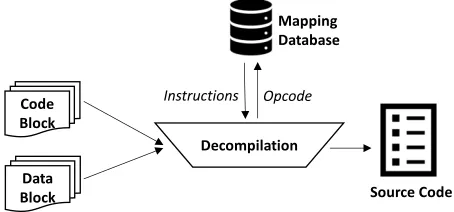
The stolen control logic is in low-level (binary) format. The second phase decompiles the binary into its respective source code for automating the infection phase. The source code is written in
one of the five high-level languages defined in IEC 61131-3 i.e., Instruction List, Ladder Logic,
Sequential Function Charts, Function Block Diagram, and Structured Text. Figure 3.2 illustrates
Code Block
Decompilation
Source Code Opcode
Instructions
Data Block
Mapping Database
Figure 3.2: Decompilation of the Control Logic
opcode to instruction mapping for decompilation. Furthermore, CLIK takes into account the data
block to obtain additional configuration parameters for the instructions. For instance, the timer
instruction has the parameters of preset, time base and the type of timer (Timer On - TON, Timer
Off - TOF, Pulse Timer - TP) in data block.
The decompiler maps each opcode in code block to the database to get the corresponding high
level representation of the instruction inInstruction List.
3.3
Phase III: Infecting the Control Logic via Rule-based
Ap-proach
The third phase is the infection of the control logic that makes rule-based malicious modifications in the (decompiled) source code of the control logic, and then, compiles the modified infected code
to a binary that can run on the PLC. Lastly, it transfers the binary to the PLC.
Rule-based Malicious Logic Generator CLIK employs a rule-based approach to serve two
purposes: 1) identifying a target control logic and then, 2) infecting it automatically.
Toidentify a target control logic,CLIK leverages the semantics of the (decompiled) source code and estimated range of critical variables of a target physical process. In many cases, the source
code contains sufficient semantics of the underlying physical process to generate rules. CLIK for
instance, can look for special instructions in the decompiled code to infer meaning of specific
variables such as set-points. These instructions include PID instructions of Allen-Bradley RSLogix
500, and drive blocks of Schneider Electric SoMachine-Basic. Furthermore, CLIK can look for the
similar to Stuxnet,CLIK can observe the data that range between 807 Hz and 1,210 Hz to identify
variable frequency drives of centrifuges.
To infect the identified control logic, CLIK utilizes preconfigured infection rules including the following: replacing input or output bits with memory bits (to disturb normal update on output
pins), replacing operators in equations, modifying set-points, modifying control flow determinants
(to influence a decision at a conditional branch of control logic), insert/delete instructions/rungs,
etc. For example, similar to Stuxnet, an infection rule can be configured to insert a new rung that
manipulates the set-point of motor speed periodically from 1,410 Hz to 2 Hz to 1,064 Hz leading
to sabotage the centrifuges controlled by the target PLC.
In this phase, we use the resultant decompiled code from network and modify the Instruction
List as a string array and replace or add new rungs and instructions based on the rules and the
type of attack selected.
We present four heuristic rules that can be implemented while changing the Instruction List:
rule 1) replacing input or output bits with memory bits, rule 2) modifying analog control flow
determinant, rule 3) modifying set-points, and rule 4) replacing operators.
The rule 1 can be generally applied for modifying digital values in control logic. By disabling
input and output bits of a control logic, it performs a denial-of-service attack in effect. On the
other hand, rule 2, 3, and 4 focus on modifying analog values in control logic. By examining
analog values, CLIK could be configured to find a target variable in control logic to conduct more
sophisticated modification. If attackers have some estimated range of the target variable,CLIKcan
try to find the target variable based on the estimated value range. A target value estimation can
be done in two ways: observation and general feature.
If the attacker is able to observe the features of the target physical process, for example, the
time period of a traffic light system, that information can be used to configure the malicious logic
generator to find a specific timer preset. Otherwise, the target physical system could have some
general feature. For example, a centrifuge for enriching Uranium-235 is required to spin at 50,000∼
70,000 rpm. Therefore, attackers who want to sabotage a nuclear facility can use this information
to configure the malicious logic generator to find and modify the specific variable related to the
Infection rule 1) Replacing input or output bits with memory bits The infection may
make the PLC unresponsive by replacing memory bits with input or output instructions. This
approach mainly focuses on the digital values in control logic, which can only result into a static
attack with same or similar kind of results when a new rung is appended to the original control
logic.
Infection rule 2) Modifying analog control flow determinant We define that a variableX
is a control flow determinant ifX influences a decision at a conditional branch of control logic. For example, analog control flow determinants include variables of function blocks such as timer preset
and counter preset. The modification is done by following steps: 1) finds all analog control flow
determinants except input/output variables in control logic, 2) if there is configured range of target
variables, finds matching variables among the control flow determinants and modifies them with
configured values, 3) if there is no configured value or fails to find the matching variable, randomly
selects an analog control flow determinant and modifies it with a random value.
Infection rule 3) Modifying set-points A set-point is a desired value for a process value
of systems like a motor frequency of a gas centrifuge. In most of control logic program, a
set-point of underlying physical process is represented using special function blocks or instructions
provided by an engineering software. For example, Schneider Electric SoMachine-Basic provides
drive block which allow drive devices to be controlled by a PLC. Allen-Bradley’s RSLoigx 500
supports proportional integral derivative instructions which control a process variable to be at a
desired set-point using a closed process loop. The modification is done by following steps: 1) finds
those function blocks or instructions which contain a set-points, 2) if there is configured range of
target variables, finds matching variables among the set-points and modifies them with configured
values, 3) if there is no configured target value or fails to find the matching variable, randomly
selects a set-point and modifies it with a random value.
Infection rule 4) Replacing operators in operational blocks Changing the operational
block equation can change the flow of the entire control logic. This modification can be accomplished
by replacing the operators with an opposite operator (like:= can be replaced with<>) which makes
Compiler After the decompiled code block is infected, it is compiled to a binary that can run
on the target PLC. The compiler uses the same database that the decompiler used for conversion
but the other way around. It searches for the instruction opcode for a high level instruction in the
database and replaces the former with the latter.
Transfer of the Control Logic to the PLC The infected control logic is transferred to the
target PLC using the write-requests of the PLC protocol. The modified (infected) control logic
blocks should be mapped to the address of the original blocks to ensure the stable transition of the
PLC to the infected logic.
If the target PLC accepts the write requests of control logic blocks at a specific state of the
protocol implementation, it needs to transit to the valid state before sending write requests. In
addition, if the PLC requires a checksum for control logic, the checksum for the infected control
logic should be calculated.
3.4
Phase IV: Concealing the Malicious PLC Control Logic from
Engineering Software
When the control logic in a target PLC is infected, CLIK hides the infection from the engineering
software to sustain the operation of the infected logic. Existing approaches i.e., Stuxnet [9] and DEO
attacks [16] intercept and modify the packets between the engineering software and PLC to hide the
infection. Stuxnet [9] intercepts control logic packets by replacings7otbxdx.dllofSIMATIC STEP
7 engineering software that handles communication with the PLC and then, masks the infection.
Furthermore, DEO attacks [16] utilize a packet filter of Ettercap [2] and ARP poisoning to intercept
the packets and then, removes the malicious changes in the control logic before forwarding them to
the engineering software.
The current approaches hide the infected control logic successfully. However, they have several
limitations. Stuxnet compromises the integrity of a dynamic link library, which demands advanced
attack capabilities to deceive integrity checking services. DEO attacks [16], on the other hand,
uses Ettercap, which has limited support of writing comprehensive filters to cover complex control
Figure2.1). Also, it leaves several duplicate packets in the network trace due to packet forwarding,
which a network operator can quickly notice by using network monitoring tools such as Wireshark.
Moreover, since the packet filter is generated based on one specific normal control logic, it only
works for that control logic. If the engineering software downloads other control logic to the target
PLC, their packet filter could not correctly locate the critical parts of the control logic.
Virtual PLC We present a new infection hiding method based on a virtual PLC that overcomes
the limitations of the existing approaches. The goal of the virtual PLC is to achieve
stealthi-ness by avoiding significant perturbation in the environment including installing malicious DLL or
generating duplicate traffic.
The virtual PLC utilizes the captured network traffic of the original control logic obtained in
phase 1 ofCLIK to engage engineering software. It is a server program that intercepts the request
messages from an engineering software and then, replies with valid response messages using the
captured traffic. In other words, the virtual PLC mimics the behavior of an uninfected real PLC
from engineering software’s viewpoint.
A Systematic Approach of Building a Virtual PLC. Building a virtual PLC requires reverse engi-neering especially when a target PLC uses a proprietary protocol. In this paper, we present a
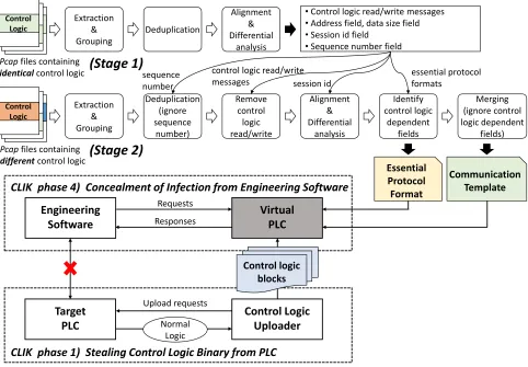
systematic approach to build a virtual PLC. Figure 3.3 presents a systematic approach to build
a virtual PLC. The virtual PLC faces two main challenges. 1) when engineering software sends a
request message, virtual PLC has to identify the corresponding response messages in the captured
traffic, and 2) also adjust the dynamic fields in the response messages whose values vary within
Control Logic Control Logic Virtual PLC Engineering Software Target PLC
CLIK phase 4) Concealment of Infection from Engineering Software
Control Logic
Pcapfiles containing
identicalcontrol logic
•Control logic read/write messages
•Address field, data size field
•Session id field
•Sequence number field
Pcapfiles containing
differentcontrol logic Extraction & Grouping Deduplication (ignore sequence number) Remove control logic read/write Alignment & Differential analysis Identify control logic dependent fields Merging (ignore control logic dependent fields) Control Logic Uploader Extraction & Grouping Deduplication Alignment & Differential analysis Control Logic Control Logic Control Logic Communication Template Essential Protocol Format Control logic blocks
CLIK phase 1) Stealing Control Logic Binary from PLC Upload requests Normal Logic Requests Responses
(Stage 1)
(Stage 2)
sequence numbercontrol logic read/write
messages session id
essential protocol formats
Figure 3.3: A systematic approach to build a virtual PLC
We build virtual PLC based on our insight that the regular traffic (excluding messages containing
control logic in their payload) between engineering software and PLC consist of a manageable
number of different messages that can be represented as a communication template. If a virtual PLC receives a request message, it looks up the template to find a matching request and replies
with the corresponding response message. This approach is black-box that does not require the
complete semantic knowledge of request/response message content, thereby, saving time and effort
for reverse engineering every aspect of the protocol.
Virtual PLC, however, has to take into account some dynamic fields, of which values may change
within a session (e.g., sequence number), between sessions (e.g., session id), and for control logic
(e.g., control logic checksum). Also, since the communication template does not include messages
containing control logic, the virtual PLC has to understand how to generate valid control logic
parts of the protocol format, refer to as essential protocol formats.This section further describes a two-stage process of deriving acommunication templatefrom network-traffic-captures and building an essential protocol format.
Deriving Essential Protocol Format. Stage 1 collects multiple network packet captures of the same control logic and then, processes each packet capture as follows: protocol messages are extracted
and grouped as request and response pair. For instance, some proprietary PLC protocols are
encapsulated by the Modbus/TCP protocol which is a de facto standard communication protocol
widely used in industrial control systems. Since a Modbus request and its corresponding Modbus
response have the same transaction identifier number, encapsulated PLC protocol messages can be
grouped based on the transaction identifier of the Modbus/TCP protocol. After pairing, duplicate
pairs are eliminated. Duplicated messages can exist if there is periodical status check between a
PLC and its engineering software. This process is repeated for all packet captures.
After that, messages in packet-captures are aligned and differences are analyzed. It is possible
to recognize a large chunk of aligned message, since the messages contain same control logic,
which leads to find essential format of a proprietary protocol. We will describe how the alignment
facilitates format recognition for a proprietary PLC protocol in Section 4.6. The essential protocol
format includes dynamic fields such as session id and sequence number, and control logic read/write
message formats.
Building a Communication Template. Stage 2 is similar to stage 1 except that it uses different control logic programs to collect multiple network packet captures. It processes each network
capture by extracting and grouping the messages in request/response pairs, followed by eliminating
duplicate pairs of the messages. If a sequence number field is recognized in stage 1, it is ignored in
the deduplication step. The request and response messages involving control logic read/write are
removed based on the essential protocol format inferred in stage 1.
The remaining messages of the packet captures are aligned, and differences between them are
analyzed. At this step, a session id field is ignored. The aligned message chunks reveal control-logic
dependent fields (since other dynamic fields are ignored in the previous steps) including checksum
During the attack, virtual PLC finds the corresponding messages to a request message using the
communication template and then, adjusts the dynamic fields using the essential protocol format
before sending the messages to engineering software. If the request message is not in the template, it
means it is a control logic read/write request message. The virtual PLC generates a valid response
Chapter 4
Real-world Implementation of
CLIK
We implement CLIK on a real PLC, Schneider Electric Modicon M221, and its vendor-supplied
engineering software (SoMachine-Basic). CLIK is developed in Python and consists of five modules:
1) a password attack module, 2) a control logic upload & download module, 3) IL decompiler &
compiler, 4) a malicious logic generator, and 5) a virtual M221 PLC. Since the M221 PLC uses a
proprietary protocol and the format of the control logic blocks were unknown, we had to do some
reverse engineering. The detailed efforts of our reverse engineering works are not described here
for space reason.
4.1
Subverting PLC Password Protection by Exploiting a
Zero-day Vulnerability
Since the latest version of the M221 PLC is protected by a password authentication mechanism,
an unauthorized user is not allowed to read the control logic of the PLC. For example, one can not
upload the control logic of the M221 PLC without the correct password if the password protection
option is enabled. We have found a zero-day vulnerability in the authentication mechanism and
further develop a proof-of-concept exploit to subvert the password protection. We confirmed that
the latest version of firmware (v1.5.1.0 and v1.6.0.1) and SoMachine-Basic (v1.5 and v1.6) are
impacted by this vulnerability, and reported this to the vendor.
Figure 4.1 describes the authentication process between an M221 PLC and SoMachine-Basic.
First, the engineering software requests a one-byte random mask (mask1) from the PLC. After receiving (mask1), the engineering software sends one-byte random mask (mask2) to PLC along with the masked value of the password hash for authentication. The masked value is computed by
Engineering
Software PLC
1) Request mask1
2) Send mask1
3) Authentication request (mask2, masked_hash)
4) Authentication response
mask1: 1 byte size random value mask2: 1 byte size random value
passwd_hash: SHA256 hash of password masked_hashis calculated as:
for i= 0 tobyte size of passwd_hash– 1 do
masked_hash[i] = passwd_hash[i] ⨁mask1⨁mask2 (masked_hash[i]: ithbyte of masked_hash)
Figure 4.1: Normal password authentication between the Schneider Electric Modicon M221 PLC and SoMachine-Basic engineering software
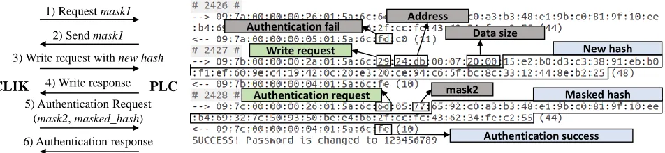
Address Authentication success Data size Masked hash New hash mask2 Write request Authentication request CLIK PLC Authentication fail 1) Request mask1
2) Send mask1
3) Write request with new hash
4) Write response
5) Authentication Request
(mask2, masked_hash)
6) Authentication response
※ 3) ~ 6) are repeated until get authentication success response
Figure 4.2: Password authentication while exploit the vulnerability in the Schneider Electric Mod-icon M221 PLC by theCLIK
initially performed by the engineering software. If both masked-hashes are identical, the PLC
grants access permissions to the engineering software.
The M221 PLC does not allow reading control logic remotely before authentication. However,
writing to the PLC is still allowed, which is an exploitable vulnerability. We demonstrate that an
attacker can reset the password by overwriting the original password hash with its own. However,
the challenge for the attacker is to identify the correct location of the hash code in the PLC to
overwrite.
Figure 4.3 shows the address space layout of the M221 PLC. We find out that the password
hash is always preceded by a variable sizezipfile containing metadata of the control logic. We also
discover that the zip file is mapped at the fixed address (0xd000). Furthermore, the code block of
the control logic, which is a machine code of Renesas RX630 microcontroller [14], is always mapped
at an arbitrary location starting from 0xe000, referred to as random gap. Thus, we compute that there is anunused areabetween the end of the password hash and the address 0xe000.
A zip file (metadata)
Password hash
Unused area
Random gap
Code block (RX630 machine code)
…
… 0xd000
0xe000 N(bytes)
Figure 4.3: Address space of the M221 PLC
valid password, the attacker still can write values to the PLC. Therefore, if an attacker knows the
address where the authentication key (e.g. password hash) is stored, the attacker can pass the
authentication by overwriting the original authentication key with attacker’s key.
The address is represented by a two-byte field in read/write messages of the M221 PLC protocol.
The M221 PLC uses a password hash as authentication key, and the password hash is always
preceded by a variable size zip file containing metadata of the control logic. We also found out that
the zip file is mapped at fix address (0xd000) and the code block of the control logic, which is a
machine code of Renesas RX630 microcontroller [14], is always mapped at arbitrary address above
0xe000. Therefore, there is unused area between the end of the password hash and the address
0xe000.
To identify the correct location of the hash code to overwrite with new password hash, the
attacker can compute negative or positive offsets from a known reference point to password hash.
Unfortunately, the offsets are not consistent because of the following reasons. To compute the
positive offset, we know the starting address of the zip file. However, the size of the file varies and cannot be found during the attack. To compute thenegativeoffset, we know that the code block of control logic starts from any random location after0xe000. However, the random location is not
apparent making the offset value unpredictable.
The other approach is to fill the memory between the zip file and 0xe000with the attacker’s
password hash. However, this approach is not reliable. It can start overwriting the memory from
0xe000to password hash, but cannot precisely determine the end of the zip file since the file size
varies, which may cause exceeding the hash location and overwriting the zip file contents.
Furthermore, the size of the SHA-256 hash is 32 (0x20) bytes. The original hash must be located
hash.
Figure 4.2 shows the overview of the password authentication while exploit the vulnerability.
Algorithm 1describes the exploit method that takes advantage of the vulnerability and resets the
original password of the M221 PLC with an attacker’s password. It assumes that the password hash
is located anywhere starting from0xe000to a negative offset. Since the size of the SHA-256 hash is
32 bytes (0x20), it first overwrites the address 0xdfe0∼0xe000with the new password hash (line
10 in Algorithm 1) and then, sends an authentication request to the target PLC using mask2 and
maskedHash (line 11). If the authentication fails, it iteratively performs the same steps. However, every iteration overwrites the hash value to the memory location, which is one-byte negative offset
from the last address. For instance, the next address after the first failed authentication is0xdfdf
∼0xdfff. At some point, an iteration overwrites the original hash code completely with the correct
alignment, which resets the password and authenticates successfully.
Since the size of the SHA-256 hash is 32 (0x20) bytes, it first overwrites the address0xdfe0∼
0xe000with the new password hash (line 10). Then, send an authentication request to the target
PLC using mask2 and maskedHash (line 11). If the authentication fails it overwrites the next address0xdfdf∼0xdfffand send an authentication request again. In this manner, it iteratively
overwrites the address space until an authentication success message is received.
It first calculate newHash (line 1) and get mask1 from the PLC (line 2). Then, mask2 is set with an arbitrary value (line 3). maskedHash is calculated fromnewHash,mask1, andmask2 (line 6-8). Then it iteratively overwrite targetAddr with the maskedHash as follow (line 9-14). When the size of the password hash is 32 (0x20) bytes, an attacker first overwrite the address0xdfe0∼
0xe000with the attacker’s password hash, then send an authentication request to the target PLC
using the attacker’s password hash. If the authentication fails the attacker overwrite the address
(0xdfe0 - 1) ∼ (0xe000- 1) and send an authentication request again. In this way, the attacker
iteratively overwrite the address (0xdfe0 - 2) ∼ (0xe000 - 2), (0xdfe0 - 3) ∼ (0xe000 - 3), ...,
Algorithm 1 Pseudocode for password reset attack
Input: New password
Result: Reset password with the new password
1: newHash←sha-256 hash of the new password 2: mask1←Requestmask1 from the PLC
3: mask2←A random number between 0 and 255 4: targetAddr←0xdfe0
5: hashSize←32
6: fori= 0 to hashSize−1 do
7: maskedHash[i]←newHash[i]⊕mask1⊕mask2
8: end for
9: whileres=F alse do
10: Send a write request (addr:targetAddr, size:hashSize, data:newHash) to PLC 11: Send an authentication request (mask2,maskedHash) to PLC
12: res←Received result of the authentication request 13: targetAddr←targetAddr−1
14: end while
4.2
Control Logic Uploader & Downloader
TheUploaderandDownloaderretrieves the control logic from and transfer it to a PLC respectively. In M221 PLC, the control logic consists of six blocks. We refer to them as conf1, conf2, code,
data1, data2, and zipHash since the protocol is proprietary and its specification is not publicly
available. The conf1 and conf2 blocks have information of other blocks. The code block is
the compiled version of control logic in RX630 machine code. The zipHash block consists of a
zip file (metadata of control logic) and password hash (if password protection option is enabled).
The data1 block contains the values of the variables used in control logic. The data2 block has
information about the data1block.
The Uploader reads all six blocks of the control logic from the M221 PLC. It first obtains the address and size of each block and then, sends read messages to the PLC to retrieve the entire logic.
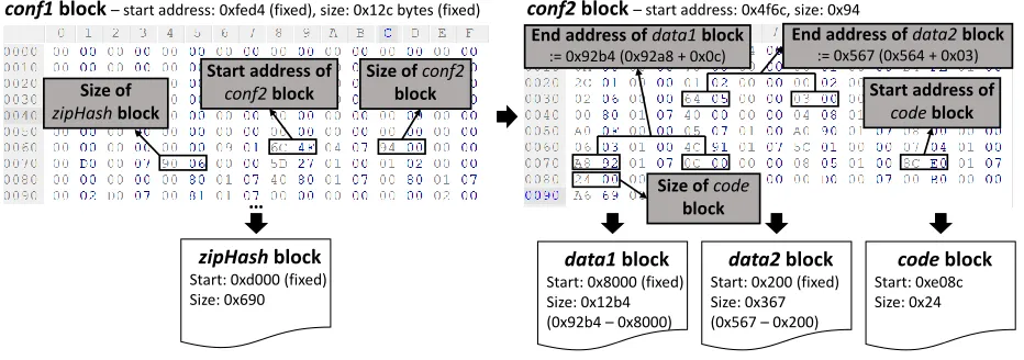
Figure 4.4 illustrates the process of getting the address and size of the blocks. We find that the
conf1block is always mapped at a fixed address (0xfed4) and has the fixed size of 300 bytes. The
conf1 block is then used to derive the size of the zipHash block, and the size and address of the
conf2 block. The conf2 block is retrieved from the PLC and then, used to derive the size of the
data1, anddata2blocks, and the address and size of thecodeblock. After obtaining the addresses
conf1block –start address: 0xfed4 (fixed), size: 0x12c bytes (fixed) conf2block –start address: 0x4f6c, size: 0x94
zipHashblock Start: 0xd000 (fixed) Size: 0x690
Start address of
conf2block
Size of conf2
block Size of
zipHashblock
End address of data2 block := 0x567 (0x564 + 0x03)
Start address of
codeblock
Size of code
block End address of data1 block
:= 0x92b4 (0x92a8 + 0x0c)
data1block Start: 0x8000 (fixed) Size: 0x12b4 (0x92b4 –0x8000)
data2block Start: 0x200 (fixed) Size: 0x367 (0x567 –0x200)
codeblock Start: 0xe08c Size: 0x24
…
Figure 4.4: Start address and size of M221 control logic blocks
The Downloadersends write-requests to the PLC with the corresponding addresses and size of the control-logic blocks. During the CLIK attack, the Malicious Logic Generator modifies either data1 or code block, or both. The Downloader sends write-requests containing modified-blocks with their original addresses and current sizes that may be different from original sizes after
mod-ifications.
4.3
IL Decompiler & Compiler
SoMachine-Basic (an engineering software) supports two programming languages, ladder logic,
and IL. The ladder logic consists of rungs and each rung has instructions. The SoMachine can
interchange the instructions between the two languages. When SoMachine compiles a control logic
program, it converts the program into RX630 assembly code.
IL Decompiler We implement the decompilerEupheusthat takes the RX630 code as input and
decompiles it into IL source code. We choose IL over ladder logic because IL is text-based and easier
to manipulate. Ladder logic, on the other hand, is a graphical language where each instruction is
represented as a graphical symbol and the instructions are grouped into rungs.
The decompilerEupheushas two main components: First, thedatabasefor mapping the opcodes to their corresponding IL instructions (refer to Figure4.7). Currently, the database consists of 4079
mappings for 21 types of different instructions including input and output, relative branch, control
blocks in the M221 control logic and the mapping database to process the code block. In the first
step of decomilation mapper divides the control logic into individual rungs, using two criteria, a
rung can be separated when an output instruction is followed by an input instruction or if the rung
has a control block instruction likeTimerorControllerit ends with theEND BLKinstruction which
is considered as a delimiter in the database. when the rungs are separated and stored into an array,
the mapper proceeds to the next step: replacing the binary with appropriate instructions. The
mapper finds the RX630 instructions of the code block in the database of opcodes to obtain their corresponding IL instructions. We notice that RX630 program maintains the essential constructs
of both languages, IL and ladder logic to facilitate the decompilation by SoMachine. The mapper
therefore, first identifies the rungs in RX630 program and then, processes each rung to identify IL
instructions.
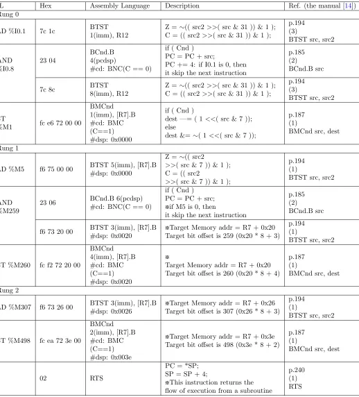
The Table4.1shows an example of RX630 control logic that is mapped to IL instructions. The
rungs are separated when an output instruction opcode is preceded by the instruction opcode of an
input or a control block instruction such asTimerorCounter. In the latter case, the rung ends with
END BLKinstruction denoted as7F 1A 11in RX630 control logic, The Figure4.8shows an example
of control logic that is using timer. After the rungs are separated, Eupheus decompiles each rung
at a time by identifying the instructions in the database and replacing the RX630 instruction with
equivalent IL instruction. The bitwise AND and OR are denoted in control logic as 0x23 and 0x22
respectively, followed by the byte that indicates the total number of bytes of the next instruction.
For example, 7C 0C 23 04 7C 1C represents that the two instructions 7C 0C and 7C 1C are in
series connection and the 04shows that the next instruction has two bytes.
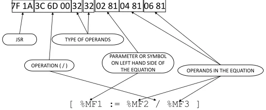
The control logic sometimes contain Operational Blocks, equations using memory floats or
memory words, which are used as control flow determinants for the physical process. In such cases
binary uses the opcode7F 1Awhich means Jump to Sub-Routine in RX630. The mapper database
is not enough to decompile in this situation. So we implemented a separate program to decompile
the operation block equations. There is a specific code for each arithmetic operation in the binary.
we stored each operation so that when we come across the operation code, the operational block
decompilation program can be used. The binary has a specific structure for the equation as shown
in the Figure 4.5.
7F 1A 3C 6D 00 32 32 02 81 04 81 06 81
[ %MF1 := %MF2 / %MF3 ]
JSR
OPERATION ( / )
TYPE OF OPERANDS
PARAMETER OR SYMBOL ON LEFT HAND SIDE OF
THE EQUATION OPERANDS IN THE EQUATION
Figure 4.5: Simple Operation Block
with temp variables. The Figure 4.6 shows an example of complex equation breakdown in the
control logic binary and the usage of TEMP variable to connect each simple equation and form the
resultant complex equation. In the example given below the operand type 32 means the variable
and the type29means constant. Each operation have different code in the binary with one to one
connection.
OPERATION OPERAND TYPES
USINGTEMP
VARIABLE
Figure 4.6: Complex Operation Block
The mapper program finds the operation block binary and sends it to the Operational Block
Decompiler. the programs checks the binary and determines the complexity of the equation. The
simple equation can be decompiled by getting the operator from the database and decompiling the
constant and the variable. However when the equation is complicated like in the example given
in Figure4.6 we have to determine the temp variable initialization, utilization and the assignment
of the TEMP variable. in the first step we decompile individual equations with the temp variable.
Next we replace the temp variable with the equation assigned to it to form the final equation. The
tricky part is as given in the figure if the temp variable is reassigned, that is if the temp variable
equations step by step.
Mapping Database The database maintains the opcodes of RX630 instructions and their
cor-responding IL instructions along with the category of the instruction such as inputs, outputs and
relative branch instructions (AND,OR, etc.). The logic also has timer specifications such as 23 00
indicates that the timer type is TONand the preset is 1.00 second.
includes Instructions table with the opcodes with their corresponding instructions and the
category of the instruction ( inputs, outputs and relative branch instructions like AND and OR).
MetaData table includes timer specifications like 23 00 indicates that the timer type is TON and
the preset is1s
The database stores each instruction opcode and the equivalent instruction in a table called
Instructions. This table includes Input instructions, output instructions, relative branch
in-structions and block inin-structions which are constructed based on RX630 microcontroller assembly
language.
However, The conditional blocks or the operational blocks in the Instruction list may not be
completely mapped to the assembly code of RX630, as they use Jump to Sub Routine(7f 1a 10)
to represent the Block instruction and after that the Hex code represents each input and output
differently even then we were able to see some pattern to map the Instruction list and the code from
network packet. Also the Operational blocks that use Memory words/floats are also represented
with control logic that starts with (7f 1a) but the next few bytes of code is not as explained in the
microcontroller assembly language.
The database includes Instructions table with the opcodes with their corresponding instructions
and the category of the instruction ( inputs, outputs and relative branch instructions likeAND and
OR). MetaData table includes timer specifications like 23 00 indicates that the timer type is TON
and the preset is 1s
Mapping Program The mapper program processes the M221 control logic by first dividing it
into separate rungs. Each rung may have opcodes of input, output and conditional block
instruc-tions that are searched in the database to find their equivalent IL instrucinstruc-tions.
of control logic.
IL Compiler The compiler is the reverse process of the decompilerEupheus, which uses the same
database to get the equivalent RX630 opcode of every instruction in Instruction List.
Original Control Logic (Engineering software) Decompiled Control Logic (Eupheus)
Figure 4.7: Mapping RX630 Opcodes with IL Instructions
4.4
Mapping RX630 Opcodes with IL Instructions
CLIK employs rule-based approach to inject malicious logic in the decompiled IL code of RX630
control logic automatically. The decompilation ensures that CLIK understands the RX630 control
logic correctly since the opcode of each instruction is of different size; a longer opcode of an
instruction may contain one or more smaller instruction opcodes. Furthermore, the original control
logic is written in high-level language such as IL. Thus, it is easier to identify malicious logic for
an IL control logic code than RX630 machine code.
4.5
Malicious Logic Generator
We used the decompiled Instruction List to modify or insert rungs to perform malicious activities
when the code is executed by the PLC. The reason behind this is the opcode of each instruction is in
different length, the longer instruction opcode the more chances that it might contain one or more
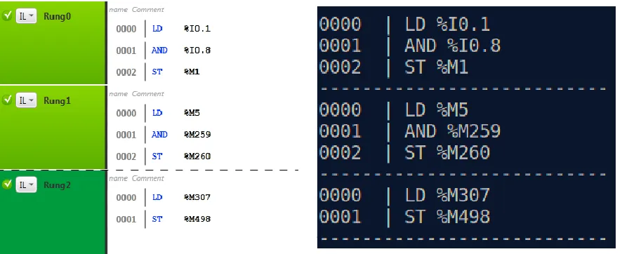
Table 4.1: Instruction List representation and corresponding machine code description
IL Hex Assembly Language Description Ref. (the manual [14]) Rung 0
LD %I0.1 7c 1c BTST 1(imm), R12
Z =∼(( src2 >>( src & 31 )) & 1 ); C = (( src2>>( src & 31 )) & 1 );
p.194 (3)
BTST src, src2
AND %I0.8
23 04
BCnd.B 4(pcdsp)
#cd: BNC(C == 0)
if ( Cnd ) PC = PC + src;
PC += 4: if I0.1 is 0, then it skip the next instruction
p.185 (2)
BCnd.B src
7c 8c BTST 8(imm), R12
Z =∼(( src2 >>( src & 31 )) & 1 ); C = (( src2>>( src & 31 )) & 1 );
p.194 (3)
BTST src, src2
ST
%M1 fc e6 72 00 00
BMCnd 1(imm), [R7].B #cd: BMC (C==1) #dsp: 0x0000
if ( Cnd )
dest —= ( 1<<( src & 7 )); else
dest &=∼( 1 <<( src & 7 ));
p.187 (1)
BMCnd src, dest
Rung 1
LD %M5 f6 75 00 00 BTST 5(imm), [R7].B #dsp: 0x0000
Z =∼(( src2
>>( src & 7 )) & 1 ); C = (( src2
>>( src & 7 )) & 1 );
p.194 (1)
BTST src, src2
AND %M259
23 06 BCnd.B 6(pcdsp) #cd: BNC(C == 0)
if ( Cnd ) PC = PC + src; ※if M5 is 0, then
it skip the next instruction
p.185 (2)
BCnd.B src
f6 73 20 00 BTST 3(imm), [R7].B #dsp: 0x0020
※Target Memory addr = R7 + 0x20 Target bit offset is 259 (0x20 * 8 + 3)
p.194 (1)
BTST src, src2
ST %M260 fc f2 72 20 00
BMCnd 4(imm), [R7].B #cd: BMC (C==1) #dsp: 0x0020 ※
Target Memory addr = R7 + 0x20 Target bit offset is 260 (0x20 * 8 + 4)
p.187 (1)
BMCnd src, dest
Rung 2
LD %M307 f6 73 26 00 BTST 3(imm), [R7].B #dsp: 0x0026
※Target Memory addr = R7 + 0x26 Target bit offset is 307 (0x26 * 8 + 3)
p.194 (1)
BTST src, src2
ST %M498 fc ea 72 3e 00
BMCnd 2(imm), [R7].B #cd: BMC (C==1) #dsp: 0x003e
※Target Memory addr = R7 + 0x3e Target bit offset is 498 (0x3e * 8 + 2)
p.187 (1)
BMCnd src, dest
02 RTS
PC = *SP; SP = SP + 4;
※This instruction returns the flow of execution from a subroutine
p.240 (1) RTS
Figure4.9shows some examples of such cases, where inserting or changing the code is complicated.
Block start (BLK) XIO(LD %I0.0) Series Connection (AND) XIC (N %M2)
OTE (ST %M0)
End of control logic Indicating the end of rung
which contains the Timer (END_BLK) Timer ID 0 ( TM0)
Timer Input (IN)
Out Block (OUT_BLK) Timer Output Q for
Timer TM0 (LD Q)
End of first rung
Start of next rung
Figure 4.8: Mapping opcode with Instructions
Rules We define five heuristic rules to modify the IL code; more rules can be included to improve
the malicious logic generator: Rule-1: If input/output bits are found then, replace them with memory bits. Rule-2: If a configured range of target variable matched then, modify its determinant.
Rule-3: If a set-point is less than a ¡certain value¿ then, modify the set-point. Rule-4: If an operational block has an equation then, replace an operator in the equation. For instance, the
operator := can be replaced with <>. Rule-5: Insert a new rung at the end of the logic with an energizer output of a target actuator to override the output with the attacker’s desired value.
The rule 1 can be generally applied for modifying digital values in control logic. By disabling
input and output bits of a control logic, it performs a denial-of-service attack in effect. On the
other hand, rule 2, 3, and 4 focus on modifying analog values in control logic. By examining
analog values, CLIK could be configured to find a target variable in control logic to conduct more
sophisticated modification. If attackers have some estimated range of the target variable,CLIKcan
try to find the target variable based on the estimated value range. A target value estimation can
be done in two ways: observation and general feature.
First, attackers might be able to observe the features of the target physical process. For example,
attackers can observe time period of a traffic light system and use that information to configure
the malicious logic generator to find a specific timer preset. Otherwise, the target physical system
f6 73 00 00 LD %M3 fc f6 73 00 00 STN %M5
ef ce 7e 0e 7c 0e N %I0.0 ef ce 7e 0e 7c 1e N %I0.1
ce 7e 00 00 7e 0e 7c 0e N %M0 ce 7e 00 00 7e 0e 7c 1e N %M1
ce 7e 01 00 7e 0e 7c 0e N %M8 ce 7e 01 00 7e 0e 7c 1e N %M9
ce 7e 02 00 7e 0e 7c 0e N %M16 ce 7e 02 00 7e 0e 7c 1e N %M17
ce 7e 03 00 7e 0e 7c 0e N %M24 ce 7e 03 00 7e 0e 7c 1e N %M25
…. ….
ce 7e 3f 00 7e 0e 7c 0e N %M504 ce 7e 3f 00 7e 0e 7c 1e N %M505
7f 1a 11 Out Block 7f 1a 11 End Block
Figure 4.9: Similar Opcode Examples
spin at 50,000∼70,000 rpm. Therefore, attackers who want to sabotage a nuclear facility can use
this information to configure the malicious logic generator to find and modify the specific variable
related to the target variable-frequency drive of a gas centrifuge.
Infection rule 1) Replacing input or output bits with memory bits The infection may
make the PLC unresponsive by replacing memory bits with input or output instructions. This
approach mainly focuses on the digital values in control logic, which can only result into a static
attack with same or similar kind of results when a new rung is appended to the original control
logic.
Infection rule 2) Modifying analog control flow determinant We define that a variableX
is a control flow determinant ifX influences a decision at a conditional branch of control logic. For example, analog control flow determinants include variables of function blocks such as timer preset
and counter preset. The modification is done by following steps: 1) finds all analog control flow
determinants except input/output variables in control logic, 2) if there is configured range of target
variables, finds matching variables among the control flow determinants and modifies them with