Open Access
Research
Keratometry device for surgical support
Liliane Ventura*
1, Jean-Jacques De Groote
1, Paula Saia
1and Sidney J Faria e
Sousa
2Address: 1Dept of Elect Engineering USP (Ophthalmic Instrumentation Division), Av Trabalhador sao-carlense 400, S Carlos, SP 13566-590, Brasil and 2Dept of Ophthalmology USP, Av Bandeirantes 3900, Rib Preto, SP 14100-900, Brasil
Email: Liliane Ventura* - [email protected]; Jean-Jacques De Groote - [email protected]; Paula Saia - [email protected]; Sidney J Faria e Sousa - [email protected]
* Corresponding author
Abstract
Background: High astigmatisms are usually induced during corneal suturing subsequent to tissue transplantation or any other surgery which involves corneal suturing. One of the reasons is that the procedure is intimately dependent on the surgeon's skill for suturing identical stitches. In order to evaluate the influence of the irregularity on suturing for the residual astigmatism, a prototype for ophthalmic surgical support has been developed. The final intention of this prototype is to be an evaluation tool for guided suture and as an outcome diminish the postoperative astigmatism.
Methods: The system consists of hand held ring with 36 infrared LEDs, that is to be projected onto the lachrymal film of the cornea. The image is reflected back through the optics of the ocular microscope and its distortion from the original circular shape is evaluated by developed software. It provides keratometric and circularity measurements during surgery in order to guide the surgeon for uniformity in suturing.
Results: The system is able to provide up to 23D of astigmatism (32D - 55D range) and is ± 0.25D accurate. It has been tested in 14 volunteer patients intraoperative and has been compared to a commercial keratometer Nidek Oculus Hand-held corneal topographer. The correlation factors are 0.92 for the astigmatism and 0.97 for the associated axis.
Conclusion: The system is potentially efficient for guiding the surgeon on uniformity of suturing, presenting preliminary data indicating an important decrease on the residual astigmatism, from an average of 8D - for patients not submitted to the prototype guidance - to 1.4D - for patients who have actually been submitted to the prototype guidance - after the first 24 hours post-surgery and in the subsequent weeks. It also indicates that the surgeon should achieve circularity greater or equal to 98% in order to avoid postoperative astigmatisms over 1D.
Trial Registration: Trial registration number: CAAE - 0212.0.004.000-09.
Background
One of the significant provoking factors of corneal astig-matism during the surgical procedure is the irregularity in suturing the tissue. Sutures are manually performed on
the cornea and systems for monitoring the circularity of the suturing [1-4] are not often used. Most of them are just qualitative.
Published: 8 December 2009
BioMedical Engineering OnLine 2009, 8:37 doi:10.1186/1475-925X-8-37
Received: 11 May 2009 Accepted: 8 December 2009 This article is available from: http://www.biomedical-engineering-online.com/content/8/1/37
© 2009 Ventura et al; licensee BioMed Central Ltd.
Refractors [5] are used to measure the astigmatism of the eye, which is a refractive error of the ocular medium. keratometers are instruments used to measure objectively the radii of corneal curvature along the two main meridi-ans of the cornea. They provide the mean corneal astigma-tism. Most of the current keratometers perform the measurements on patients' eyes at the sitting up position, i.e. in a vertical position. Only a few commercially availa-ble models are apt to perform keratometry on a patient in a lying down position, i.e., horizontally positioned. Therefore, some surgeons consider hand held surgical keratometers unreliable [6] and it may be due to the fact of positioning it, as well as, due to measurements that are performed in horizontal position are, to some extent, dif-ferent from measurements performed in a vertical posi-tion.
The optical principle of keratometers is already well known [7] and some of the current authors have previ-ously developed a keratometer module for slit lamps, which performs keratometry with the patient in the verti-cal position [8-10].
The intention of the present work is to evaluate the post-operative residual astigmatism to understand if a regular suturing is of any benefit for the patient.
Thus, we have developed a system that allows automated keratometry as well as an objective real-time orientation for the surgeon for suturing the corneal tissue as circular as possible, expecting to reduce the residual the post-oper-ative corneal astigmatism. The goal is to develop a proto-type and do preliminary tests on the device and not do a full-blown clinical study to prove its commercial and daily clinical routine availability. It is mostly to check about its influence on guiding suturing as a better result for the postoperative astigmatism.
A brief description of the optical properties of the human cornea that concerns this work will be made as well as the calculus involved for determining the radii of curvature of the cornea will be described.
Optical Properties of the Human Cornea
The human cornea is the optical component, which is the surface with external contact with the light that penetrates the eye; therefore its shape and physical structure are inti-mately related to the quality of vision.
The shape of the cornea is not spherical overall, it is actu-ally ellipsoidal, but the 3 mm central region of the cornea [11,12] - the central optical zone - where keratometry is performed, may be considered as spherical. The adult cor-nea is 11-12 mm wide in the horizontal plane and 9-11 mm in the vertical plane. The circumference of its base has
a diameter of approximately 12.5 mm. It is approximately 500 μm thick at the central portion and up to 700 μm thick at the periphery [12-15].
The corneal radius of curvature is not regular in its entire surface; it is smaller at the centre (higher curvature) and flattens towards the periphery, causing an aspherical sur-face.
The radius of curvature in the central optical zone varies form 7.5 - 8.0 mm (typically 7.8 mm), its refractive index is n = 1.376 and the refractive power of the cornea varies from 40 - 44D (the cornea is responsible for 2/3 of the overall refractive power of the eye).
The cornea is equivalent to a positive lens. However it is a very thin structure and the central part of the cornea may be considered as having parallel faces for keratometry pur-poses [11,12].
The cornea may be considered as a convex mirror, which provides a virtual image of the projected light source struc-ture.
For keratometry purposes just the central optical zone will be analysed, thus the spherical model is sufficient and accurate, but for small radii of curvature, no approxima-tions should be made, as we have learned from the devel-opment and tests of our first keratometry system for slit lamps [8-10].
If an object of size 2R (R is the radius of the circular target) is perfectly focused onto the cornea, the reflection of the object provides a virtual image i, which corresponds to one half of the dimension of the projected target onto the cornea (around 1.5 mm) [9].
The distance between the object and its image d is 0.20 m for the surgical ocular microscope that we have used.
Considering that the light rays coming from R reach the optical axis at small angles, it is possible to say that the focusing distance is one half of the curvature radius of the cornea (r). Therefore, the radius of curvature r (in meters) of the surface to be determined is [9]:
The keratometric results are usually presented as "Refrac-tion Power" (P), given by expression (2) and the unit is expressed in diopters (D).
r Ri R i
= −
−
4 2 210
1
(1)
P nc r
nc (1.3375) is the corneal refractive index of the cornea often used for keratometric purposes [16].
Methods
A target, which is the object projected onto the lachrymal film of the examined cornea, consists of several light spots (LEDs) displayed in a circle. The displacement, the size and deformation of the reflected image of these light spots are analysed providing the keratometry and the circularity of the suture.
The engineering of the system basically consists of a hand-held projection target; a video system for capturing the reflected image of the light spots from the cornea; a soft-ware for image processing and keratometric and circular-ity results.
Hand-held projection target
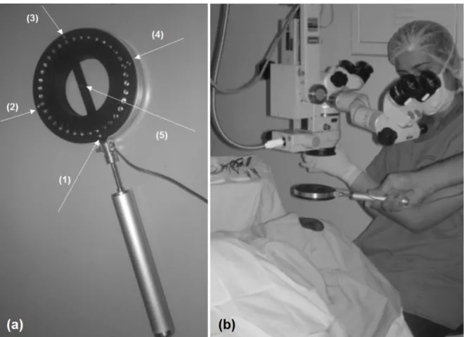
The projection target has 36 infrared LEDs (high intensity - connected in parallel - 5 V and 50 mA) displayed in a perfect circle - ϕ = 53.8 mm -, 5 extra LEDS (one for center alignment of the system and 4 additional ones for angular alignment) - as shown in figure 1a - and which is to be held by the surgeon, as presented in figure 1b.
The target has a simple design that projects the light spots homogeneously in a precise circle of 3 mm of diameter in a standard cornea, i.e., with radius of curvature of 7.895 mm (a stainless steal sphere with precision of ± 0.0025
mm has been used as a standard cornea for calibrating the system). The light target should be held ideally 50 mm away from the cornea.
The handle of the luminous target is connected to a pedal that is placed under the surgical table. As the surgeon presses the left side, it lights up the luminous target; as the right side is pressed, the image is captured and the 5 guid-ing LEDs go off automatically. Alternatively, two push buttons may be placed at the handle for these purposes, but the surgeons who had been testing our system would rather have foot control.
As the target is turned on, it is focused by the surgeon at the examined eye. During the examination, the light from the surgical microscope is turned off.
The image of the target projected onto the patient's cornea is reflected back through the central aperture of the target, straight forward to the objective of the microscope and then through the observation system. A beam-splitter is placed between the magnification system and the eye-pieces of the microscope (70% of the reflected light is deviated to the eyepieces). A regular video optical adapter for surgical microscopes is coupled to the beam-splitter and a CCD camera WATEC 221S is attached to it. Figures 2a and 2b show the images of the target projected onto the calibrating sphere and onto the patient's cornea.
(a) The projection system: Target with 36 LEDS displayed in a perfect circle to be used during a corneal suturing; (b) the target itself
Figure 1
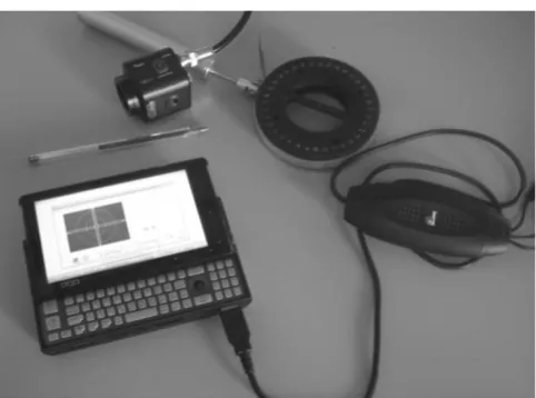
The reflected image is analyzed by the software at a micro computer OQO - model 2 coupled to the CCD camera via a video bus cable (Pinnacle), as shown in figure 3.
While the surgeon is suturing the cornea, the physician should hold the target parallel to the cornea and align it guided by the 5 extra LEDs.
Manual focusing and image capturing processes take around 20-35 s depending on the familiarity of the sur-geon with the prototype.
As the suture is being performed, the surgeon should instil some drops of saline and do the measurement. The image should be focused and the guiding LEDs 1-4 help to avoid tilting. The surgeon presses a pedal connected by the exter-nal cables, shown in figure 1b, that are connected to a micro computer by the USB port, and the image is cap-tured. LEDs 1-5 are OFF at this time and just the remain-ing 36 LEDs are identified for keratometry.
The image is processed and the result is presented in a few milliseconds (typically 130 ms - refer to processing time in the software figure, furthermore).
The circularity of the cornea is presented as well as the keratometry, to avoid flattening or over bending of the cornea.
The developed software
The developed software for supporting corneal suturing consists of 5 fundamental parts: image processing; keratometry measurement; circularity indication; user interface; calibration routine.
Image Processing
The software is based on the information provided by the structure of the projecting target, determining its distor-tion as its image is reflected back from the cornea. The dis-tortions analyzed between the original shape of the projected target and its reflected image contains informa-tion to provide the keratometric data.
Differently from the usual keratometers, the keratometric module for the ocular microscope is not usually operated in an environment free from external disturbances, as room light, for example. Hence, the developed algorithm is capable to avoid these kinds of interferences in the image processing.
Non-uniformity of brightness distribution in the image of the light spots that reach the examined surface results in loss of information in the identification process of the tar-get's shape. The developed algorithm considers this possi-bility, once it provides the keratometric results even if some light spot is missing in this process.
There is a considerable variation of the brightness of the light spots, in the grayscale image. Therefore, a blurring process is used by a matrix 3 × 3 as:
Subsequently, a convolution process is applied, using a circular mask with diameter based on the average diame-ter of the light spots, providing means to identify each LED position in the image.
As the mask is moved along the image, the pixel corre-sponding to the highest intensity is the first to be identi-fied.
The center of mass having a well defined position is iden-tified and its location is saved as (Px[1], Py[1]) Proceeding
1 1 1 1 1 1 1 1 1
⎡
⎣ ⎢ ⎢ ⎢
⎤
⎦ ⎥ ⎥ ⎥
(3)
Target projected onto: (a) a stainless steal sphere; (b) the patient's cornea during surgery
Figure 2
Target projected onto: (a) a stainless steal sphere; (b) the patient's cornea during surgery.
Devices for assisting regular corneal suturing Figure 3
in a recursive way, the lower intensity structures are then identified
As the Ne (LEDs) structures are identified, the positioning of their respective centre of mass (Px [i], Py), (xcm0, ycm0) may be identified, providing the location of the centre of the whole image given as:
Therefore, an interpolated curve is obtained from the position of the centre of mass of the reflected image of the target.
Software for Keratometric Measurements
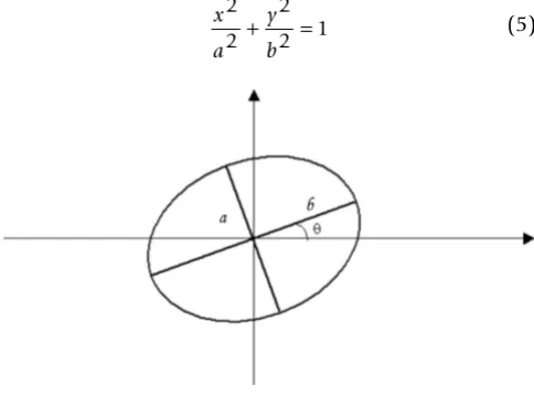
The mathematical fitting expression of the reflected image of the target onto the cornea is an ellipse, with an inclina-tion angle of θ related to the x axis of the coordinate sys-tem, as represented in figure 4. The coordinate system is X, Y and a and b are the minor and major axis of the ellipse, respectively.
The fitting is performed using the interpolated data deter-mined from the image processing.
These data were defined in polar coordinates for the angles Θi = ni, Θ0, where 0° ≤Θi ≤ 360°. In order to guar-antee accuracy of the measurements, the angle was chosen to be Θ0 = 1° and ni = 0,1,2,3, ..., 359.
An ellipse with its centre coincident with the centre of mass of the image, as shown in figure 4 may be written as:
The best fitting ellipse is determined from comparing it to a trial ellipse with an inclination angle of = ni Θ0, where 0° ≤ ≤ 90°. For each value of ni, the mean square root is calculated among the interpolated points and the actual points from the determined ellipse of the interpolation of the median curve from the ring. The mean square devia-tion is given by:
ri corresponds to the radius obtained from the fitted curve (as a function of Θi) and r is the radius of the interpolation of the median curve from the ring, defined by the transfor-mation (Px [i], Py [i]) → (r [i], Θ [i]), i.e., x = r cos(Θi) and
y = r sen(Θi).
In order to determine the ellipse that best fits to the image, we have chosen the equation with the least attributed value of S. The conversion from pixels to millimeters is necessary in order to present the radius of curvature of the surface being measured.
Eccentricity
The eccentricity is a function added to the software to acquaint the surgeon with the circularity of the suturing, indicating whether the surgeon should stiffen the stitch or relax it.
The eccentricity, denoted e, is a parameter associated with every conic section. It can be thought of as a measure of the deviation of the conic section from a circular shape [17]:
For any ellipse, let a be the length of its semi-major axis, b
be the length of its semi-minor axis and K = 1.
Therefore, the circularity has been defined as
It should be noted that for the ellipse 0<e<1, therefore cir-cularity varies from 0% - 100%.
Data Screen
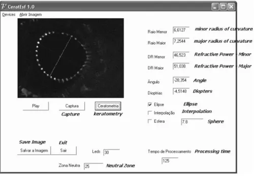
Figure 5 presents a picture of the software screen used for our own control and that is not presented to the surgeon.
It presents all the measurements that we should have access to, including the elapsing time of the captured
x Px i
N eeycm
Px i N e
y Py i
N eeycm Py i N e cm cm 0 0 0 0 = = = =
∑
∑
∑
∑
[ ] [ ][ ] [ ] (4)
x a y b 2 2 2 2 1
+ = (5)
S ri r
i
= −
=
∑
( )20 359
(6)
e kb a
= 1−
2
2; (7)
C=100 1( −e)% (8)
Representation of the ellipse used in the software's algorithm Figure 4
image and the presented result, in another words the processing time - "tempo de processamento"; the type of approximation being performed (elliptical); the polyno-mial interpolation required if the number of identified LEDs is not enough; the radius of curvature of the calibra-tion sphere; in this case 7.8 mm; the number of LEDs that could be identified in this case 30; the neutral zone -"zona neutra", where LEDs are not supposed to be identi-fied - in the center, for example; etc.
The interface software and calibrating system
A real time image is displayed at the OQO monitor with orientations for adjusting the target's axis and center. Fig-ure 6 presents the interface screen. There is a center guide denoted by 1 (small circle at the center of the image screen), as well as an angular guide, denoted by 2 (two rectangles orthogonally placed in the center of the image capturing screen). Region denoted by 3 is the location that the 36 reflected spots should be restrained.
There is a calibration button for the system. The calibra-tion of the system should be performed whenever its opti-cal components are removed and then replaced back in the microscope.
It consists in positioning a standard stainless sphere with radius of curvature of 7,895 mm ± 0,0025 mm at a pre-determined proper location; set the microscope to a desired magnification and capture its reflected image from the 36 light spots.
Keratometry and circularity (eccentricity) are presented whenever the image is captured (either by the mouse, voice command, or stepping pedal). The item referring to devices "dispositivos" on the top bar of figure 6, the sur-geon may choose one of these options.
Figure 7 presents a measurement performed in a patient during suturing. The surgeon has achieved 98% of
eccen-One of the software's screens used for our own control - it is not presented to the surgeon Figure 5
tricity, however, it shows that almost 1D of astigmatism remains.
Statement of ethical approval: This research has been approved by the Ethics Committee of the Clinical Hospi-tal of Ribeirão Preto - CAAE (Certificate for Ethical Appre-ciation) - reference number: 0212.0.004.000-09.
Results
The prototype has been submitted to standard tests, in order to check its reliability and its accuracy, prior to per-forming clinical trial on intra operative patients. Thus, it was first checked by using standard steal spheres; then its focal depth has been determined; followed by testing the prototype in post operative patients. The tests were per-formed to some extent to obtain data regarding the resid-ual astigmatism that corneal transplanted patients usresid-ually present 24 hours after the surgery, as well as comparing the keratometric data of these patients with a hand held commercial keratometer, supplying their correlation fac-tor; and finally using it intra operatively and checking the residual astigmatism within 24 hours after the surgery.
In order to know the accuracy of our system, 21 standard steal spheres have been analyzed. The correlation of our system and the data provided by the manufacturer of the standard spheres, in a range of 3.0000 mm - 17.0000 mm ± 0.0025 mm is 0.99.
Spheres with radius of curvature of 7.8 mm, which best represent the corneal model, is 90% reproducible, pre-senting an error of 3%. They are used for calibrating the system. For tested spheres with larger radius of curvature,
Screen presented to the surgeon during suturing Figure 6
Screen presented to the surgeon during suturing.
Real time surgery measurement of keratometry and eccen-tricity of a cataract surgery
Figure 7
the reproducibility is 95% and for smaller radius of curva-ture, it is 87%, due to critical centralization and alignment procedures.
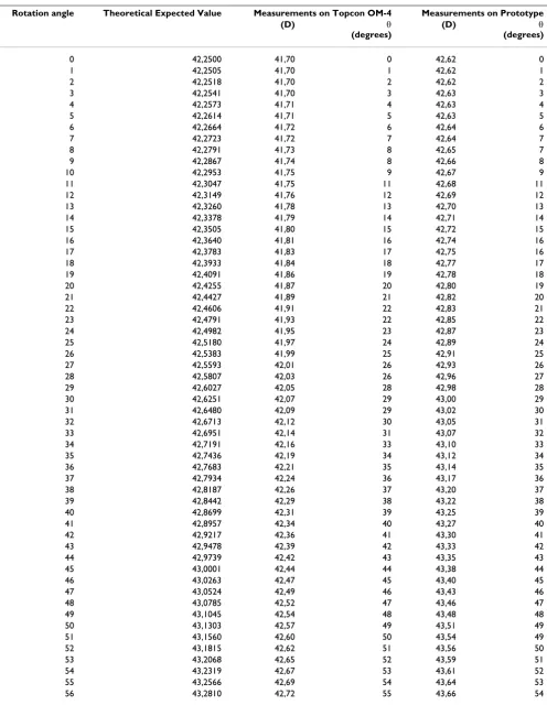
In order to evaluate the accuracy on measuring a distorted surface, three contact lenses have been distorted in a wedge, placed on a device that could rotate the lenses pre-cisely every 1° for all 360°, and have been used as trial surfaces. These lenses were measured in a Topcon OM-4 keratometer (three times each) and in our prototype. Table 1 presents the obtained data for lens 1.
The correlation factor between our system and Topcon OM-4 regarding the refractive power is r2 = 0,94, and r2 =
0,97 for the axis. Same procedure has been adopted for lenses 2 and 3 and the correlation factor was the same for these later ones.
Focus Depth
Bonnet [18] stated that keratometers should have focus depth inferior to 0.35 mm, with the intention that the pre-cision on the radius of curvature of the tested surface be 0.03 mm. The focus depth measurements were performed in our system using the 10× magnification (the most com-monly used magnification for the surgeries at our service), by focusing the image of the target onto the precision sphere. The measuring procedure was performed 60 times. For every test the system was completely defocused and then the image was brought into focus by two differ-ent users (30 times each). The focus depth in our hand held system is 0.08 mm, leading to a ± 0.25D error.
Keratometry Tests on Post Operative Patients and Circularity
In order to evaluate regular residual astigmatisms after a corneal transplantation and to understand the range of circularity that a surgeon may be working with, so that astigmatisms over 3D are not achieved, it is necessary to evaluate several eyes to have them as guiding data. Thus, 290 post operative patients, who were not submitted to the use of the prototype during surgery, had keratometry performed, as well as circularity measurements.
Keratometry
Keratometry in postoperative patients (290), who had not yet been submitted to the surgery with the support device for suturing information, were performed in our system and in a Topcon OM-4 keratometer. These individuals have been examined to provide information of the imme-diate postoperative residual astigmatism, as well as to compare the effectiveness of measurements performed with the prototype with a commercial available keratom-eter. The patients were tested on both systems. The patients were divided into 2 groups: corneal transplants (78%); and cataract (32%). Astigmatisms greater than 8D
were commonly reported. The data obtained for these astigmatisms vary from 0.75D - 11.85D. The average was 7.95D. Both systems were previously calibrated and the exams performed on both systems were 0.97 correlated.
These measurements were performed to assure that the system was in agreement with commercial available sys-tems to perform accurate keratometry.
Also 72 of these patients were submitted to keratometry in the sitting up position and in the lying down position, and were evaluated by the developed system and the Nidek Oculus Hand-held corneal topographer, which allows measurement on a lying down position. The keratometry obtained for these patients differ from the lying down position to the sitting up position. Keratomet-ric values were reported to show a discrepancy up to 1.5D in some cases.
The correlation factor between our system and the Nidek Oculus Hand-held corneal topographer for the sitting up position was r2 = 0.97 and for the lying down position r2
= 0.96.
Thus we have concluded that our prototype was able to perform keratometry in volunteer patients and the sur-geons were aware that the most important parameter to be used in the software for suturing purposes was the circu-larity.
Circularity
It has been registered for the 290 trial patients that in order to keep residual astigmatisms lesser than 3D for patients with corneas presenting radii of curvature around 7.8 mm, the minimum circularity that must be achieved is 97%; for flatter corneas (around 38D), the minimum cir-cularity to be achieved is 95%; and for a steeper cornea, the minimum required circularity is 99%.
Intraoperative Testing
Subsequently to the evaluation tests of the accuracy of the system itself, and knowing the expectation of pos opera-tive residual astigmatism, the prototype was tested in 14 patients during corneal transplant surgery.
Patients have been submitted to our system during sur-gery for guiding suturing by the circularity data. Then, the patients were submitted to our prototype and the Nidek Oculus Hand-held corneal topographer, 24 hours after the surgery.
Table 1: Obtained refractive power and astigmatism's assiociated axis for lens 1 in keratometer Topcon OM-4 and Prototype, and compared to theorethical data.
Rotation angle Theoretical Expected Value Measurements on Topcon OM-4 Measurements on Prototype
(D) θ
(degrees)
(D) θ
(degrees)
0 42,2500 41,70 0 42,62 0
1 42,2505 41,70 1 42,62 1
2 42,2518 41,70 2 42,62 2
3 42,2541 41,70 3 42,63 3
4 42,2573 41,71 4 42,63 4
5 42,2614 41,71 5 42,63 5
6 42,2664 41,72 6 42,64 6
7 42,2723 41,72 7 42,64 7
8 42,2791 41,73 8 42,65 7
9 42,2867 41,74 8 42,66 8
10 42,2953 41,75 9 42,67 9
11 42,3047 41,75 11 42,68 11
12 42,3149 41,76 12 42,69 12
13 42,3260 41,78 13 42,70 13
14 42,3378 41,79 14 42,71 14
15 42,3505 41,80 15 42,72 15
16 42,3640 41,81 16 42,74 16
17 42,3783 41,83 17 42,75 16
18 42,3933 41,84 18 42,77 17
19 42,4091 41,86 19 42,78 18
20 42,4255 41,87 20 42,80 19
21 42,4427 41,89 21 42,82 20
22 42,4606 41,91 22 42,83 21
23 42,4791 41,93 22 42,85 22
24 42,4982 41,95 23 42,87 23
25 42,5180 41,97 24 42,89 24
26 42,5383 41,99 25 42,91 25
27 42,5593 42,01 26 42,93 26
28 42,5807 42,03 26 42,96 27
29 42,6027 42,05 28 42,98 28
30 42,6251 42,07 29 43,00 29
31 42,6480 42,09 29 43,02 30
32 42,6713 42,12 30 43,05 31
33 42,6951 42,14 31 43,07 32
34 42,7191 42,16 33 43,10 33
35 42,7436 42,19 34 43,12 34
36 42,7683 42,21 35 43,14 35
37 42,7934 42,24 36 43,17 36
38 42,8187 42,26 37 43,20 37
39 42,8442 42,29 38 43,22 38
40 42,8699 42,31 39 43,25 39
41 42,8957 42,34 40 43,27 40
42 42,9217 42,36 41 43,30 41
43 42,9478 42,39 42 43,33 42
44 42,9739 42,42 43 43,35 43
45 43,0001 42,44 44 43,38 44
46 43,0263 42,47 45 43,40 45
47 43,0524 42,49 46 43,43 46
48 43,0785 42,52 47 43,46 47
49 43,1045 42,54 48 43,48 48
50 43,1303 42,57 49 43,51 49
51 43,1560 42,60 50 43,54 49
52 43,1815 42,62 51 43,56 50
53 43,2068 42,65 52 43,59 51
54 43,2319 42,67 53 43,61 52
55 43,2566 42,69 54 43,64 53
57 43,3051 42,74 56 43,69 55
58 43,3289 42,77 57 43,71 56
59 43,3522 42,79 58 43,73 57
60 43,3751 42,81 59 43,76 58
61 43,3975 42,83 60 43,78 59
62 43,4195 42,86 61 43,80 60
63 43,4409 42,88 62 43,82 61
64 43,4618 42,90 63 43,84 62
65 43,4822 42,92 64 43,86 63
66 43,5019 42,94 65 43,88 64
67 43,5211 42,96 66 43,90 65
68 43,5396 42,97 67 43,92 66
69 43,5574 42,99 68 43,94 67
70 43,5746 43,01 69 43,96 68
71 43,5911 43,02 70 43,97 69
72 43,6068 43,04 71 43,99 70
73 43,6218 43,05 72 44,01 71
74 43,6361 43,07 73 44,02 72
75 43,6496 43,08 74 44,03 73
76 43,6622 43,09 74 44,05 74
77 43,6741 43,11 75 44,06 75
78 43,6852 43,12 76 44,07 76
79 43,6954 43,13 77 44,08 77
80 43,7048 43,14 78 44,09 78
81 43,7133 43,15 79 44,10 79
82 43,7210 43,15 80 44,11 80
83 43,7277 43,16 81 44,11 81
84 43,7336 43,17 82 44,12 81
85 43,7386 43,17 83 44,12 82
86 43,7427 43,17 84 44,13 83
87 43,7459 43,18 85 44,13 84
88 43,7482 43,18 86 44,13 85
89 43,7495 43,18 87 44,13 86
90 43,7500 43,18 88 44,13 87
Table 1: Obtained refractive power and astigmatism's assiociated axis for lens 1 in keratometer Topcon OM-4 and Prototype, and compared to theorethical data. (Continued)
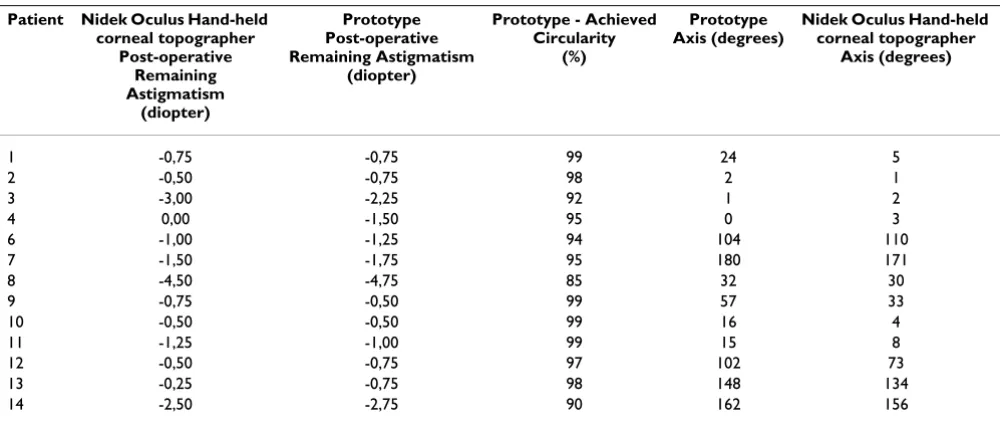
Table 2: Circularity measurements during surgery and postoperative keratometric measurements performed in 14 volunteer patients
Patient Nidek Oculus Hand-held corneal topographer
Post-operative Remaining Astigmatism
(diopter)
Prototype Post-operative Remaining Astigmatism
(diopter)
Prototype - Achieved Circularity
(%)
Prototype Axis (degrees)
Nidek Oculus Hand-held corneal topographer
Axis (degrees)
1 -0,75 -0,75 99 24 5
2 -0,50 -0,75 98 2 1
3 -3,00 -2,25 92 1 2
4 0,00 -1,50 95 0 3
6 -1,00 -1,25 94 104 110
7 -1,50 -1,75 95 180 171
8 -4,50 -4,75 85 32 30
9 -0,75 -0,50 99 57 33
10 -0,50 -0,50 99 16 4
11 -1,25 -1,00 99 15 8
12 -0,50 -0,75 97 102 73
13 -0,25 -0,75 98 148 134
patients in the sitting down position on the prototype and on the Nidek Oculus Hand-held corneal topographer.
The keratometry results have correlation factors of r2 =
0.92 for the refractive power and r2 = 0.99 for the axis,
with the sutures still on the cornea. Figure 8 presents the correlation factors of the performed measurements.
Discussion
The system is able to provide up to 23D of astigmatism (32D - 55D range), with accuracy of ± 0.25D.
Regarding the 14 tested patients, astigmatisms varying from 0.5D - 4.75D were obtained in the postoperative.
It can be noted that surgeons tend to tight the stitches, resulting in negative power astigmatisms.
The average of residual astigmatism for this relatively small number of patients was -1.4D, which leads to a pos-itive contribution of the use of this device for suturing.
This average is significantly lesser than the average of 8.0D obtained for the patients that were not submitted to sur-geries benefitted by the use of the prototype.
Considering figure 7, it may be noticed that high postop-erative astigmatisms tend to be easily induced by the irreg-ular manual suturing of the tissue. Even achieving a high eccentricity (98% of circularity) during the sutures, around 1D of astigmatism still remains.
It has been observed that circularity is a very intuitive parameter for the clinician to manage the stitches during surgery, but the surgeon should also be aware that it may be difficult to achieve circularity close to ideal (100%) depending on the curvature of the patient's cornea. For instance, in order to keep induced astigmatisms smaller then 3D, for patients having corneas with radii of curva-ture around 7.8 mm, a 97% of eccentricity should be achieved; for flatter corneas (refractive power of 38D) and more warped corneas (refractive power of 55D), eccentric-ities of 95% and 99%, respectively should be accom-plished. Therefore, for steeper corneas, high circularity should be achieved for best postoperative results.
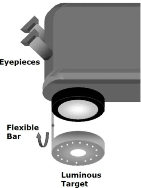
One of the limitations of this present prototype for clini-cal routine is that it is not of easy focusing or aligning the target during surgery. In order to overcome this problem, we suggest that the target should be attached to the objec-tive of the microscope, using a flexible rod, so that the tar-get could be folded down for its use and then folded back up while not using it, as presented in a schematic drawing in figure 9.
Conclusion
The obtained results encourage re-designing the prototype to turn it into a clinical routinely used prototype. Sugges-tions previously made (refer to figure 9) may be an easy solution for a more comfortable and free-hands use of the device. The system should be fixed at the microscope for a better ability in its use. Also focusing and centering becomes easier. Some of the surgeons have difficulty in aligning the system. However, we were not, at a first
Correlation factors between the postoperative measurements performed in patients (sitting down position) using the proto-type and the Nidek Oculus Hand-held corneal topographer
Figure 8
moment, concerned about using the instrument in a clin-ical routine, we were just enthusiastic on finding out if the orientation for suturing would be of any benefit for the patient, even at the very first post operative days (unstable astigmatism is quite frequent in this period), to provide better vision quality.
We have observed that there has been a significant reduc-tion in the post-operative astigmatism when the system is used during surgery.
Follow ups for the next 24 months are still being per-formed, but we have ultimately provided for these patients a better immediate post-operative quality of vision.
Now, we are adapting the system in the microscope, to turn it into a routine at the hospital that it has been tested.
These preliminary results obtained for the 14 patients may lead to an awareness that manual suture should be
care-fully performed in order to obtain better postoperative results related to remaining astigmatism.
Perhaps automated systems for suturing should be con-sidered in the near future.
Competing interests
The authors declare that they have no competing interests.
Authors' contributions
LV is the author of the concept idea and designed the opti-cal parts and the electronics project and has given some contribution on the software implemented; JJG is respon-sible for actually programming the software, SJFeS is the medical doctor who has evaluated most of the patients in the prototype, PS has implemented the electronics. All authors read and approved the final manuscript.
Acknowledgements
The authors would like to thank CNPq (477226/2003-5) - (Conselho Nacional de Desenvolvimento Científico e Tecnológico - "National Coun-sel of Technological and Scientific Development") for all the financial sup-port for this research and for some of the researchers.
References
1. Ballin N: Flieringa ring - The poor man's operating keratome-ter. Ophthalmic Surg 1981, 12:443-444.
2. Igarashi H, Akiba J, Hirokawa H, Yoshida A: Measurement of the radius of corneal curvature with the Maloney surgical keratometer. Am J Ophthalmol 1991, 112:211-212.
3. Troutman RC, Russa JAL: Surgical Microsystems, Inc. Indicating an asphericity of the cornea of an eye, US. Patent 4046463 . 4. Troutman R: Surgical keratometer in the management of
astigmatism in keratoplasty. Ann Ophthalmol 1987, 19:473-474. 5. Ventura L, Sousa SJF, Castro JC: Detection System For Ocular
Refractive Errors Measurements. Physics in Medicine and Biology
1998:1303-1316.
6. Morlet N, Maloof A, Wingate N, Lindsay P: Reliable keratometry with a new hand held surgical keratometer: calibration of the keratoscopic astigmatic ruler. Br J Ophthalmol 1998,
82(1):35-38.
7. Smith G, Atchison DA: The eye and Visual Optical Instruments Cam-bridge: University Press; 1941:175-179.
8. Ventura L, Riul C, Sousa SJF, De Groote JJ, Rosa Filho AB, Oliveira GCD: Corneal astigmatism measuring module for slit lamps. Phys Med Biol 2006:51.
9. Ventura L, Messias AMV, Sousa SJF, Coelho R: Automated Keratometry at Low Cost. IEEE - Engineering in Medicine & Biology Magazine 2000, 19(5):97-103.
10. Ventura L, Riul C, Sousa SJF: Optical projection mires for meas-urements of the radii of curvature of the cornea in biomicro-scopes. Applied Optics 2007, 46(30):.
11. Spalton DJ, Hitchings RA, Hunter PA: The Cornea. In Ophthalmology
Merck Sharp & Dohme International press; 1987.
12. Hogan MJ, Alvarado JA, Weddell E: Histology of the Human Eye Phila-delphia: WB Saunders; 1971.
13. Atchison A, Smith G: Optics of the Human Eye, Butterworth-Heinemann
2000.
14. Spalton DJ, Hitchings RA, Hunter PA, Tan JCH, Harry J: Atlas of Clinical Ophthalmology USA: Ed. Elselvier Mosby; 2005.
15. Jue B, Maurice DM: The Mechanical Properties of the Rabbit and Human Cornea. J Biomechanics 1986, 19(10):847-853. 16. Jongsma FHM, De Brabander J, Hendrikse F: Review and
Classifi-cation of Corneal Topographers. Lasers Med Sci 1999, 14:2-19. 17. Steinbruch A, Winterle P: Analitical Geometry McGraw Hill; 1987. 18. Bonnet R: La Topographie Cornéenne; Desroches Éditeur, Paris 1964.
Schematics of the suggested prototype for clinical routine use
Figure 9