35
Experimental Investigation of Submerged Vanes’ Shape… Barani and Sardo
Hydraulic
Structures
Shahid Chamran
Scientific
Professional
Quarterly
Spring
2013
Volume
1,
Issue
1,
Pages
35
‐
41
http://Jhs.scu.ac.ir
Experimental Investigation of Submerged Vanes’ Shape effect
on river-bend stability
1. Gholam-Abbass Barani
Professor of Civil Engineering Dept. Shahid Bahonar University of Kerman, Iran
2. Mehdi Shahrokhi Sardo
Msc Student of Civil Engineering Dept, Shahid Bahonar University of Kerman, Iran
Abstract
In river meandering, when flow passes through a bend, reduction of flow velocity and rising hydrostatic pressure cause super elevation phenomena at outer side and reduction of water surface at inner-side of the bend. A helical motion results, causing erosion of the outer side of the bend. Installation of submerged vanes on the stream bed can reduce erosion of the outer bank significantly. In this study, to investigate the effect of shape on van effectiveness, a physical model with a rectangular-section canal of 110*0.73*0.35(m) dimensions with two 90° and 180° bends, has been constructed. Overall 28 experiments were performed, using three shapes of submerged vanes (flat, angled and curved). These vanes were installed on the bed of 90° and 180° bends of model with arrays of one, two and three vanes in parallel and zigzag patterns. Three curved vanes installed in parallel pattern on 90°-bend and zigzag pattern on 180-bend can be more effective in river bank protection.
Keywords: sediment transport, submerged vanes, river bend, angled vanes, curved vanes.
1 Introduction
In river meandering, when flow passes through a end, due to the combination of transverse pressure gradient and centrifugal force, secondary flow evelops. The outer bank of the bend is subject to erosion due to high velocity of flow, while low elocity of near- bed flow towards the inner bank causes deposition (Voisin & Townsend 2002). Ifferent techniques have been used over the years to overcome the problem of erosion and deposition at river bends including construction of wing dams, dikes, revetments and dreading. A major difficulty with these techniques is the lack of analytical tools for predicting their effectiveness and impact o n t h e c h a n n e l ( O d g a a r d & W a n g 1 9 9 1 ) . Another technique consists of installing small submerged vanes on the stream bed to counter the flow spiral. This technique was introduced by Odgaard and kennedy(1983) for the first time to control outer bank erosion. The vanes set up a tip vortex similar to that of an airplane wing. These vanes modify the near-bed flow pattern and redistribute the flow and sediment transport within the canal cross section. The vortex extends downstream, gradually widening and decaying in strength due to the water velocity. The helical low created by the vortex causes transverse shear stresses on the river bed, resulting in sediment transport in a direction transverse to the flow direction. The transverse shear tresses cause sediment to be picked up on the vanes suction side and deposited on the pressure side( Barkdoll et al. 1999). The vanes are small-aspect-ratio foils placed along the outer ank, at angles of 10°-15° with the mean flow, to direct the
36
Experimental Investigation of Submerged Vanes’ Shape… Barani and Sardo
Hydraulic
Structures
Shahid Chamran
Scientific
Professional
Quarterly
Spring
2013
Volume
1,
Issue
1,
Pages
35
‐
41
http://Jhs.scu.ac.ir
three vanes in a row of parallel and zigzag patterns at two 90° and 180° bends.
2 Physical Model
A physical model of two 90° and 180° bends with two straight canals of 0.73-m width and 0.35-m height was constructed in an area of 600m2 at the Shahid Bahonar University. The 90° bend has inner and outer radii of 4.3-m and 5.03-m respectively. The 180° bend has the inner and outer radii of 2.37-m and 3.1-m respectively. Since the arc length to width ratio (L/B) for both 90° and 180° bends are more then 10, they fit the features of a freely meandering stream (Leopold et al. 1964; Struiksma et al. 1985). To e n s u r e t h a t t h e b e n d s d o n o t a f f e c t t h e i n f l o w characteristics; two straight canals 6.2-m and 7-m long was constructed between two bends and in continuation of the 180° bend respectively (Fig. 1).
Fig. 1. Plan view of the physical model.
To build the model, a 10-cm layer of cultivated soil was initially removed; and the ground surface was compacted. The base of the model 2.2-m wide was filled with a 50-cm layer of gravel; graded with an optical theodolite and compacted. Then, 10-cm concrete of 150 kg.m-3 cement covered the compacted surface. Canal sidewalls were built at a distance of 75-cm from each other, and 40-cm high. The canal bottom was covered with 5-cm concrete of 250 kg.m-3 cement, inside of canal sidewalls were coated by a 1-cm l a y e r o f f i n e m o r t a r t o b e c o m e uniformly smooth and bottom slope was regulated to 0.002, (Fig. 2).
Fig. 2. Details of section A-A.
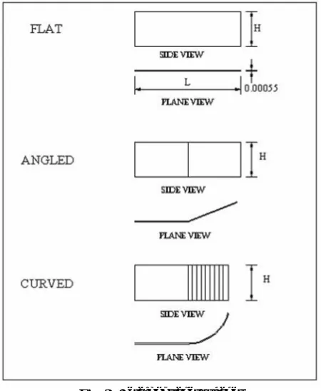
Water was supplied from a well by an electrical pump. A 90° triangular weir made of 0.55-mm thick galvanized plate was connected at the end of the model to measure flow rate. A 10-cm layer of sand with a median diameter of 1.6-mm a n d g e o m e t r i c s t a n d a r d deviation of 3.88 covered the bottom of model. Three shapes of submerged vanes (flat, angled and curved) 15-cm long and 13.5-cm wide made of 0.55-mm thick galvanized plates were used. Angled vanes connected of two equal flat parts with an angle of 22°, while the curved vanes contained a flat part 7.5 cm long and a curved part 7.5-cm long and 5-cm radius (Fig. 3).
Fig. 3. Detail of vanes’ shapes.
37
Experimental Investigation of Submerged Vanes’ Shape… Barani and Sardo
Hydraulic
Structures
Shahid Chamran
Scientific
Professional
Quarterly
Spring
2013
Volume
1,
Issue
1,
Pages
35
‐
41
http://Jhs.scu.ac.ir
the outer bank of bend. Vanes were installed in arrays of one, two and three vanes in a row. For arrays with two and three vanes in a row, they were installed in parallel and zigzag patterns. Plan view of three curved vanes in a row in parallel and zigzag patterns are shown in Figs 4 and 5.
Fig. 4. Plan view of curved-vanes installation on the bed of
model with 3-vanes in a row at parallel patterns
Fig. 5. Plan view of curved-vanes installation on the bed of
model with 3-vanes in a row at
zigzag patterns.
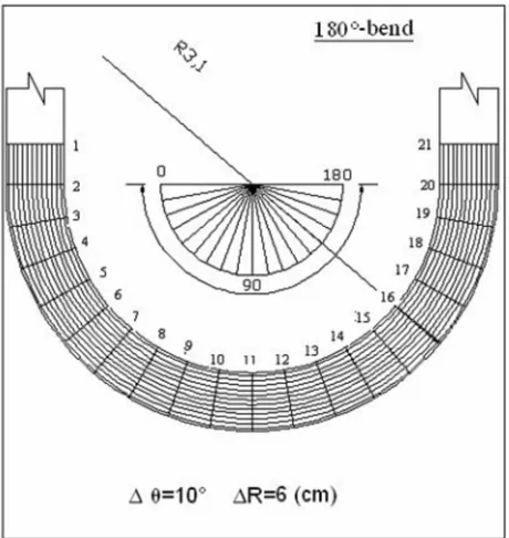
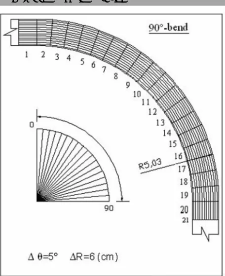
Vanes were installed on the canal bed at 50-cm longitudinal and 9.5-cm lateral separation. The distance between outer bank of canal and vanes was 17.5-cm for single vane array, and 9.5-cm for the other two arrays. For all experiments, water was carried through the model for 3-hours with flow rate of 0.35 m3/sec, and then it was cut off. Flow velocity was measured 0.5327 m/sec at 90° bend and 0.4795 m/sec at 180° bend, after that, bottom elevations at specific points (Δx =50-cm and Δy= 6-cm for straight part of canal, Δr = 6- cm and Δθ =5° for 90° bend and Δr = 6-cm and Δθ=10° for 180° bend, where r and θ are cylindrical coordinates) were measured to demonstrate bed topographic elevations of
bends. The total numbers of measured nodes in each experiment were 252 (21 stations longitudinally and 12 sections at transv erse direction), Figs. 6 and 7.
Fig. 6. Channel geometry and measured section of 1800 -
bend.
3 Experimental results
3. 1-Method of analysis
To evaluate the effect of vanes on the stability of curved banks, three indexes (percent of improvement, average lateral slope and dimensionless erosion depth) can be used. The percent of improvement can be defined as
(Voisin and
Townsend 2002):
Improvement(%) =
*100 [1]
Where (d0)max and (d0)avg are maximum and average erosion
38
Experimental Investigation of Submerged Vanes’ Shape… Barani and Sardo
Hydraulic
Structures
Shahid Chamran
Scientific
Professional
Quarterly
Spring
2013
Volume
1,
Issue
1,
Pages
35
‐
41
http://Jhs.scu.ac.ir
Fig. 7. Channel geometry and measured section of 900 -
bend.
For successful operation of vanes in bend outer bank protection, it is required that: the improvement percentage > 0.85, Savg 0.0 and (Ds / di ) 0.1, (Voisin & Townsend
002). 3. 2-The 90°-bend The first experiment was performed without vanes to come as a reference for comparison. Results showed that, along the one-third of bend, erosion was minor but increased from the middle of curved canal hrough the end (Fig. 8).
Fig. 8. Bed topography of 900-bend without vanes
installation.
The measured average erosion depths at the first one-third of curved canal was 0.717-mm and at the end of bend was 45.083-mm.The maximum erosion depth was measured equal to 47.5-mm. Installation of vanes on the bottom of the 90° bend reduced erosion depth significantly. Overall, installation of 3-vanes (compare to one or two vanes) in a row for all three shapes in both parallel and zigzag patterns resulted in better performance. As an example, experimental results using three arrays (one, two and three vanes in a row) of curved vanes in parallel pattern are presented in Fig. 9.
Fig. 9. Longitudinal bed profiles 3-cm from outer bank of
curved vanes in parallel pattern on 900-bend.
Curved and angled-shapes vanes were more effective than flat shape. (Figs. 10&11).
Fig. 10. Longitudinal bed profiles 3-cm from outer bank of
39
Experimental Investigation of Submerged Vanes’ Shape… Barani and Sardo
Hydraulic
Structures
Shahid Chamran
Scientific
Professional
Quarterly
Spring
2013
Volume
1,
Issue
1,
Pages
35
‐
41
http://Jhs.scu.ac.ir
Fig. 11. Longitudinal bed profiles 3-cm from outer bank of
3- vanes in a row in zigzag pattern on 900-bend.
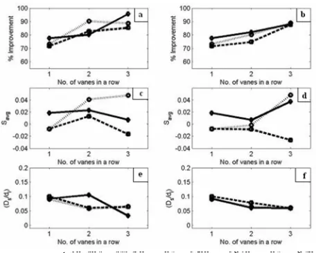
In an array of three parallel vanes in a row, curved and angled vanes reduced maximum erosion depths to 7.0-mm and 9.5-mm, and average erosion depths to 2.077-mm and 5.4-mm respectively. The computed erosion indexes of experiments performed on the 90°-bend was presented in Fig.12.
Fig. 12. Erosion indices of three shapes of vanes
(−−●−−flat,——◊—— curved and ....o…. angled) at
different arrays of parallel (a,c,& e) and zigzag (b, d & f) pattern installed at 900- bend.
3. 3-The 180°-bend
In the reference experiment without vanes, erosion started from the beginning of bend and increasing to a maximum of 44.5-mm at 55-90° of bend, and then decreased (Fig. 13).
Fig. 13.
Bed topography of 180
0-bend without vanes
installation.
The other experiments where performed using three types of vanes (flat, angled and curved) with arrays of one, two and three vanes in a row in parallel and zigzag patterns. Measured data have been used, the erosion indexes were computed, (Fig. 14).
Fig. 14. Erosion indices of three shapes of vanes
(−−●−−flat,——◊—— curved and ....o…. angled) at
different arrays of parallel (a,c,& e) and zigzag (b, d & f) pattern installed at 1800-bend.
40
Experimental Investigation of Submerged Vanes’ Shape… Barani and Sardo
Hydraulic
Structures
Shahid Chamran
Scientific
Professional
Quarterly
Spring
2013
Volume
1,
Issue
1,
Pages
35
‐
41
http://Jhs.scu.ac.ir
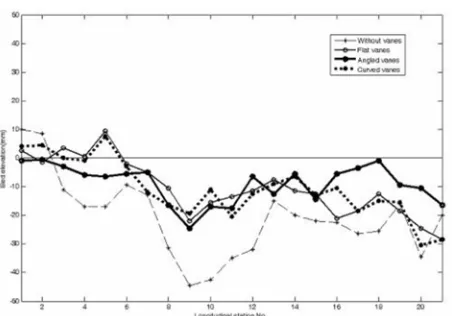
protection than angled shape (Fig. 16). For flat and curved vanes in zigzag
pattern with three vanes in a row, maximum erosion depths at 3-cm from the outer-bank wasmeasured equal to 17.5-mm and average erosion depths 9.036-mm and 8.033-mm, respectively.
Fig. 15. Longitudinal bed profiles 3-cm from outer bank of
curved vanes in in zigzag pattern on 1800-bend.
Fig. 16. Longitudinal bed profiles 3-cm from outer bank in
zigzag pattern on 1800-bend.
4 Conclusions
In this study, a physical model, include a canal with two bends (90° and 180°) has been built to investigate the effect of vanes' shapes and arrays on river bank protection. Three types of submerged vanes (flat, angled and curved) in arrays of one, two and three vanes in a row in parallel and zigzag patterns were used. Experimental results on 180°-bend, showed that three curved vanes in a row in zigzag pattern compare to the other states were more effective in
bank protection, and three flat-vanes in a row in zigzag pattern was stated at the second order.
The maximum erosion depth at 3-cm distance from the uter-bank was measured equal to 17.5-mm for both shapes, and the average erosion depths of these two types of vanes were measured 9.036-mm and 8.033-mm respectively. For three curved vanes in a row in zigzag pattern, the ratios of maximum erosion depth at bend outer bank to one-vane in a row was 62%, to two vanes in a row in parallel and zigzag patterns were 38% and 16.67% respectively, and to three-vanes in a row in parallel pattern was 28.58%. Results of experiments on 90°-bend showed that installations of three-vanes in a row compared to two and one three-vanes in a row create better performance in bank protection. In terms of vanes shapes and installation patterns three curved vanes in a row in parallel pattern at 90° bend create better protection at the bend outer bank.
References
[1] Voisin, A., and Townsend, R. D.(2002)."Model testing of Submerged Vanes in Strongly Curved Narrow Channel Bends." Cand. J. Civ.Eng. 29:37-42.
[2] Odgaard, A. J., and Wang, Y.(1991). "Sediment Management with Submerged Vanes. II:Applications." Journal of Hydraulic Engineering. ASCE, Vol. 117, No. 3, pp.284-302.
[3] Odgaard, A. J., and Kennedy, J. F.(1983)."River-bend bank Protection by Submerged Vanes." Journal of Hydraulic Engineering. ASCE,Vol. 109, No. 8, pp. 1161-1173
[4] Barkdoll, B. D., Ettema, R. and Odgaard, A. J., (1999). "Sediment control at lateral diversions:Limits and Enhancements to vane use." Journal of Hydraulic ngineering ASCE, Vol. 125, No. 8, pp. 862-870
[5] Odgaard, A. J., and Mosconi, C. E.(1987). “Streambank protection by Submerged Vanes,” Journal of Hydraulic Engineering ASCE, Vol. 113, No. 4, pp. 520-536, 1987. [6] Wang, Y., Odgaard, A. J., Melville, B.W. and Jain, S.C.(1996). “Sediment control at water intakes.” Journal of Hydraulic Engineering, ASCE, Vol. 122, No. 6, pp. 353-356.
[7] Marelius, F., and Sinha, S. K. (1998). "Eeperimental Investigation of flow past Submerged Vanes," Journal of Hydraulic Engineering, ASCE, Vol. 124, No. 5
[8] Johnson, P. A., Hey, R. D., Tessier, M. and Rosgen, D. L. (2001). “Use of vanes for control of scour at vertical wall abutments.” Journal of Hydraulic Engineering, ASCE, Vol. 127, No. 9, pp. 772-778.
[9] Johnson, P. A., Hey, R. D., Tessier, M. and Rosgen, D. L. (2003). "Barkdoll, B.D.(2002)., Discussion of: Use of vanes for control of scour at vertical wall abutments. Journal of Hyd.Eng.vol.127,No.9,September 2001,pp.772-778", Journal of Hydraulic Engineering, ASCE, Vol. 129, No. 3, pp. 246-247.
41
Experimental Investigation of Submerged Vanes’ Shape… Barani and Sardo
Hydraulic
Structures
Shahid Chamran
Scientific
Professional
Quarterly
Spring
2013
Volume
1,
Issue
1,
Pages
35
‐
41
http://Jhs.scu.ac.ir
echnology,Department of Civil Eng,Open Channel aboratory.
[11] Keat, T. S.,Guoliang, Y.,Yong, L. S.,and Chen, O. .(2005). "Flow Structure and Sediment Motion around Submerged Vanes in Open Channel." Journal of aterway,Port,Coastal,and Ocean Engineering., ASCE, Vol. 131, No. 3.
[12] Leopold, L. B., Wolman, M. G., and Miller, J. P.,(1964). "Fluvial processes in geomorphology." Freeman, San Francisco.
[13] Struiksma, N., (1985). " Prediction of 2D bed topography in rivers." Journal of Hydraulic