Http://www.ijetmr.com©International Journal of Engineering Technologies and Management Research [14]
EVALUATION OF BER PERFORMANCE OF FFT-OFDM FOR
WIRELESS COMMUNICATION NETWORKS
Engr. Muhammad Bello Abdullahi *1
*1 Department of Electrical and Electronic Engineering Technology, Abdu Gusau Polytechnic,
Talata Mafara, Zamfara State, Nigeria
Abstract:
Orthogonal Frequency Division Multiplexing (OFDM) is used to enhance Bit Error Rates (BER) performance for error free transmission in free space in free pace. OFDM-based systems operate in the hostile multipath radio environment, which allows efficient sharing of limited resources. This research work was designed, developed and simulated an FFT-OFDM based System using the basic blocks of Simulink in MATLAB/Simulink software, to enhance BER for error free transmission. The system was design using Fast Fourier transform (FFT) and Inverse Fast Fourier transform (IFFT).
This was achieved in backing of collection and review of high-quality research papers, which reported the latest research developments in OFDM communications networks, and its applications in future wireless systems. The research mitigated the noise enhancement effect. And many critical problems associated with the error transmission in wireless communication networks in the future. An error transmission in wireless systems is global issues and challenges that are still looking for efficient solutions. This research work would overcome the global issues and challenges facing the wireless communication network.
Keywords: MATLAB/Simulink; OFDM; BER and FFT.
Cite This Article: Engr. Muhammad Bello Abdullahi. (2019). “EVALUATION OF BER PERFORMANCE OF FFT-OFDM FOR WIRELESS COMMUNICATION NETWORKS.”
International Journal of Engineering Technologies and Management Research, 6(2), 14-26. DOI: https://doi.org/10.29121/ijetmr.v6.i2.2019.351.
1. Introduction
Http://www.ijetmr.com©International Journal of Engineering Technologies and Management Research [15]
Moreover, if you send single carrier frequency and the carrier frequency may become useless, due to either fading or other interference like ISC and ICI one station loses of service. But since OFDM takes one-word carrier and spreads it over several smaller carriers, so even if you have one fading in one specific frequency the station still has other useful channels, which can still convey the information. So instead of numerous adjacent symbols being destroyed, only some symbols are little bit distorted, spectral overlapping among sub-carriers is allowing improved spectral efficiency and used of steep band pass filter is eliminated [9]. In OFDM transmission where subcarriers are orthogonal to each other in frequency domain, it also distributes data over many numbers of carriers that are spread out at precise frequencies. This spacing gives the orthogonality in this method that prevents the demodulators from detecting other frequencies rather than their frequency. This process is demonstrated in figure 1 below by the guard interval and cyclic prefix. Cyclic prefix it reduces or even eliminates the ISI.
Figure 1: Guard Interval and cyclic Prefix [4].
The main aims and objectives of this research work are: 1) To design and develop OFDM systems
2) To enhance BER performance for error free transmission.
3) Finally, to achieve error free transmission in wireless network on the simulation results, that can be expanding and be used in wireless communication network.
2. Literature Review
This would section would provide an overview on the other research works that have been done on OFDM systems, which indicate the importance of OFDM systems in reducing or even eliminating noise effect and interference. Many researchers would give different design solution to the challenges associated with error in transmission. Many studies have been getting desired results which can be used to improve the system performance and reduce the effect of ISC and ICI which still need further enhancement.
2.1. The concept of OFDM
Http://www.ijetmr.com©International Journal of Engineering Technologies and Management Research [16]
overlapping sub-channels to avoid the used of higher speed equalization to avoid impulse noise and multiphase distortion and fully utilize bandwidth. This technology has been examined as the next generation transmission scheme for mobile wireless communications networks, as it most widely used communication technology in Wi-Fi and LTE [7].
Different users’ data transmit different sub-carriers; between sub-carriers is guard-band to avoid interference. In multi-carrier FDM the data of the user can be separated into multiple sub-stream and transmit them in parallel, to make the data rate high. While OFDM the sub-carriers are designed to be orthogonal, these allows sub-carriers to overlap and saved Bandwidth, that make data rate higher [1]. In OFDM the carriers are all generated by single transmitter in a special way that allow them to be tight much closer together and spend a much wider Bandwidth that means we can reduce or eliminate Guard-Band. And sub-carriers can be packed tightly without interference with each other and fall offset at band edges.
2.2. Related Works
Wireless channels can be considered as frequency selective when the bandwidth of signal is very wide, can reduction of ISI and ICI. And support multi user technique where it can accept many number of users showing spectral efficiency. Therefore, multiple streams can be transmitted in parallel while maintaining the relative phase and frequency connection between them. In a model system, some of these subcarriers can be saved as a guard band to avoid adjacent channel interference.
Below is the simplified OFDM system design which carried out using Simulink to simulate the FFT OFDM and DWT OFDM. The Simulink models for the two systems are illustrated in figures2. The first circuit designed using QPSK modulation scheme and second used QAM modulation scheme as can be seen the figures bellow. BPSK and QAM simulations the modulators and demodulators are placed in transmitter and receiver side accordingly in other OFDM system designs [5].
Figure 2: Simplified OFDM Simulink Model for DWT and FFT [5]
Http://www.ijetmr.com©International Journal of Engineering Technologies and Management Research [17]
Figure 3: BER Performance of OFDM using DWT and FFT for BPSK [4]
However, OFDM could be designed using a Discrete Wavelet Transforms (DWT) to replace in a position of FFT for frequency translation. The OFDM model for both DWT-OFDM and FFT-OFDM based system using 16-QAM, 32-QAM, 64- QAM and 128-QAM modulation techniques have been used in the developed OFDM model system. This paper has achieved better performance in terms of BER in DWT-IDWT based OFDM transmitter and that all the wavelet has better performance over the IFFT-FFT implication [2].
The parameters used includes: number of subcarriers of 64 (for FFT and DWT), modulation Scheme were 16-QAM and 64-QAM and channel was AWGN. Figure below shows the BER Performance of 16-QAM FFT/DWT OFDM system. To confirm the consistency of the MATALAB/Simulink simulations, OFDM symbols are made to get each BER value in the simulations. The simulation result showed in figure below which illustrates the performance of DWT-OFDM is much better than that of FFT-OFDM. In case of FFT-OFDM a BER of 0.0020 is achievable at 12 dB SNR, while DWT-OFDM gives BER of 0.0017 at 9 dB SNR. Table 1 shows numerical result of the simulation for 16-QAM FFT and DWT-OFDM system [2].
Http://www.ijetmr.com©International Journal of Engineering Technologies and Management Research [18]
Figure 4: BER Performance 16-QAM FFT/DWT OFDM system [2]
Both OFDM and SC-FDE transmission schemes were adopted by the standard and the BER are obtained for each repetition of the process of the energy per bit to noise power spectral density ratio (Eb/No) as illustrates in figure 5 below of the OFDM Simulink model system [3]
Figure 5: BER performance of OFDM vs I/Q Imbalances Phase Mismatch [3]
2.3. Summery
Many categories of OFDM system design were illustrated in the above review research works in which different modulations were used in their various designs which they used to obtain their various results for the effectiveness and desired results. However, I would like to conclude that, the results obtained in this research work of OFDM model system designed is much better than any of the above-mentioned results obtained by others work, in terms of BER performance.
3. Methodology
Http://www.ijetmr.com©International Journal of Engineering Technologies and Management Research [19] 3.1. OFDM Systems
The system would be designed and simulated on MATLAB/Simulink software to investigate the performance of OFDM in term of reducing or even eradicating error for error free transmission success.
3.2. Constellation Plots
The constellation plot in the data received with noise, the transmitted constellation diagram without Noise. It is believed that channel induced noise affects the received signal. Thus, errors are introduced in the demodulation and decoding processes. As expected, the received constellation plot does not return errors introduced by the channel. Hence, the points are incompatible with the lookup table QAM demodulation has been affected both phase and amplitude of the signal. The situation was mitigated after correcting some parameters in the transmission channel.
3.3. BERPerformance
The BER was very higher due to channel induce error Base on the simulation results obtained a constant error has been observed, which results in the strait lines in BER plot. That happens because OFDM transceiver designed in the first time does not have channel estimation. But after applying channel estimation on the OFDM system designed, the big degradation in BER was achieved. Therefore, it is important to include channel estimation to enables higher system performance.
4. Implementation
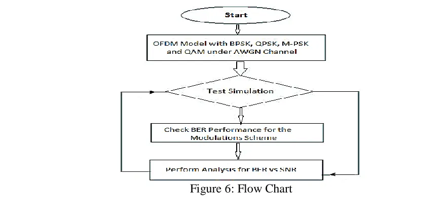
After the systems are designed and simulated this section provides comprehensible explanation about the final stages of the search work, and simulation results obtained by the system. The final stages of the project implementation are the BER performance of the simulation results as it can be seen clearly in figures below using different modulation schemes. The first stage of the design is flow chart which can be seen in figure 6 below.
Http://www.ijetmr.com©International Journal of Engineering Technologies and Management Research [20]
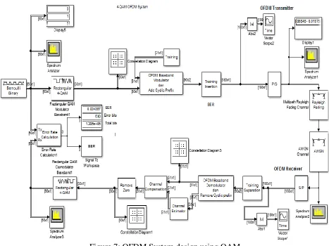
The second stage of the design is the FFT-OFDM system which can be seen in figure 7 below
Figure 7: OFDM System design using QAM
4.1. Simulation Results for BER Performance
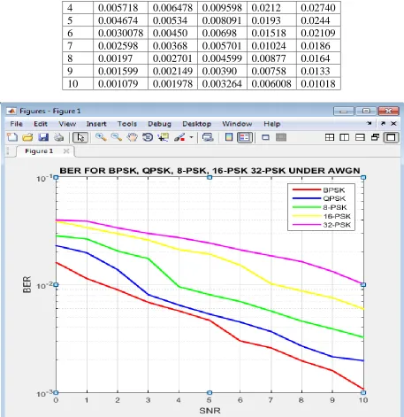
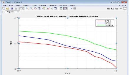
The simulation results shows that the higher the SNR in the OFDM system, the lower the BER as can be seen from tables 2, 3 and 4 and figures 8, 9 and 10 below which represent BPSK, QPSK, 8-PSK, 16-PSK and 32-PSK simulation results. 4-QAM, 8-QAM, 16-QAM and 32-QAM simulation results and BPSK, QPSK and QAM simulation results respectively. However, BPSK has better BER performance than QPSK and QPSK has better BER performance than QAM under the same transmission rate.
BPSK, QPSK and PSK Modulation
Table 2: BER vs SNR of (BPSK, QPSK, 8-PSK, 16-PSK and 32-PSK)
SNR BER
- BPSK QPSK 8-PSK 16-PSK 32-PSK
0 0.01611 0.0231 0.02845 0.0389 0.0399
1 0.01141 0.0198 0.02661 0.034 0.03897
2 0.00898 0.0138 0.0206 0.02984 0.03374
Http://www.ijetmr.com©International Journal of Engineering Technologies and Management Research [21]
4 0.005718 0.006478 0.009598 0.0212 0.02740 5 0.004674 0.00534 0.008091 0.0193 0.0244 6 0.0030078 0.00450 0.00698 0.01518 0.02109 7 0.002598 0.00368 0.005701 0.01024 0.0186 8 0.00197 0.002701 0.004599 0.00877 0.0164 9 0.001599 0.002149 0.00390 0.00758 0.0133 10 0.001079 0.001978 0.003264 0.006008 0.01018
Figure 8: BER of (BPSK, QPSK, 8-PSK, 16-PSK and 32-PSK)
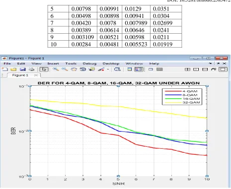
4-QAM to 32-QAM Modulation
Table 3: BER vs SNR (dB) for (4-QAM, 8-QAM, 16-QAM and 32-QAM)
SNR BER
- 4-QAM 8-QAM 16-QAM 32-QAM
0 0.02939 0.0355 0.0371 0.0489
1 0.0241 0.02899 0.0300 0.0458
2 0.0198 0.0226 0.0257 0.0422
3 0.0140 0.0199 0.0204 0.04091
Http://www.ijetmr.com©International Journal of Engineering Technologies and Management Research [22]
5 0.00798 0.00991 0.0129 0.0351
6 0.00498 0.00898 0.00941 0.0304
7 0.00420 0.0078 0.007989 0.02699
8 0.00389 0.00614 0.00646 0.0241
9 0.003109 0.00521 0.00598 0.0211 10 0.00284 0.00481 0.005523 0.01919
Figure 9: BER of 4-QAM, 8-QAM, 16-QAM and 32-QAM
BPSK, QPSK and 16-QAM Modulation
Table 4: Comparison of BER for BPSK, QPSK and16-QAM
SNR BER
- BPSK QPSK 16-QAM
0 0.01611 0.0231 0.0371
1 0.01141 0.0198 0.0300
2 0.00898 0.0138 0.0257
3 0.006871 0.008101 0.0204
4 0.005718 0.006478 0.0161
5 0.004674 0.00534 0.0129
6 0.0030078 0.00450 0.00941
7 0.002598 0.00368 0.007989
8 0.00197 0.002701 0.00646
9 0.001599 0.002149 0.00598
Http://www.ijetmr.com©International Journal of Engineering Technologies and Management Research [23]
Figure 10: Comparisons for BER Performance of BPSK, QPSK and QAM
4.2. Constellation Plots
The transmitted and received constellation plots for the BPSK, QPSK,8-PSK and 8-QAM Constellation Plots on the modulation results can be seen clearly in figures11, 12, 13 and 14 below, the transmitted constellation plot transmits without noise, while the received constellation plot do not return errors introduced by the channel.
BPSK Constellation Plots
Http://www.ijetmr.com©International Journal of Engineering Technologies and Management Research [24] QPSK Constellation Plots
Figure 12: QPSK (Transmitted Constellation Plots Figure: Received Constellation Plots)
8-PSK Constellation Plots
Figure 13: 8-PSK (Transmitted Constellation Plots Figure: Received Constellation Plots)
8-QAM Constellation Plots
Http://www.ijetmr.com©International Journal of Engineering Technologies and Management Research [25] 5. Conclusion
The test carryout and results obtained considering the two stages the simulation results obtained can be concluded the system performance. First the BER performance plots obtained when compared with theory and BER-Tool curve and analyzed the results, the results confirm to be succeeded where by a BER of 0.0010 is achievable at 10 dB SNR using FFT-OFDM.
Second stage is considering results of constellation diagrams obtained in both transmitter and receiver sides, which used to investigation and analyzed the level of error. The required result is obtained and aims were achieved, there the results obtained can used and be expanding and be used in wireless communication network.
6. Recommendations for Future Work
Under different modulations schemes, there were numerous recommendations for improving the OFDM system design. However, on the other research work an OFDM system design using DWT-OFDM system simulated results obtained was analyzed in terms of BER vs SNR. And investigated the performance of both DWT-OFDM and FFT-OFDM in the presence of phase noise; better result was achieved in terms of BER in DWT-OFDM system over the FFT-OFDM system. I therefore recommended the use of DWT-OFDM system in the next OFDM system design for better BER performance.
References
[1] Baltar, L. G. and Nossek, J. A. (eds.) (2012) OFDM 2012, 17th International OFDM Workshop
2012 (InOWo'12); Proceedings of. 'Multicarrier Systems: A Comparison between Filter Bank Based and Cyclic Prefix Based OFDM'
[2] BODHE, NARKHEDE, JOSHI, R. (2012) DESIGN OF SIMULINK MODEL FOR OFDM AND
COMPARISON OF FFTOFDM AND DWT-OFDM [online] available from<https://www.idc-online.com/technical_references/pdfs/electronic_engineering/DESIGN%20OF%20SIMULINK% 20MODEL%20FOR.pdf> [16 September 2018]
[3] Gomes, R., Al-Daher, Z., Hammoudeh, A., Sobaihi, K., Caldeirinha, R. and Fernandes, T. (2014)
'Performance And Evaluation Of OFDM And SC - FDE Over An AWGN Propagation Channel Under RF Impairments Using Simulink At 60Ghz'. 2014 Loughborough Antennas and Propagation Conference (LAPC)
[4] Gulzar, M., Nawaz, R. and Thapa, D. (2011) Implementation Of MIMO-OFDM System For
Wimax [online] available from
<http://www.diva-portal.org/smash/record.jsf?pid=diva2%3A421361&dswid=4817> [10 July 2018]
[5] Hariprasad, N. and Sundari, G. (2015) 'Comparative Analysis Of The BER Performance Of DWT
OFDM Over That Of FFT OFDM In Presence Of Phase Noise'. Robotics, Automation, Control and Embedded Systems (RACE), 2015 International Conference on [online]1-4.availablefrom <http://ieeexplore.ieee.org/stamp/stamp.jsp?tp=&arnumber=7097288> [1 July 2018]
[6] Kanpur, K. (2013) OFDM Simulator Using MATLAB [online] available from
<http://www.ijetae.com/files/Volume3Issue9/IJETAE_0913_79.pdf> [10 July 2018]
[7] Kulkarni, V. M. and Bhalchandra, A. S. (eds.) (2012) Computational Intelligence & Computing
Research (ICCIC), 2012 IEEE International Conference on. 'An Overview of various Techniques to Reduce the Peak-to-Average Power Ratio in Multicarrier Transmission Systems'
[8] LaSorte, N., Barnes, W. and Refai, H. (2008) 'The History Of Orthogonal Frequency Division
Http://www.ijetmr.com©International Journal of Engineering Technologies and Management Research [26]
[9] Mondragon-Torres, A., Kommi, M. and Battacharya, T. (2011) 'Architecture Exploration,
Development And Teaching Platform For Orthogonal Frequency Division Multiplexing (OFDM) Systems'.2011 Conference Record of the Forty Fifth Asilomar Conference on Signals, Systems and Computers (ASILOMAR)
*Corresponding author.
![Figure 1: Guard Interval and cyclic Prefix [4].](https://thumb-us.123doks.com/thumbv2/123dok_us/8977066.1886434/2.612.121.497.251.378/figure-guard-interval-cyclic-prefix.webp)
![Figure 2: Simplified OFDM Simulink Model for DWT and FFT [5]](https://thumb-us.123doks.com/thumbv2/123dok_us/8977066.1886434/3.612.78.542.485.640/figure-simplified-ofdm-simulink-model-for-dwt-fft.webp)
![Table 1: BER Performance for 16-Qam FFT/DWT OFDM system [2]](https://thumb-us.123doks.com/thumbv2/123dok_us/8977066.1886434/4.612.182.431.70.341/table-ber-performance-qam-fft-dwt-ofdm-system.webp)
![Figure 4: BER Performance 16-QAM FFT/DWT OFDM system [2]](https://thumb-us.123doks.com/thumbv2/123dok_us/8977066.1886434/5.612.131.483.70.255/figure-ber-performance-qam-fft-dwt-ofdm-system.webp)