DOI: 10.9781/ijimai.2016.425
Push Recovery for Humanoid Robot in Dynamic
Environment and Classifying the Data Using K-Mean
Anubha Parashar
1, Apoorva Parashar
2, Somya Goyal
3Vaish College of Engineering,Rohtak
Maharshi Dayanand University, Rohtak
PDM College of Engineering,Rohtak
Abstract — Push recovery is prime ability that is essential to be incorporated in the process of developing a robust humanoid robot to support bipedalism. In real environment it is very essential for humanoid robot to maintain balance. In this paper we are generating a control system and push recovery controller for humanoid robot walking. We apply different kind of pushes to humanoid robot and the algorithm that can bring a change in the walking stage to sustain walking. The simulation is done in 3D environment using Webots. This paper describes techniques for feature selection to foreshow push recovery for hip, ankle and knee joint. We train the system by K-Mean algorithm and testing is done on crouch data and tested results are reported. Random push data of humanoid robot is collected and classified to see whether push lie in safer region and then tested on given proposed system.
Keywords — Bipedal Walking, Push Recovery, Humanoid Robot, K-Mean Classification, Zero Moment Point, Linear Inverted Pendulum.
I. I
nTRoducTIonn
owa day’s human robots are developed to perform many humanactivities. Bipedal robots are comparable to human walking. Though we can say human locomotion seems effortless but it is exceptionally complex [1].
When we talk about the push recovery features in humanoid robot we face difficulties as compared to animals and humans. Humans and animals are completely versed where as humanoid robots have certain other features [2]. It’s contemplated to make a humanoid robot that can work smoothly and practically. There are many uncertain disturbances that emerge like push is one of the common problems that get created during locomotion. The goal of this paper is to search easy, lucid way for push recovery walking in humanoid robots. So we collect the push data by pushing humanoid robot from behind and we train the system by applying K-Mean algorithm and using crouch as data. Therefore we get a trained system which can analyse and work on any push recovery strategy. [18]- [20]
In this paper we apply four different types of pushes. The first difficulty that arises in humanoid robot is mainly due to ZMP (Zero Moment Point). A humanoid robot will be stable if and only if its ZMP is within the geometry of its foot.
In figure 2 the red line tells how the ZMP must lie within the sole of the robot through the complete motion. Green line shows that the trajectory of robot must emphasis on keeping the centre of gravity (COG) between the two feet of robot. Dark grey division show safe region of the foot for single support phase of humanoid motion. And light grey region shows safe region for double support phase of humanoid motion.
Fig. 1. Proposed Trajectory of Humanoid’s ZMP.
When an external push is applied to a humanoid robot we have 3 approaches, i.e. ankle, step and hip strategy shown in figure 2.
Fig. 2. Three basic balancing strategies in the presence of external forces.
It is troublesome to obtain perfect motion like human gait when there is high Degree of Freedom and variable mechanical structure of a human body. Inverted Pendulum Model (IPM) is utilized for gathering human motion gait [8] [9] [10] [11] robotics and biomechanics [12] [13] [14] [15] [16].The IPM presumes reaction force Counter-revolution obtained from the floor which is produce from the point and penetrates the COG (Centre of Gravity) of the IPM, resulting as absence of angular moments around COG. The linear acceleration of centre of mass will be more than that of the gravity acceleration when the humanoid is pushed very hardly on the Centre of Mass (COM). And as surface always has friction force therefore upper part of body will move faster than lower part of body. So in order to avoid this we eradicate the undesirable momentum induced from push therefore, humanoid robot may move steadily.
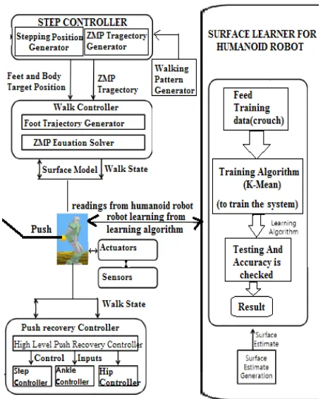
A. Proposed system
not. If it doesn’t fall in safe region, we make the humanoid robot learn by modifying the algorithm and to sustain its walking.
Fig. 3. Proposed System for Push Recovery for Humanoid Robot and Classifying the Data Using K-Mean.
B. Push recovery controller
The work of Push Recovery Controller (PRC) is to remove anxiety raised because of external disturbances or modelling error. On uneven surface chances of perturbations is very high so PRC is more required. PRC can be categorised into 3 categories (based on Fig.2)
1) Ankle Controller
To keep COM within the base support the torque is applied on the ankle joints by the ankle controller. It is effectuated as,
Δθ ankle = x ankle
here x (ankle) denotes the input of ankle controller and Δθ denotes the joint angle bias.
Step Controller
It controls the moves of the base to support in taking steps. With the relative target foot position a new step is inserted by overriding the step controller as x capture.
Hip Controller
It puts the angular acceleration of torso and limbs in use to create backward ground reaction force to pull COM back towards base support. To implement it we use,
Zhip(w) = τmaxi a(w) - 2τmaxi a(w-ZY1) + τmaxi a(w-ZY2)
where τmaxi is maximum torque that joint can apply, a(w) is unit step function, ZY1 is the time when torso stops accelerating and ZY2 is the time at which torso stops.
C. Hip strategy stability criteria
Hip strategy implements push recovery by intensifying the torque
of the hip joint to overcome the forces of push. The torque of the hip is applied closer to COM of the robot, and therefore produces greater reaction force [18]. The hip strategy can create greater counter forces therefore it is used for recovering from larger pushes in comparison with ankle strategy.
In general Linear Inverted Pendulum (LIP) is applied to humanoid robot [7] but this strategy deficit rotational inertia, which is very essential for hip strategy to balance push recovery. Therefore we exercise Angular Moment with Inverted Pendulum.
The classification of angular disturbance (in Fig. 4) can be done by control algorithm by comparing the sagittal and coronal torques [19]. The angular torque can be represented by following equation,
τ = τx cos (α) + τy sin (α)
Fig. 4. Angular Disturbance.
Figure 5 is used to find the control for humanoid. The motion of COG is controlled to make sure robot is stable during walking. The motion of COG of robot is affected by gravity and the contractility of the robot. Due to this the derivation of the robot’s kinematic equations [17] comes into picture.
Fig. 5. Linear Inverse Pendulum Model.
By analysing the humanoid robot’s COG in figure 4, the equation can be obtained, Mx”=f*sin (θ).
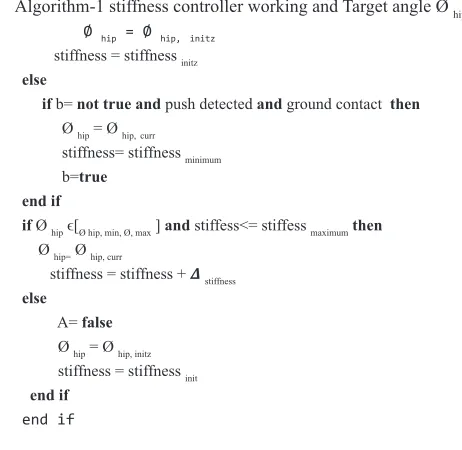
Algorithm-1 stiffness controller working and Target angle Ø hip
Ø hip = Ø hip, initz
stiffness = stiffness initz else
if b= not true and push detected and ground contact then Ø hip = Ø hip,curr
stiffness= stiffness minimum b=true
end if
if Ø hip ϵ[Ø hip, min, Ø, max ] and stiffess<= stiffess maximum then
Ø hip= Ø hip, curr
stiffness = stiffness + 𝜟stiffness else
A= false Ø hip = Ø hip, initz stiffness = stiffness init end if
end if
The stiffness controller gets real position and the strength of activation of joint. It then calculates the strength of activation and the target joint position. To calculate the torque for the joint, the output from the stiffness controllers is passed to low-level joint setup.
II. M
eThodologyA. To gather data and extract feature
Data is captured using body sensor based Human Motion Capture Device (HMCD) and potentiometer.Then data is collected using accelerometer sensor. It gives the meticulous acceleration and user can analyse the moment.
Fig. 6. hip ankle and knee joint.
Figure 6 shows the simulation of hip, ankle and knee joint with respect to time. Red curve is for hip, blue curve represent knee and green curve show ankle. Then we apply the push, i.e. four sorts of pushes are applied categorized as low, medium, medium high and high. Then the data is collected and Force sensing resistor(FSR 3105) is used to estimate push from back. To obtain joint angles of hip and knee we use inverse kinematics, and it employs to control the position of a humanoid’s extremities.
B. Joint angle calculation
Inverse kinematics is used to gather the result of link manipulator. Now the human leg is represented as two link manipulator in Fig.7 [8]
Fig.7. Two link manipulator.
The dynamics of 2-link manipulator is shown by, N (Φ(a)) Φ(a) + X(Φ(a), Φ(a)) + DΦ(a) = κ (a-P)
Where N is inertia matrix, X is centripetal and coriolis torque, κ is input torques and P is a dead line time. Each element is calculated as
N(Φ (a))= X(Φ(a),Φ(a)) = D= , κ= (a-L) = J1=I1+ (m1+4m2) i12 , J
2= I2+ (m1+4m2) i22 Β=2m2I1I2 , I1=1/3m1I12 , I2=1/3m2I22
Now the code is written for classification using Matlab. This is unsupervised classification technique. Appropriate area of training is selected for each class. Here .CSV (comma separated value) file is used to store training areas and the corresponding class.
C. Training
The system is trained using K-mean algorithm which is an unsupervised classification technique.
Algorithm 2: train the system using K-Mean algorithm
START
[1] Choose any arbitrary vector mean when a=0,
[2] Mean will be [w1, w2, w3…wz]a where z is no. of
cluster head.
[3] After this classification of raw data is done according to distance from mean at a=0.
[4] DO (Until threshold value is not reached that is
the convergence criteria is not satisfied).
[5] Again calculate mean vector for a=a+1 and consequently do the classification.
[6] Modify a=a+1;
[7] Convergence criteria
[8] Calculate the Euclidean distance ||w(a)-w(a-1)||<z
[9] Use w(a) as solution ELSE
[10] Go to step 5 END
UNTIL the data not classified/*classification gait= {normal, croach1, croach2, croach3, croach4}*/
Now the K-Mean algorithm (Algorithm-2) is framed in order to classify the crouch data, we make a minor modification in Algorithm-2, in order to classify the trajectories (in fig-1) of humanoid robot so as to find out which trajectory is safe push and which trajectory is not and we make four clusters (from fig-1) and see where trajectory lies i.e. grey, dark grey, green line or outside this.
So there will be 3 centroids and we use K-Mean algorithm to minimize an objective function,
,
is distance between data point ( ), is cluster centre
which indicates cluster centres of the distance of n data points. Suppose n is the sample feature vectors x1, x2... xn, and falls under k compact clusters. Say zi is in cluster i depicts mean of the vectors, where i represents 3 clusters i.e. in grey region, dark grey, green line or if not anyone then it lies outside this, If the clusters are properly distinguished, we can use a minimum-distance classifier to distinguish them, i.e. x belongs to cluster i if || x - zi || is smallest among all the distances of k.
D.
Classification
It is the selection feature where classification is done on the data set. Learning must be done in standard way in order to obtain the best results of system. It classifies the gait data where a set of data is already given as crouch data. The training is done using K-Mean algorithm then new push recovery data collected from humanoid robot is tested on the same system to predict the behavior of humanoid robot learning.
Different joint angles (knee, hip, and ankle) were captured and control reverse torques can be calculated for the joints in a bipedal humanoid using the following equation,
τ= W(Φ) θ″+ C(Φ, Φ ′)+ G(Φ)
where W(Φ) -inertial torque, C(Φ) - centripetal and coriolis forces, G(Φ) - gravitational force.
Once this is done, now the trajectories of push data is classified in order to check whether the humanoid robot lies in safe region or the humanoid robot cannot recover from the push.
III. e
xPeRIMenTAlR
esulTsIn simulated environment after training of push recovery controller we validate walking of humanoid robot.
A. Experimental setup
The simulation is done in WEBOTS, where the humanoid robot is equipped with accelerometer in the pelvic. In the experiment, similar motion of the simulation is produced to intensify the push force by modifying the COM position. We keep changing the pushing force and push data is analysed using classifier. As the data is collected by humanoid robot it is passed through the proposed algorithm and it shows the learning pattern of push recovery.
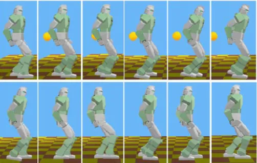
B. Push simulation
Here a rigid ball is used to push the humanoid robot from behind shown in figure 8[24].
Fig. 8. Simulation results as humanoid robot manages to walk normally by recovering from push strategy.
Figure 9 shows the influence inducement as an abrupt rise in the velocity of ball. To recover the humanoid robot the controller controls it and the unsupervised learning is done through K-Mean and manages it to it normal walking position.
Fig. 9. Velocity vs. Time diagram.
Once the push recovery strategy is applied, now the push recovery walking strategy is produced by controller and thus it will return to normal walking trajectory. Then ZMP controller generates centre of mass trajectory that will keep track of ZMP.
The different type of data set is collected when the robot is pushed from behind from different four strategies i.e. low, medium, medium high and high. When the classification of data is done the overall accuracy obtained is 60.275% shown in figure 10.
IV. d
IscussIonA. Performance of system
Webots is chosen for the simulation as it uses an accurate physics engine. It simulates gravity and frictional forces that influence the humanoid robot’s motion. Webots can easily simulate every position while applying gravity and external forces.
Fig. 10. Shows overall accuracy for training data set.
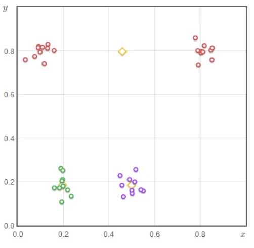
B. Conclusion
Figure 11 shows that different clusters could be shown according to COM that falls in classification in 4 different points while doing classification of Figure 1.
Fig.11. Data points clustered at 4 distinct positions.
When the humanoid robot is tested with respect to proposed system, it shows the better push recovery strategy. Therefore we used the K-Mean classification technique which gives accuracy rate up to 60%. Hence the push recovery data is classified properly and push recovery strategy is efficiently implied for humanoid robot.
So by the experimental comparisons, the proposed method can reduce perturbations up to large extend and it indicates that this method is an effective approach and can be use in the motion rules for humanoid robot walking and running.
R
efeRences[1] Aaron D. Ames, “Human-Inspired Control of Bipedal Walking Robots” IEEE TRANSACTIONS ON AUTOMATIC CONTROL, VOL. 59, NO. 5, MAY 2014 1115
[2] Wentao Mao, Jeong-Jung Kim and Ju-Jang Lee, “Continuous Steps toward Humanoid Push Recovery” Proceedings of the IEEE International Conference on Automation and Logistics Shenyang, China August 2009. [3] Vijay Bhaskar Semwal, Kaushik Mondal & G.C.Nandi “Robust
and Accurate Feature Selection for Humanoid Push Recovery and Classification: Deep learning Approach” Neural Computer & Application DOI 10.1007/s005.21-015-2089-3.
[4] Iamsa-at, S.; Horata, P., “Handwritten Character Recognition Using Histograms of Oriented Gradient Features in Deep Learning of Artificial Neural Network,” IT Convergence and Security (ICITCS), 2013 International Conference on , vol., no., pp.1,5, 16-18 Dec. 2013.
[5] Baptista, Darío, and Fernando Morgado-Dias. “A survey of artificial neural network training tools.” Neural Computing and Applications 23.3-4 (2013): 609-615.
[6] Chowdhury, Sujan, Brijesh Verma, and David Stockwell. “A novel texture feature based multiple classifier technique for roadside vegetation classification.” Expert Systems with Applications 42.12 (2015): 5047-5055.
[7] Taku Komura*, Akinori Nagano, Howard Leung, and Yoshihisa Shinagawa. “Simulating Pathological Gait Using the Enhanced Linear Inverted Pendulum Model.” IEEE TRANSACTIONS ON BIOMEDICAL ENGINEERING, VOL. 52, NO. 9, SEPTEMBER 2005.
[8] S. Kajita, F. Kanehiro, K. Kaneko, K. Fujiwara, K. Yokoi, and H.Hirukawa, “Biped Walking Pattern Generation by a Simple Threedimensional Inverted Pendulum Model,” Advanced Robotics, vol. 17, pp. 131-147, 2003.
[9] Albert, and W. Gerth, “Analytic Path Planning Algorithms for Bipedal Robots without a Trunk,” Journal of Intelligent and Robotic Systems, vol. 36, pp. 109-127, 2003.
[10] F. Miyazaki, S. Arimoto, “A Control Theoretic Study on Dynamical Biped Locomotion,” Journal of Dynamic Systems, Measurement, and Control, vol. 102, pp. 233-239, 1980.
[11] H. Miura, I. Shimoyama, “Dynamic Walk of A Biped,” Int. Journal of Robotics Research, vol. 3, pp. 60-74, 1984.
[12] F.L. Buczek, K. M. Cooney, M. R. Walker, M. J. Rainbow, M. C. Concha and J. O. Sanders, “Performance of an inverted pendulum model directly applied to normal human gait,” Clinical Biomechanics, vol. 21, no. 3, pp. 288-296, Mar. 2006.
[13] A. Karlsson and T. Persson, “The ankle strategy for postural controla comparison between a model-based and a marker-based method,” Computer Methods and Programs in Biomedicine, vol 52, no. 3, pp. 165-173, Mar. 1997.
[14] M. A. Townsend, “Biped gait stabilization via foot placement,” Journal of Biomechanics, vol. 18, no. 1, pp. 21-38, 1985.
[15] M. A. Townsend, “Dynamics and coordination of torso motions in human locomotion,” Journal of Biomechanics, vol 14, no. 11, pp. 727-738, 1981. [16] H. Hemami and C. L. Golliday, “The inverted pendulum and biped
stability,” Mathematical Biosciences, vol. 34, no. 1-2, pp. 95-110, 1977. [17] Akash, Shruti Chandra, Abba, G.C. Nandi, “Modeling a biped humanoid
robot using inverted pendulum towards push recovery,” International Conference on Communication, Information, and Computing Technology, Mumbai, India, 2012.
[18] Awais Yasin, Qiang Huang, Qian Xu, M. Saad Sultan, “Humanoid Robot Push recovery through foot placement,” International Conference on Mechatronics and Automation, Chengdu, China, 2012.
[19] Semwal, Vijay Bhaskar, and Gora Chand Nandi. “Toward Developing a Computational Model for Bipedal Push Recovery–A Brief,” IEEE Sensors Journal, vol. 15, no. 4, pp. 2021-2022, Jan. 2015.
[20] Semwal, Vijay Bhaskar, et al. “Biologically-inspired push recovery capable bipedal locomotion modeling through hybrid automata.” Robotics and Autonomous Systems 70 (2015): 181-190.
[21] Albertus Hendrawan Adiwahono, Chee-Meng Chew, Weiwei Huang, and Yu Zheng, “Push Recovery Controller for Bipedal Robot Walking” 2009 IEEE/ASME International Conference on Advanced Intelligent Mechatronics Suntec Convention and Exhibition Center Singapore, July 14-17, 2009.
Anubha Parashar is presently working as Assistant Professor in Manipal University Jaipur. She is graduated in Computer Science and Engineering from PDMCE Bahadurgarh and post graduated in Computer Science and Engineering from VCE Rohtak. Her research interests include Machine Learning, Bipedal Locomotion, Humanoid Robotics (locomotion & push recovery), Biometrics Gait,
Neural Networks, IOT, Artificial Intelligence and Soft
Apoorva Parashar is pursuing her B.Tech in Computer Science and Engineering from Maharshi Dayanand University, Rohtak. Her research interests include Machine Learning, Robotics, embedded system, IOT and Cloud Computing.
Somya Goyal is presently working as Assistant Professor in PDMCE Bahadurgarh. Her graduation and post graduation from VCE Rohtak. Her research interests include Software Engineering, Data Warehousing & Mining, Network
Technology, Artificial Intelligence & Knowledge Based