http: // www.ijrtsm.com© International Journal of Recent Technology Science & Management 51
ISSN : 2455-9679
[Nilesh et al. , 4(6), June 2019] Impact Factor : 2.865
IJRTSM
INTERNATIONAL JOURNAL OF RECENT TECHNOLOGY SCIENCE & MANAGEMENT
“SHELL AND TUBE HEAT EXCHANGER CFD ANALYSIS USING BAFFLES WITH
DIFFERENT ANGLE OF INCLINATION”
Nilesh Kumar
1,
Prof. Ravindra Mohan
21 P.G. Scholar, Dept. of Mechanical Engineering, IES, College Bhopal, MP, India
2 Assistant Professor, Dept. of Mechanical Engineering, IES, College Bhopal, MP, India
ABSTRACT
In present day shell and tube heat exchanger is the most common type heat exchanger widely use in oil refinery and other large chemical process, because it suits high pressure application. Firstly modeling done on CATIA software and the process in solving simulation consists of modeling and meshing the basic geometry of shell and tube heat exchanger using CFX package ANSYS 19.2. The objective of the project is design of shell and tube heat exchanger with series of baffles and study the flow and temperature field inside the shell using ANSYS software tools. The process in solving simulation consists of modeling and meshing the basic geometry of shell and tube heat exchanger using CFD package ANSYS 19.2. The objective of the project is design of shell and tube heat exchanger with baffle and study the flow and temperature field inside the shell using ANSYS software tools. The heat exchanger contains 5 tubes and 600 mm length shell diameter 90 mm. The helix angle of baffle will be varied from 900, 300 to 450. In simulation will show how the pressure vary in shell due to different helix angle and flow rate. The flow pattern in the shell side of the heat exchanger with continuous baffles was forced to be rotational and Baffles Series due to the geometry of the continuous baffles, which results in a significant increase in heat transfer coefficient per unit pressure drop in the heat exchanger.
Key Words: Baffles, CFD, ANSYS, CATIA, Heat transfer, Flow
I.
I
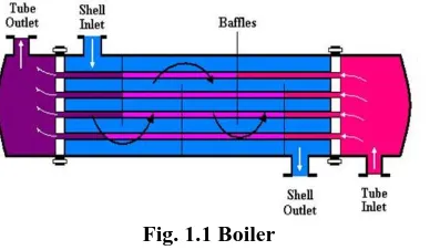
NTRODUCTIONHeat exchanger is a device that continuously transfers heat from one medium to other medium in order to carry process energy. The purpose of constructing a heat exchanger is to get an efficient method of heat transfer from one fluid to another, by direct contact or by indirect contact. Heat exchangers are one of the mostly used equipment in the process industries. Heat exchangers are used to transfer heat between two process streams. One can realize their usage that any process which involve cooling, heating, condensation, boiling or
evaporation will require a heat exchanger for these purpose. Process fluids, usually are heated or cooled before the process or undergo a phase change. Different heat exchangers are named according to their application. For example, heat exchangers being used to condense are known as condensers, similarly heat exchanger for boiling purposes are called boilers. Shell and tube type heat exchanger consists of a number of tubes through which one fluid flows. Another fluid flows through the shell which
http: // www.ijrtsm.com© International Journal of Recent Technology Science & Management 52
ISSN : 2455-9679
[Nilesh et al. , 4(6), June 2019] Impact Factor : 2.865
header sheets, gaskets etc. The heat exchange between the two fluids takes through the wall of the tubes.
II.
METHODOLOGY
CFD is a sophisticated computationally-based design and analysis technique. CFD software gives you the power to simulate flows of gases and liquids, heat and mass transfer, moving bodies, multiphase physics, chemical reaction, fluid-structure interaction and acoustics through computer modeling. This software can also build a virtual prototype of the system or device before can be apply to real-world physics and chemistry to the model, and the software will provide with images and data, which predict the performance of that design.
Fig.2.1 Methodology Diagram
CFD analysis of helical coil heat exchanger using Ansys 17.0, Cad model Generation of 3D model by using CATIA V 5R20 and exporting to the IGES. and then import in ANSYS fluent 19.2.
PRE PROCESSING:
Create geometry and mesh for solving problem
CAD model
Generation of 3D model by using CATIA ver 5.0 R20
FVM approach:-
By this method we can solve algebraic equation to get initial solution.
Turbulence dissipation rate second order(ɛ)
SOLUTION INITIALIZATION:-
Initialized the solution to get the initial solution for the problem.
By using SIMPLE solver ( Semi – implicit method for pressure linked equation).
RUN SOLUTION
Run the solution by giving 300 no of iteration for solution to converge.
Set the transportation equation that needs to be solved. This can be solved by using ANSYS Fluent 14.0 in Fluent setup
Set the fluid property
Set the boundary conditions
Set the Source term (Pressure)
SOLUTION
Solustion Method
Pressure Velocity coupling scheme
For 2D Problem we use Stream Function Vortices approach.
For 3D Problem we use Primitive variable approach.
http: // www.ijrtsm.com© International Journal of Recent Technology Science & Management 53
ISSN : 2455-9679
[Nilesh et al. , 4(6), June 2019] Impact Factor : 2.865
Turbulence Modeling
K-ɛ turbulence model for turbulent flow equation Momentum second orderTurbulence Kinetic energy second order (K)
POST PROCESSING:-
Post Processing:- For viewing and interpretation of Result, the result can be viewed in various formats like graph, value, animation etc.
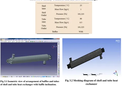
Table. 1 Geometric dimensions of shell and tube heat exchanger
Heat Exchanger length, L 600 mm
Shell inner diameter, Di 90 mm
Tube outer diameter, do 14mm
Tube bundle geometry and pitch 30mm
No. of tubes, Nt 5
No. of tubes, Nb 5
Central Baffles spacing 86 mm
Baffle inclination angle, Ɵ 90⁰ to 30⁰ and 45⁰
III.
SIMULATION
&
MODELING
Table 3.1 Boundary Condition shell and tube heat exchanger
Fig 3.1 Isometric view of arrangement of baffles and tubes of shell and tube heat exchanger with baffle inclination.
http: // www.ijrtsm.com© International Journal of Recent Technology Science & Management 54
ISSN : 2455-9679
[Nilesh et al. , 4(6), June 2019] Impact Factor : 2.865
3.1 90°Degree Baffle Inclination Angle
3.2 30°Degree Baffle Inclination Angle
Fig.3.3 Heat exchanger model boundary conditions with 90° Inclination baffles
Fig.3.4 Heat exchanger90° Inclination baffles Total temperature results
Fig.3.5 Heat exchanger 90° Inclination baffles Total pressure results
Fig.3.6 Heat exchanger 90° Inclination baffles Turbulence kinectic energy results
Fig.3.7 Heat exchanger 90° Inclination baffles velocity results
Fig.3.8 Heat exchanger 0° Inclination baffles streamline velocity results
Fig.3.9 Heat exchanger 30° Inclination baffles Total pressure results
http: // www.ijrtsm.com© International Journal of Recent Technology Science & Management 55
ISSN : 2455-9679
[Nilesh et al. , 4(6), June 2019] Impact Factor : 2.865
3.3 45° degree Baffle Inclination Angle
Fig.3.11 Heat exchanger 30° Inclination baffles Turbulence kinectic energy results
Fig.3.12 Heat exchanger 30° Inclination baffles streamline velocity results
Fig.3.14 Heat exchanger 45° Inclination baffles total pressure results
Fig.3.15 Heat exchanger 45° Inclination baffles total temperature results
Fig.3.16 Heat exchanger 45° Inclination baffles turbulence kintic energy results
Fig.3.17 Heat exchanger 45° Inclination baffles velocity results
http: // www.ijrtsm.com© International Journal of Recent Technology Science & Management 56
ISSN : 2455-9679
[Nilesh et al. , 4(6), June 2019] Impact Factor : 2.865
IV.
RESULT
&DISCUSSION
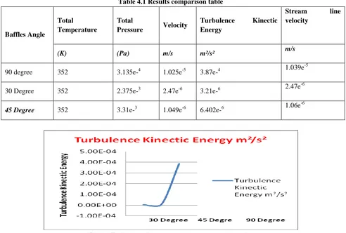
We have take will and tube types heat exchanger so we have consider here three case .
Case1:90° degree inclination of baffles, here we find from CFD thermal arrangement enable we to discover diverse thermal parameter like that all out temperature, complete weight, disturbance kinetic vitality, speed and streamline speed. So the estimation of all out temperature, all out weight, Turbulence Kinectic Energy, speed and streamline speed are separately similar to that 352 K, 3.135e-4, 1.025e-5, 3.87e-4 m2/s2and 1.039e-5m/s
Case2: 30°degree inclination of baffles, here we find from CFD thermal arrangement enable we to discover distinctive thermal parameter like that all out temperature, absolute weight, disturbance kinetic vitality, speed and streamline speed. So the estimation of all out temperature, complete weight, Turbulence Kinectic Energy, speed and streamline speed are separately similar to that 352 K, 2.375e-3 , 2.47e-6 , 3.21e-6, 2.47e-6
Case3: 45°degree inclination of baffles, here we find from CFD thermal arrangement enable we to discover diverse thermal parameter like that absolute temperature, all out weight, choppiness kinetic vitality, speed and streamline speed. So the estimation of all out temperature, complete weight Turbulence Kinectic Energy, speed and streamline speed are separately similar to that 352K, 3.31e-3, 1.049e-6, 6.402e-6, 1.06e-6
So we locate all thermal parameter and here we have chosen 30°degree inclination of baffles shell and cylinder types heat exchanger with supplant leaving 90° degree inclination of baffles shell and cylinder type heat exchanger.
Presently here we have approve our outcome from "Sebastião José dos Santos Filho, JosediteSaraiva de Souza, Antonio Gilson Barbosa de Lima".
Our outcome is great contrast with these creator. so we can proposed this venture work in future.
Table 4.1 Results comparison table
Baffles Angle
Total
Temperature
Total
Pressure Velocity
Turbulence Kinectic
Energy
Stream line
velocity
(K) (Pa) m/s m²/s² m/s
90 degree 352 3.135e-4 1.025e-5 3.87e-4 1.039e
-5
30 Degree 352 2.375e-3 2.47e-6 3.21e-6 2.47e
-6
45 Degree 352 3.31e-3 1.049e-6 6.402e-6 1.06e
-6
http: // www.ijrtsm.com© International Journal of Recent Technology Science & Management 57
ISSN : 2455-9679
[Nilesh et al. , 4(6), June 2019] Impact Factor : 2.865
V.
CONCLUSION
This model can likewise be enhanced by utilizing Nusselt number and Reynolds push model, yet with higher computational hypothesis. Besides the upgrade divider work are not use in this undertaking, but rather they can be exceptionally valuable. The heat exchange is poor in light of the fact that a large portion of the fluid goes without the cooperation with baffles. In this way the design can be altered for better heat move in two different ways either the diminishing the shell measurement, so it will be a legitimate contact with the baffle or by expanding the baffle so baffles will be appropriate contact with the shell. It is on the grounds that the heat exchange territory isn't used proficiently. So We can seen that when edge of inclination baffle will be expanded at that point heat exchanged we found that most extreme. Here we use 90⁰, 30⁰ and 45⁰ degree inclination edge with baffles and 45⁰ degree inclination baffles we discovered least disturbance esteem contrast with 90⁰ degree and 30⁰ degree inclination of baffles.
As announced in the advancement of this article, the design of a shell-and-cylinder heat exchanger is very mind boggling, requiring a decent learning with respect to its factors essentially in regards to their speed. Be that as it may, our center was identified with flow rates and temperatures pointing this investigation for a later work.
he conclusions about this work were:
Current lines, weight and temperature fields carry on not surprisingly computationally To discover Turbulence kinetic vitality.
The baffles nearness fundamentally expands the thermal trade proficiency. Fig.4.2 Stream line velocity comparison graph
http: // www.ijrtsm.com© International Journal of Recent Technology Science & Management 58
ISSN : 2455-9679
[Nilesh et al. , 4(6), June 2019] Impact Factor : 2.865
REFERENCES
1. A.O. Adelaja, S. J. Ojolo and M. G. Sobamowo, “Computer Aided Analysis of Thermal and Mechanical Design of Shell and Tube Heat Exchangers”, Advanced Materials Vol. 367 (2012) pp 731-737 © (2012) Trans Tech Publications, Switzerland.
2. Yusuf Ali Kara, OzbilenGuraras, “A computer program for designing of Shell and tube heat exchanger”, Applied Thermal Engineering 24(2004) 1797–1805.
3. Rajagapal THUNDIL KARUPPA RAJ and Srikanth GANNE, “Shell side numericalanalysis of a shell and tube heat exchanger considering the effects of baffle inclination angle on fluid flow”, ThundilKaruppa Raj, R., et al.: Shell Side Numerical Analysis of a Shell and Tube Heat Exchanger ,THERMAL SCIENCE: Year 2012, Vol. 16, No. 4, pp. 1165-1174.
4. S. NoieBaghban, M. Moghiman and E. Salehi, “ Thermal analysis of shell-side flow of shell-and tube heat exchanger using experimental and theoretical methods” (Received: October 1, 1998 - Accepted in Revised Form: June 3, 1999).
5. A.GopiChand, Prof.A.V.N.L.Sharma ,G.Vijay Kumar, A.Srividya, “ Thermal analysis of shell and tube heat exchanger using mat lab and floefd software”, Volume: 1 Issue: 3 276 – 281, ISSN: 2319 – 1163.
6. Hari Haran, Ravindra Reddy and Sreehari, “Thermal Analysis of Shell and Tube Heat Exchanger Using C and Ansys” , International Journal of Computer Trends and Technology (IJCTT) – volume 4 Issue 7–July 2013.
7. J. Li and G.P. Peterson, “Experimental measurements of fluid flow and heat transferring micro-channel cooling passages in a chip substrate, Proceedings of the ASME International Electronics Packaging Conference in Binghamton, NY, USA, ASMEpublications, 1993, Vol. 4-2, p. 685–692.
8. Pfund, D., Rector, D., Shekarriz, A., Popescu, A., and Welty, J., “Pressure drop measurements in a micro channel”, AICHE Journal, 2000, Vol. 46(8), p. 1496–1507.
9. Rahman, Vafai ,M.M. and Gui, F., Design, fabrication, and testing of micro channel heat sinks for aircraft avionics cooling”, Proceedings of the Intersociety Energy Conversion Engineering Conference, 1993, Vol. 1, p. 1–6.
10. Wei and Joshi, “Enhanced heat transfer in the entrance region of micro channels”,Proceedings of the Intersociety Energy Conversion Engineering Conference, 1995, p. 289–294.
11. Gui and Anderson, “Single-phase liquid friction factors in micro channels”,International Journal of Thermal Sciences, 2005