103
Dynamic behaviour of ground-supported tanks considering
fluid-soil-structure interaction (Case study: southern parts of Tehran)
Ghanbari, A. and Abbasi Maedeh, P.*
Faculty of Engineering, Kharazmi University, Karaj, Iran
Received: 23 Aug. 2014 Accepted: 6 Nov. 2014
ABSTRACT: Regarding the importance of the prevention of hazards and adverse environmental impacts in industrial and populated areas such as southern parts of Tehran city, the response of impulsive period ground-supported tanks were assessed. Having considered the study area's soil properties, the response of ground-supported tanks was modelled. Regarding the soil properties of southern parts of Tehran, the soil structure interaction method explained in FEMA 368 revealed that the interactional impulsive period (~T) was greater than non-interactional one (T). In addition, results showed that Poisson's ratio and stiffness ratio (K/Kx) were more effective regarding the response of
the interactional period of ground-supported tank systems. According to the achieved results, the liquid mass density effect on impulsive period was as low as the thickness of the ground-supported walls effect. Results showed that wall materials significantly affected the variation within the impulsive period. Generally, concrete materials were shown to be more periodic than steel materials. Overall, in southern parts of Tehran, when the soil fluid structure interaction method was used, the period increased from 1 to up to 3.6 times greater than the normal impulsive period.
Key words: Ground-supported tanks, Impulsive period, Interaction, Tehran
INTRODUCTION
Liquid storage tanks are essential structures in water as well as oil and gas industries. Several cases of damage to tanks have been observed in the past as a result of earthquakes. Water supply is essential for controlling fires that may occur during earthquakes, which can cause a great deal of damage and the loss of lives (Aslam and Godden, 1979). Ground-supported tanks are critical and strategic structures, and damage to them during earthquakes may endanger drinking water supply, cause failure in preventing large fires and contribute to substantial economic loss (AWWA M-42, 2013). Regarding the importance of these systems, particularly their seismic safety for avoiding adverse
*Corresponding author E-mail: [email protected]
consequences such as fires, explosions and environment pollution, it a better understanding of their seismic behaviour appears necessary.
Ground-supported tanks should remain functional in post-earthquake periods to ensure that a clean water supply is available in earthquake-affected regions (Oyarzo-Vera et al., 2012). Nevertheless, several tanks have been damaged or collapsed as a result of past earthquakes (Taniguchi, 2004). Interaction of the tanks with soil and water or other liquids results in the modification of the system's dynamic properties, which in turn alters its seismic response (Veletsos and Meek, 1974; Veletsos and Tang, 1990).
104
the field of computational engineering in recent years (Zienkiewicz and Bettes, 1978; Youssef, 1998). This area is of interest to a variety of engineering obstacles, ranging from the flow in blood vessels, aerodynamics and of course the interaction between water and civil engineering structures. The typical civil engineering application of fluid-structure interaction (FSI) encountered in many facilities is obtained at seismic loading, where the ground-supported tank facilities consists of water-filled pools of various sizes, for example, spent fuel and condensation pools (Rai, 2002). Seismic studies of intake-outlet tanks should therefore incorporate the effects of fluid- and soil-structure-interaction (Chen and Barber, 1976).
The first effect of FSI is water mass will reduce the natural frequencies compared to the original structure (Haroun and Ellaithy, 1985). The second effect is that water will contribute to hydrostatic and hydrodynamic water pressure that will act on the walls of the tanks due to wave propagation in the fluid (Goto and Shirasuna, 1980; NZS, 2004; NZSEE, 2009). With regard to the dynamic analysis of rectangular tanks, several works have been reported. Kianoush and Chen (2006) and Livaoglu (2008) evaluated the dynamic behaviour of fluid-rectangular-tank-soil-foundation systems using a simple seismic analysis procedure, based on Housner’s two mass approximations, with results showing that displacements and base shear forces generally decreased with decreasing soil stiffness. However, embedment, wall flexibility and soil-structure interaction (SSI) did not considerably affect sloshing displacement.
Storage tanks are very stiff structures with a very short impulsive period (a few tenths of a second).When these structures are placed on soft soils, SFSI (soil-fluid-structure interaction) will significantly determine the seismic behaviour of storage tanks (Naderi et al., 2013). Veletsos and Meek (1974) identified two main factors to
explain the difference in the seismic behaviour between the same structure placed on firm soil and on soft soil. The first of these aspects was that structures on a flexible base have more degrees of freedom and therefor, different dynamic characteristics than structures on a rigid base. The second aspect indicated that a part of the vibrational energy of a structure placed on a flexible base will be dissipated by the radiation of waves into the supporting medium and by damping in the foundation material.
Veletsos and Tang (1990) also investigated the SFSI of storage tanks. In this instance, they solved the problem in the frequency domain, included the foundation of the tank and also considered impulsive and convective modes of vibration. Their conclusions were:
a) a decrease in the natural frequency of the system when SFSI was considered;
b) an increase of the damping of the system, reducing the peaks in the seismic response;
c) the reduction in natural frequency was greater for slender tanks than for broad tanks, because the rocking component of the foundation motion was more important for slender tanks;
d) the reduction in peak response was more significant for short, broad tanks than for tall, slender tanks, because these type of tanks were able to dissipate more energy by radiation damping;
e) the effects of SFSI for convective modes were negligible. The authors also stated that SFSI was mainly governed by the relative stiffness of the supporting medium, i.e., by the structure- stiffness to soil-stiffness ratio.
For this reason, when this type of structure is placed on soft soils, SFSI will have an important role in the seismic response of storage tanks.
ground-105
supported tanks, the thickness of tank walls, wall material effects and H/D ratio effect on the natural periods of ground-supported tanks. At the conclusion of this research we will check and compare the natural periods with and without considering SSI on the structure. When checking one of the SSI models explained in material and methods section, we expected to find increasing or decreasing impulsive SSI ratios (~T/T) with different soil stiffness, as well as other parameters. Some environmental and civil engineering associations’ laws have limited the capacity of tanks. The American Water Works Association published guidelines regarding the volume, shape, material and structural design of circular and rectangular ground-supported tanks (AWWA- M42, 2013).
Study area
Tehran city is located in Northern Iran.
Tehran is recognized as the most populated province in the country. With its approximate population of more than 10 million people, Tehran is eminent among the Middle East capitals. The city is located in one of the most earthquake prone areas in Iran. Despite an enormous growth rate in its resident population during the past 60 years, the population density of Tehran has a fairly stable status of around 120 persons per hectare. The spatial distribution of industrial- and residential land-use within Tehran city is shown in Figure 1. The density of industrial zones is higher in the south-western and southern parts of the city; nonetheless, there is relatively even distribution of residential land use (Nasrabadi et al., 2008; Nasrabadi and Abbasi Maedeh, 2014).
Fig. 1. Tehran city's spatial distribution of industrial and residential land use
In 1994, the International Institute of Earthquake Engineering (IIEES) initiated a detailed geotechnical microzonation study for Tehran in two areas: site effects and the liquefaction potential of microzonation. To update existing microzonation maps, comprehensive field tests, including the drilling of 26 boreholes, in situ measurements of shear wave velocity through seismic refraction, down-hole and
SASW methods and dynamic laboratory tests were considered. In the second plan designed for the north of Tehran, preliminary microzonation maps will be provided. In Figure 2, the location of drilled boreholes and geoseismic investigations (including seismic refraction, down-hole and SASW methods) are demonstrated, respectively.
106
sedimentary deposits from the Quaternary era, which is known for having been responsible for Tehran's alluvial formation. Geotechnical observations of drilled boreholes, the locations of which are shown in Figure 2 and other previous studies revealed that sediments in the northern and eastern parts of the study area were mostly sand and gravel.
These cemented, coarse-grained deposits (except at the upper 5m band) have high density and strength. The maximum depth of these deposits has been estimated to be at 200m. In the middle zone of this region, both fine- and coarse-grained materials have consequently been deposited. Furthermore, the grain size of deposits decreased alongside the distance from marginal elevations, so that the southern parts of the area comprised
mostly low plastic, silty and clayey materials. This transformation from course to fine grain size occurred gradually throughout the region. The low plastic, silty and clayey materials usually had a plasticity index (PI) of less than 20% and a fine content (fraction <75μ m) of more than 75%. The maximum thickness of fine-grained deposits was estimated to be 150m.
The south of Tehran alluviums consisted of a variety of soils from course- to fine-grained. An attempt was made to evaluate the dynamic properties of fine-grained soils through field geoseismic investigations and dynamic laboratory tests. New N (SPT) correlations were proposed in the three categories of clayey, silty and fine-grained soils; it appeared that the current scattering in data was due to different methods of measuring shear wave velocity.
Fig. 2. Left: sampling borehole distribution; Right: sampling test method distribution in southern parts of Tehran
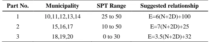
Ghanbari’s (2005) research explained that in southern parts of Tehran, there were three different types of soil. An approximate equation suggested that for each part, an elastic modulus should be calculated. Figure
3 shows the regions and approximate equation suggested for each area. In addition, Table 1 describes the SPT numbers of each region and suggests elastic modulus equations (Ghanbari, 2005).
Table 1. SPT numbers for each municipality region and suggested elastic modulus equations
Part No. Municipality SPT Range Suggested relationship
1 10,11,12,13,14 25 to 50 E=6(N+2D)+100
2 15,16,17 10 to 50 E=7(N+2D)+25
107
Fig. 3. Study area location and relevant equations for each part of the study area
MATERIALS & METHODS
Several methods exist in numerical analysis to account for fluid structure interaction (FSI). A fluid structure interaction (FSI) problem is generally defined as a problem where one or more deforming solids interact with an internal or surrounding fluid flow. Many different analytical and semi-analytical methods have been developed for liquid tank sloshing problems that can be used to verify and develop more advanced numerical methods. These methods are often limited to the analysis of tanks with simple geometries, such as rectangular or cylindrical tanks. The methods presented in this paper are the analytical methods developed by Westergaard (1931) and Faltinsen (1978), and the simplified approximate methods put forth by Housner (1963) and Epstein (1976).
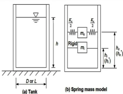
Fig. 4. Equivalent dynamic system for a water tank
(Housner, 1963)
108
is rigidly connected to the structure and a convective mass that is attached to the walls with a spring, as illustrated in Figure 4. The liquid in the lower region of the tank behaves like a mass that is rigidly connected to the tank wall. This mass is termed an impulsive liquid mass, which accelerates along with the wall and induces impulsive hydrodynamic pressure on the tank walls, and similarly, on its base. Liquid mass in the upper region of the tank undergoes sloshing motion. This mass is termed a convective liquid mass and exerts convective hydrodynamic pressure on the tank walls and its base. Thus, total liquid mass is divided into two parts in the spring
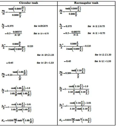
mass model of a tank-liquid system, i.e., impulsive mass and convective mass; these two liquid masses need to be suitably represented. The parameters of the spring mass model depend on tank geometry and were originally derived by Housner (1963). Expressions for these parameters are shown in Figure 5. It should also be noted that for certain values of H/D ratio, the sum of impulsive mass (mi) and convective
mass (mc) will not be equal to the total
mass (m) of liquid; however, the difference is usually negligible (2% to 3%).
This difference is attributed to assumptions and approximations made in the derivation of these quantities.
109
For a ground-supported tank, where walls are rigidly connected with the base slab, the time period of impulsive mode of vibration Ti, in seconds is given by
Equation 1 (Eurocode 8, 2003).
i i h p T C t E D (1)
where Ci is the coefficient of the time
period for impulsive mode, h is the maximum depth of liquid, D is the inner diameter of a circular tank, t is the thickness of the tank wall, E is the modulus of elasticity of the tank wall and ρ is the mass density of liquid. The coefficient Ci is
given by Equation 2.
2 1 0.46 0.3 ( ) 0.067( ) i C h h h D D D (2)
The expression for the impulsive mode period of the circular tank was taken from Eurocode 8 (2003). This expression was developed for roofless steel tanks fixed at the base and filled with water. However, this may also be used for other tank materials and fluids. For tanks resting on soft soil, the effect of the flexibility of the soil may be considered when evaluating the time period. Generally, soil flexibility does not affect the convective mode time period. However, soil flexibility may affect the impulsive mode time period. Soil structure interaction has two effects: firstly, it elongates the time period of the impulsive; secondly, it increases the total damping of the system (Eurocode 8, 2003).
In this paper, the authors discuss interaction problems related to structure-soil systems based on tanks placed on rigid foundations and homogeneous soils in southern parts of Tehran. Lateral and rocking vibrations were considered, as the effects of these motions are generally more important than vertical and torsion vibrations, which were neglected in this study. Interactions are represented by the
equivalent spring-mass system as proposed by Housner (1963) and soil-structure interactions are represented by equivalent springs, as suggested in FEMA 368/369 (2000). Kx and KƟ represent the equivalent
translational and rocking stiffness of the foundation that can be modelled with springs. The springs are attached to the central point of the rigid circular foundation. The stiffness of Kx and KƟ for
circular rigid foundations supported at the surface of a homogeneous half space was provided by Lysmer's theory as per Equations 3 and 4:
8 2 GR Kx (3) 3 8 3(1 ) GR K (4)
where R is the radius of the foundation, G is the shear modulus of the soil and Ʋ is the Poisson’s ratio for the soil. These stiffnesses were also estimated using the expressions given in FEMA for embedment and foundations that rest on a surface stratum of soil underlain by a stiffer deposit that has a shear wave velocity more than twice that of the surface layer. FEMA proposes a similar equation that can be written as shown in Equation 5.
2
1 (1 x )
x
K H K
T T
K K
(5)
110
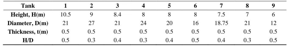
Table 2. Common sizes of ground-supported tanks and H/D ratios
Tank 1 2 3 4 5 6 7 8 9
Height, H(m) 10.5 9 8.4 8 8 8 7.5 7 6
Diameter, D(m) 21 27 21 24 20 16 18.75 21 12
Thickness, t(m) 0.5 0.5 0.5 0.5 0.5 0.5 0.5 0.5 0.5
H/D 0.5 0.3 0.4 0.3 0.4 0.5 0.4 0.3 0.5
RESULTS & DISCUSSION
Regarding the size of tanks in this study, the graphs in Figure 6 were plotted to
illustrate the different ratios of H/D and the different values of the Ci coefficient.
Fig. 6. Plots of the Ci coefficient and different H/D ratios
In addition, according to Equation 2, there were different parameters that affected the impulsive period. Additionally, the material of ground-supported tanks' walls such as concrete or steel, which had different elastic moduli, had different effects on the impulsive period. Figure 7 shows variations in impulsive period with constant material and thickness as a result of changing the mass density of liquid.
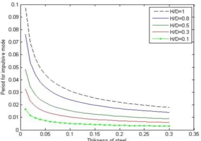
Variations in impulsive period for different H/D ratios and steel wall thicknesses of a ground-supported tank serving as a water reserve (P=1000kg/m3) with 10*10 structural height and width are shown in Figure 8. The results showed that the impulsive period in higher H/D ratios was higher than in lower ones and that thickness had a direct correlation with impulsive period.
If concrete is considered as the material of tank walls, Figure 9 shows the variations of impulsive period with a constant material and thickness. The results of liquids with different densities are also plotted.
111
Fig. 7. Variations in impulsive period with steel material (E=2*1011); upper band Thickness=0.1m (left), -
Thickness=0.15m (right); middle band Thickness=0.2m (left), - Thickness=0.25m (right); lower band
112
Fig. 8. Variations in impulsive period for a steel water tank
Fig. 9. Variations of impulsive period with concrete material (E=2.48*10^10); upper band Thickness=0.1m
(left) -Thickness=0.15m (right), middle band Thickness=0.2m (left) - Thickness=0.25m (right), lower band
113
Fig. 10. Variations within the impulsive period for a concrete water tank
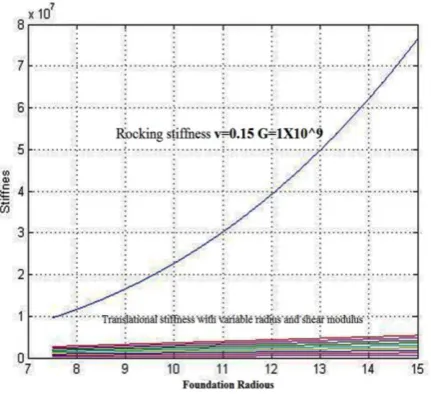
Kx and KƟ were translational and
rocking stiffness, respectively, of the foundation that was modelled with springs. Regarding translational stiffness equation, results showed that Poisson’s ratio had a negligible effect, while the shear modulus and radius of the tank foundation were
more influential. Furthermore, higher values of shear modulus and radius of foundation resulted in higher values of stiffness. Figure 11 shows different translational stiffness in the case of variable radius and shear modulus of the foundation soil.
Fig. 11. Translational stiffness with variable radius and shear modulus
Regarding the comparison of translational and rocking stiffness in Figure 12, results showed the lowest rocking stiffness of soft soil to be much greater than the maximum value of translational stiffness. Thus, the radius and shear
114
Figure 14 classifies the rocking stiffness values for southern parts of Tehran’s soil, with a constant shear modulus and different foundation radius and Poisson’s ratios.
According to the FEMA 368/369 equation shown in Figure 15, the maximum range of ~T/T ratio ranged from 3.2 to 3.6, with different Poisson’s ratio values and a
maximum value of K/Kx ratio.
Classification of ~T/T ratio with different shear moduli and Poisson’s ratios showed that K/Kx ratio was the most important
factor for increasing the ~T/T ratio. Furthermore, it was shown that there was no relationship between shear modulus and ~T/T ratio.
Fig. 12. Differences between translational and rocking stiffness values
Fig. 13. Variations of different foundational radius and rocking stiffness values
115
Fig. 15. ~T/T ratio classification using different K/Kx and Poisson's ratios
CONCLUSION
According to the results achieved in this paper, one of the most important factors for increasing or decreasing Ci coefficient is
H/D ratio. It was shown that from H/D=0.1 to 0.7, Ci was decreased and from H/D 0.7
to 2, it was increased. While Ci ratio is a
direct coefficient that impacts on the impulsive period, this factor is considered to be significant for impulsive period prediction. In addition, results showed that the liquid mass density effect on impulsive period is as low as the thickness of the ground-supported wall. Aside from this result, wall material is an important factor in the variation of impulsive period. Generally, concrete material will be more periodic than steel for different thicknesses and H/D ratios.
Regarding soil stiffness (translational and rocking), Poisson’s ratio had a negligible effect on translational stiffness, while its effect on rocking stiffness was significant. In addition, the rate of rocking
stiffness was higher than translational stiffness with a similar shear modulus and Poisson’s ratio. Results also showed that ~T/T ratios had no effect on shear modulus. Furthermore, the K/Kx ratio was considered the first effective parameter for changing ~T/T ratio, while Poisson’s ratio was regarded as the second most effective. Overall, in southern parts of Tehran, when the SSI method was chosen, the impulsive period was increased between 1 to 3.6 times greater than the normal impulsive period.
REFERENCES
Aslam, M. and Godden, W.G. (1979). Earthquake sloshing in annular and cylindrical Tanks. J. Eng. Mech., 105, 371-379.
AWWA M-42 Steel water storage tanks user guide (2013). American water works association. ISBN: 9781583219485.
Berberian, M. (1994). Natural Hazards and the First Earthquake Catalogue of Iran. International Institute
of Earthquake Engineering and Seismology
116 Chen, C.P. and Barber, R.B. (1976). Seismic design of liquid storage tanks to earthquakes. International Symposium on Earthquake Structural Engineering, St. Louis, MO., 2, 1231–1247.
Epstein, H.I. (1976). Seismic design of liquid storage tanks. J. Struct. Div., 102, 1659–1673.
Eurocode - 8. (2003). Design of structures for earthquake resistance,Part1, General rules Seismic action and general requirements for structures, Part 4, Silos, tanks and pipelines. European Committee for Standardization.
FEMA 368/369. (2000). The 2000 NEHRP Recommended Provisions for New Buildings and Other Structures, Part 1: Provision and Part 2: Commentary. Federal Emergency Management Agency, Washington.
Ghanbari, A. (2005). Assessment of southern part of Tehran alluvium elastic modulus. Journal of Earth Sciences. 71, 3- 8.
Goto, Y. and Shirasuna, T. (1980). Studies on Earthquake Response of Grouped Underground Tanks in Soft Ground. 7th World Conference on Earthquake Engineering, Istanbul. 173-180.
Housner, G. W. (1963). Dynamic behavior of water tanks. Bulletin of the Seismological Society of America. 53, 381-387.
Haroun, M.A. and Ellaithy, M.H. (1985).
Seismically induced fluid forces on elevated tanks.
J.Tech. Top. Civ., 111, 1–15.
Kianoush, M.R. and Chen, J.Z. (2006). Effect of vertical acceleration on response of concrete rectangular liquid storage tanks, Engineering Structures. 28(5), 704-715.
Larkin, T. (2008). Seismic response of liquid
storage tanks incorporating soil structure
interaction. J. Geotech. Geoenviron., 134(12), 1804-1814.
Livaoglu, R. (2008) Investigation of seismic behavior of fluid–rectangular tank –soil/foundation systems in frequency domain. Soil Dyn. Earthq. Eng., 28(2), 132–146.
Naderi, R., Yosefi Samangany, A. and Talebpour, M.H. (2013). Effect of type of earthquake seismic analysis of concrete cubed shaped tanks buried according to the interaction of soil structure. 5th
Symposium On Advanced in Science &
Technology, Khavaran Higher-education Institute, Mashhad, Iran.
Nasrabadi, T. and Abbasi Maedeh, P. (2014). Groundwater quality assessment in southern parts of Tehran plain, Iran. Environ. Earth Sci., 71, 2077– 2086.
Nasrabadi, T., Hoveidi, H., Nabi Bidhendi, G.R., Yavari, A.R. and Mohammadnejad, S. (2008). Evaluating citizen attitudes and participation in solid waste management in Tehran, Iran. J. Environ. Health, 71(5), 30–33.
NZS. (2004). Structural Design Actions, Part 5: Earthquake actions New Zealand standard.
NZSEE. (2009). Seismic design of storage tanks - Recommendations of a study group of the New
Zealand national society for earthquake
engineering.
Oyarzo-Vera, C., McVerry, G. and Ingham, J. (2012). Seismic zonation and default suite of ground-motion records for time-history analysis in the North Island of New Zealand. Earthquake Spectra. 28, 667-688.
Rai, D.C. (2002). Seismic retrofitting of R/C shaft support of elevated tanks. Earthquake Spectra. 18, 745–760.
Taniguchi, T. (2004). Rocking behavior of unanchored flat-bottom cylindrical shell tanks under action of horizontal base excitation. Eng. Struct., 26, 415–426.
Veletsos, A. S. and Meek, J. (1974). Dynamic
behavior of building-foundation systems.
Earthquake Eng. Struc., 3, 121-138.
Veletsos, A. S. and Tang, Y. (1990). Soil structure interaction effects laterally excited liquid storage tanks. Earthquake Eng. Struc., 19, 473-496.
Youssef, A. (1998). Seismic response of inelastic
structures on compliant foundations. Ph.D.
Dissertation. Department of Civil and Environmental Engineering, Northeastern University Boston, MA, USA.