THERMAL ANALYSIS OF LASER HARDENING FOR
DIFFERENT MOVING PATTERNS
G.H. Farrahi* and M. Sistaninia
School of Mechanical Engineering, Sharif University of Technology P.O. Box 11365-8639, Tehran, Iran
[email protected] - [email protected]
*Corresponding Author
(Received: October 9, 2007 – Accepted in Revised Form: February 19, 2009)
Abstract Transient thermal field in laser surface hardening treatment of medium carbon steel was analyzed by employing both three-dimensional analytical model and finite element model. In finite element model the laser beam was considered as a moving plane heat flux to establish the temperature rise distribution in the work-piece, while in analytical model laser beam was considered as an internal heat source. The numerical results were compared with the analytical results. In laser heat treatment of steel some methods are used to produce a wider and nearly uniform average irradiance profile. It may be achieved by rotating the beam optically, thereby producing an overlapping spiral track, or by dithering the beam (rocking the lens or mirror) perpendicular to the track, thus producing a zigzag pattern. In this paper, these models are used to cover the two mentioned patterns for laser hardening with Gaussian distribution, and to compare the results with the hardened region of bimodal and uniform distribution. The results show that dithering beam and rotating beam are useful for obtaining a uniform heat intensity distribution, if the parameters of dithering beam or rotating beam are properly chosen with the aid of these models. The diffusion process being a time dependent phenomenon, an interaction time of 15 ms was taken as a basis to determine the hardened region.
Keywords Laser, Thermal Analysis, Heat Treatment, Surface Hardening, Finite Element Model, Dithering Beam, Rotating Beam
ﻩﺪﻴﻜﭼ
ﺣﻱﺎﻣﺩﻥﺍﺪﻴﻣ ﻴ
ﻠﻤﻋﻦ ﻴ ﺖﺨﺳﺕﺎ ﻂﺳﻮﺘﻣﻦﺑﺮﮐﺎﺑﺩﻻﻮﻓﮏﻳﻲﺤﻄﺳﻥﺩﺮﮐ
، ﻪﺑﻢﻫ ﻭﺩﻭﺪﺤﻣﻥﺎﻤﻟﺍﺵﻭﺭ
ﻪﺑﻢﻫ ﻠﺤﺗﺵﻭﺭ ﻴﻠ ﻲ ﺖﺳﺍ ﻩﺪﺷﺰﻴﻟﺎﻧﺁ
.
ﻪﺑ ﺭﺰﻴﻟﺩﻭﺪﺤﻣﻥﺎﻤﻟﺍ ﻝﺪﻣﺭﺩ ﻩﺪﺷﻝﺪﻣ ﮎﺮﺤﺘﻣﻲﺗﺭﺍﺮﺣﺭﺎﺷ ﮏﻳﻥﺍﻮﻨﻋ
ﺖﺳﺍ ، ﺭﺩ ﻟﺎﺣ ﻲ ﻪﺑﺭﺰﻴﻟﻲﻠﻴﻠﺤﺗﻝﺪﻣﺭﺩﻪﮐ ﺭﺩﻱﮊﺮﻧﺍﺪﻴﻟﻮﺗﻊﺒﻨﻣﮏﻳﺕﺭﻮﺻ
ﺩﺰﻧ ﺭﺩﻭﻪﻌﻄﻗﻞﺧﺍﺩ ﻳ
ﮑ ﻲ ﻥﺁﺢﻄﺳ
ﺖﺳﺍﻩﺪﺷﻝﺪﻣ
.
ﻪﺑ ﺭﻮﻃ ﺖﺨﺳﺕﺎﻴﻠﻤﻋﺭﺩﻲﻠﮐ ﻪﺑﻲﻳﺎﻫﺪﻨﻓﺮﺗﺭﺰﻴﻟﺎﺑﻲﺤﻄﺳﻥﺩﺮﮐ
ﻲﻣﺭﺎﮐ ﺩﻭﺭ ﻊﻳﺯﻮﺗﺎﺑﺭﺰﻴﻟﺯﺍﻪﮐ
ﺾﻳﺮﻋﻭﺖﺧﺍﻮﻨﮑﻳ ﺩﻮﺷ ﻩﺩﺎﻔﺘﺳﺍ ﺮﺗ
.
ﻳ ﮑ ﻲ ﻩﺍﺭ ﺯﺍ ﺎﻫ ﻱ ﺖﺳﺩ ﻳ ﺍﻪﺑ ﻦﺘﻓﺎ ﻳ ﻢﻬﻣﻦ ﻩﺩﺎﻔﺘﺳﺍ ﻲﺸﺧﺮﭼﺎﻳﻥﺍﺯﺮﻟ ﻮﺗﺮﭘﺯﺍ
ﺖﺳﺍ ؛ ﻪﺑ ﻪﻧﻮﮔ ﻭﺭﺎﺟﺚﻋﺎﺑ ﻪﮐﻱﺍ ﺭﺰﻴﻟ ﺖﮐﺮﺣﺮﻴﺴﻣ ﻥﺪﺷ
ﺩﻮﺷ
.
ﻝﺪﻣﺯﺍﻩﮊﻭﺮﭘ ﻦﻳﺍ ﺭﺩ ﺮﮐﺫ ﻱﺎﻫ
ﺰﻴﻟﺎﻧﺁ ﻱﺍﺮﺑﻩﺪﺷ
ﻲﺷﺎﻧ ﻱﺎﻣﺩ ﻥﺍﺪﻴﻣ ﻴﺣﺎﻧ ﺎﺑ ﻭ ﺖﺳﺍ ﻩﺪﺷ ﻩﺩﺎﻔﺘﺳﺍ ﺎﻫﻮﮕﻟﺍ ﻦﻳﺍ ﺯﺍ
ﺔ ﺖﺨﺳ ﻲﺷﺎﻧ ﻩﺪﺷ ﻊﻳﺯﻮﺗ ﺯﺍ
،ﻝﺍﺪﻤﻴﺑ ﻱﮊﺮﻧﺍ ﻱﺎﻫ
ﺖﺳﺍ ﻩﺪﺷﻪﺴﻳﺎﻘﻣ ﻦﻴﺳﻮﮔ ﻭﺖﺧﺍﻮﻨﮑﻳ
.
ﺎﺘﻧ ﻳ ﻥﺎﺸﻧﺞ ﯽﻣ ﺪﻫﺩ ﻩﺩﺎﻔﺘﺳﺍ ﺸﺧﺮﭼﻭﻥﺍﺯﺮﻟﻮﺗﺮﭘ ﺯﺍ ﻲ
، ﺷﻭﺭ ﻲ ﻨﻣﺩﻮﺳ ﺪ
ﺍﺮﺑ ﻱ ﺑ ﻪ ﺯﻮﺗﻥﺩﺭﻭﺁﺖﺳﺩ ﻳ
ﺕﺭﺍﺮﺣﻊ ﻳ
ﺖﺳﺍﺖﺧﺍﻮﻨﮑ ؛
ﻪﺑ ﻃﺮﺷ ﻲ ﺎﻫﺮﺘﻣﺍﺭﺎﭘﻪﮐ ﻱ
ﺸﺧﺮﭼﻮﺗﺮﭘ ﻲ
ﻳ ﺎﺑﻥﺍﺯﺮﻟﺎ ﻩﺩﺎﻔﺘﺳﺍ
ﺍﺯﺍ ﻳ ﻦ ﻝﺪﻣ ﺯﺎﺳ ﻱ ﺑﻮﺧﻪﺑﺎﻫ ﻲ ﺪﻧﻮﺷﺏﺎﺨﺘﻧﺍ
.
ﻮﻔﻧﺪﻨﻳﺍﺮﻓ ﺫ ﺎﻣﺯﺪﻨﻳﺁﺮﻓﮏﻳ ﺮﺒﻧ
ﺖﺳﺍ ؛ ﺶﻨﮐﺭﺪﻧﺍﻥﺎﻣﺯﻞﻴﻟﺩﻦﻴﻤﻫﻪﺑ ۱۵
ﻲﻠﻴﻣ ﻪﻴﻧﺎﺛ ﻴﺣﺎﻧﻦﻴﻴﻌﺗﻱﺍﺮﺑ ﺔ
ﺖﺨﺳ ﺭﺩﻩﺪﺷ ﺪﺷﻪﺘﻓﺮﮔﺮﻈﻧ ﺳﺍﻩ
ﺖ
.
1. INTRODUCTION
In laser surface hardening, the work-piece is heated on surface by a laser beam. The laser travels from one end of the work-piece to the other end. In order to achieve the phase transformation, the temperature in the hardening zone, should be greater than the phase change temperature (Tphase). However, the temperature should not exceed the
melting temperature and should be high and long for the austenitic transformation of steel to take place. In order to activate phase change, the cooling rate should also be greater than the critical cooling rate. The high cooling rate of the work-piece is achieved by the speed of the torch and the heat loss from the work-piece.
beam spot) with a uniform heat intensity distribution, in order to attain a more uniform case depth [1]. This can be accomplished by the following three approaches:
The first one is achieved by rotating the beam optically, thereby producing an overlapping spiral track, or by dithering the beam (rocking the lens or mirror) perpendicular to the track, thus producing a zigzag pattern. Figure 1 is an illustration of these techniques. The second alternative involves the use of a bimodal (TEM11) shaped laser beam. Unfortunately, it is difficult to maintain a high-quality, high-order mode over a long period of time; also the beam may not be symmetrical which complicates matters if contour tracks are required. The third alternative involves the use of not-so-sharp focused high-peak power, low order (TEM00) mode Gaussian laser beam [2].
Modeling the thermal field due to laser hardening has been subject to many researches. Most of these works were carried out on quasi-steady state, [3-8]. In the past decade, Rajadhyaksha, et al [8] solved conductive heat transfer under steady-state condition, with a finite element model. The systematic approach was applied to optimize the laser surfacing process. They compared their results with a Lagrangian formulation. They also computed design sensitivities of the temperature field using both the direct differentiation and the adjoint methods.
There are also a few works that developed a transient model to model the thermal field in laser
hardening [9-13]. In recent years Komanduri, et al [9] has carried out comprehensive investigations on the thermal field under transient condition. They developed a 3D analytical model using a circular moving heat source with Gaussian, bimodal and uniform distributions. They applied the results of their analytical model to optimize the laser hardening process parameters for AISI 1036 (EN8) steel. The interaction time of 15 ms was taken as the basis to predict hardened region.
In previous works [3-13] the thermal field in laser hardening with uniform traverse velocity along a straight line has been investigated. However, for laser hardening with rotating or dithering even if the heat flux is fixed in space and the material move (Eulerian formulation) the thermal field remains transient and never reduce to a steady-state then thermal modeling of laser hardening with rotating and dithering beam needs a transient formulation. In the present study, the laser beam is regarded as a moving heat source with heat intensity distribution namely, Gaussian, bimodal, or uniform and various moving patterns (beam rotating and beam dithering).
2. ANALITICAL MODEL
An analytical model, based on the well-known transient heat conduction equation was adopted to describe the time and space temperature distribution T(r,t) in the material under the action of a laser beam that may dithering or rotating:
) t , r ( f ) T K ( t T p
c +∇− ∇ =
∂ ∂
ρ (1)
Where cp, ρ and K denote, respectively, the specific heat, density and thermal conductivity of the work-piece and the heat source term f(r,t), at the right side of Equation 1, is identified as the heat distribution of the laser beam.
If ρ, cp and K are temperature independent, Equation 1 is reduced to:
K ) t , r ( f T 2 t T 1
= ∇ − ∂ ∂
α (2)
Where α = K/ρ cp is the thermal diffusivity.
In the case of three-dimensional transient,
non-homogeneous heat conduction problem given by Equation 2, the solution for T(r,t) is expressed in terms of the three-dimensional Green’s function, [14]
,
RG(r,t|r,' )| 0 F( 'r)d '
RG(r,t|r,' )f(r,' )d ' t 0 d K ) t , r ( T
∫ τ τ= ν
+
∫ τ τ ν
∫ =τ τ κ
=
(3)
Where F( 'r) is the initial temperature distribution. The three-dimensional Green’s function can be obtained from the product of the three one-dimensional Green’s function as in rectangular coordinates: , ) ,' z | t , z ( 3 G ) ,' y | t , y ( 2 G ) ,' x | t , x ( 1 G ) ,' z ,' y ,' x | t , z , y , x ( G τ × τ × τ = τ (4)
Where each of the one-dimensional Green’s functions G1, G2 and G3 depends on the extent of the region (i.e., finite, semi infinite, or infinite) and the boundary conditions, where the infinite medium Green’s function is obtained as [14]:
⎟ ⎟ ⎠ ⎞ ⎜ ⎜ ⎝ ⎛ τ − α − − − τ − πα = τ ) t ( 4 2 ) ' x x ( exp 2 / 1 )] t ( 4 [ ) ,' x | t , x (
G (5)
and the semi infinite medium Green’s function when the boundary at z' = 0 is of the second kind (insulate) is obtained as:
, ) t ( 4 2 ) ' z z ( exp ) t ( 4 2 ) ' z z ( exp 2 / 1 )] t ( 4 [ ) ,' z | t , z ( G ⎥ ⎥ ⎦ ⎤ ⎢ ⎢ ⎣ ⎡ ⎟ ⎟ ⎠ ⎞ ⎜ ⎜ ⎝ ⎛ τ − α + − + ⎟ ⎟ ⎠ ⎞ ⎜ ⎜ ⎝ ⎛ τ − α − − × − τ − πα = τ (6)
Substituting G1 (x,t|x΄,τ), G2 (y,t|y΄,τ) from Equation 5 and G3 (z,t|z΄,τ) from Equation 6, in Equation 4 yields the three-dimensional Green’s function, for z' = 0 (on z' = 0, f (r΄,τ) ≠ 0 otherwise, f (r΄,τ) = 0), as
⎟ ⎟ ⎠ ⎞ ⎜ ⎜ ⎝ ⎛ τ − α + − + − − × − τ − πα = τ = ) t ( 4 2 z 2 ) ' y y ( 2 ) ' x x ( exp 5 . 1 )] t ( 4 [ 2 ) , 0 ' z ,' y ,' x | t , z , y , x ( G (7)
With the substitutions x΄ = x – r cos θ, y΄ = y – r sin θ and G (r,t|r΄,τ) from Equation 7, in Equation 3 the temperature distribution is obtained as,
τ θ τ − α + − × − τ − πα × τ θ − θ − ∫ ∫ππ− ∫∞ α + = d d dr r ] ) ) t ( 4 2 z 2 r ( exp 5 . 1 )] t ( 4 [ ) , sin r y , cos r x ( f t
0 0 [
K 2 o T ) t , z , y , x ( T (8)
In this equation, f(x-rcosθ, y-rsinθ, τ) is the beam intensity distribution, which for a beam with Gaussian distribution that moves along a straight line is obtained as:
⎪⎭ ⎪ ⎬ ⎫ ⎪⎩ ⎪ ⎨ ⎧ ⎟ ⎟ ⎟ ⎠ ⎞ ⎜ ⎜ ⎜ ⎝ ⎛ θ − + τ − θ − − − × π = τ θ − θ − 2 o r 2 ) sin r y ( 2 ) v cos r x ( 3 exp 2 o r Q 3 ) , sin r y , cos r x ( f (9)
Where ro is the characteristic (beam) radius (defined as the radius at which the intensity of the laser beam falls to 5 % of the maximum intensity) and Q is the power transferred into the substrate (equal to
P
A× , where A is the absorptivity and P is the laser power) [16], ν is the laser velocity along moving line (longitudinal velocity).
For a dithering beam f(x-rcosθ,y-rsinθ,τ) is obtained as: , } 2 o r ) 2 )) * / 2 cos( max l sin r y ( 2 ) v cos r x ( ( 3 { exp 2 o r Q 3 ) , sin r y , cos r x ( f τ πτ − θ − + τ − θ − − π = τ θ − θ − (10) Where lmax is the amplitude and τ* is the period of
every cycle.
For a rotating beam the beam intensity distribution is obtained as:
} 2 o r ) 2 )) * / 2 cos( max l sin r y ( 2 )) * / 2 sin( a v cos r x ( 3 { 2 o r Q 3 ) , sin r y , cos r x ( f τ πτ − θ − + τ πτ − τ − θ − − × π = τ θ − θ −
exp (11)
moving line and it should be chosen so that covers the area as best as possible while the maximum temperature become minimum. The best choice for ‘a’ is half of distance that laser in every period transfer (i.e. a=ντ*/2).
For a dithering beam with uniform velocity in every half of cycle f(x-rcosθ,y-rsinθ,τ) change and is obtained as,
⎪ ⎪ ⎪ ⎪ ⎪ ⎪ ⎪ ⎪ ⎩ ⎪⎪ ⎪ ⎪ ⎪ ⎪ ⎪ ⎪ ⎨ ⎧ + < ≤ + ⎪ ⎪ ⎭ ⎪ ⎪ ⎬ ⎫ ⎪ ⎪ ⎩ ⎪ ⎪ ⎨ ⎧ − × + − + θ − + τ − θ − − × π + < ≤ × ⎪ ⎪ ⎭ ⎪ ⎪ ⎬ ⎫ ⎪ ⎪ ⎩ ⎪ ⎪ ⎨ ⎧ + × − − θ − + τ − θ − − × π = τ θ − θ − * r ) 1 n ( r * r ) 5 . 0 n ( , 2 o r ) 2 ) max l ) * r ) 5 . 0 n ( r ( * v sin r y ( 2 ) v cos r x (( 3 xp 2 o r Q 3 * r ) 5 . 0 n ( r * r n , 2 o r ) 2 ) max l ) * r n r ( * v sin r y ( 2 ) v cos r x (( 3 xp 2 o r Q 3 ) , sin r y , cos r x ( f e e (12)
Where νis the laser velocity component along the moving line (longitudinal velocity) and ν* is the laser velocity component across the moving line. Similarly for other distribution f(x,'y,'τ)could be obtained. For example for bimodal distribution that moves along a straight line f(x-rcosθ,y-rsinθ,τ) is obtained as:
⎥ ⎥ ⎥ ⎥ ⎥ ⎥ ⎥ ⎥ ⎦ ⎤ ⎢ ⎢ ⎢ ⎢ ⎢ ⎢ ⎢ ⎢ ⎣ ⎡ + θ − + τ − θ − − + − θ − + τ − θ − − × π = τ θ − θ − 2 ) 947 . 0 o r 2 ) sin r y ( 2 ) v cos r x ( 947 . 3 ( e 2 ) 947 . 0 o r 2 ) sin r y ( 2 ) v cos r x ( 947 . 3 ( e 2 o r Q 3677 . 4 ) , sin r y , cos r x ( f (13)
3. FINITE ELEMENT MODEL
The basic heat-transfer equations considered are:
F = ∇(-KT) (14a)
Which relates the heat flux F to thermal gradient:
G t T p c ) T K ( =− ∂ ∂ ρ − ∇
∇ (14b)
Which applies to nonsteady-state heat conduction, where again ρ is the density, cp the specific heat, T the temperature, t the time, K the thermal conductivity and G the internal generation of heat. G is zero where the incident laser power is modeled as a heat flux.
In this model we divide the time during laser beam continuous irradiation to n time increment Δt, during every increment Δt we assume that laser beam don’t move and the program determine thermal load for every node on the heated surface, that depend on the laser beam position, heat intensity distribution and the node position. Laser beam position depends on the moving pattern, speed and time, thus the value of thermal load for every node on the heated surface is a function of time and place.
Care must be taken, however, in the determination of heat flux for every node if the incident intensity is discontinuous, as would be the case for the uniform disk beam mode intensity (called top hat) distribution, ⎪⎩ ⎪ ⎨ ⎧ < + π = . Otherwise 0 o r 2 y 2 x 2 o r / Q ) y , x (
q (15)
In every time increment finite element code is used to compute the solution to the heat transfer Equation 14 and the result of every time increment becomes the initial condition of next time increment. For small Δt we can assume that the laser moves continuously.
In the model, it is necessary to make a decision about the element size and shape, time increment and number of step n* for every time increment. Since these quantities are not independent, the following relation can be written:
⎪ ⎪ ⎩ ⎪ ⎪ ⎨ ⎧ Δ = Δ Δ α Δ = * n t * t * t 2 x o F (16)
thermo-diffused efficiencyα, time step Δt* and node spacing Δx, should be below 2 [13]. This decision has been made with the help of the analytical model.
In finite element model, the Gaussian distribution q(r) can be expressed as [15]:
⎪ ⎭ ⎪ ⎬ ⎫
⎪ ⎩ ⎪ ⎨ ⎧
⎟ ⎟ ⎠ ⎞ ⎜ ⎜ ⎝ ⎛ − π
=
2
o r
r 3 exp 2 o r Q 3 ) r (
q (17)
Where (as mentioned) ro is the characteristic radius and Q is the power transferred into the substrate. The heat flux of the square beam mode can be expressed as follows [16]:
⎪ ⎪ ⎩ ⎪ ⎪ ⎨ ⎧
< < − <
< − =
. Otherwise 0
22 d y 22 d and 21 d x 21 d
2 d 1 d
Q
) y , x ( q
(18)
Where d1 and d2 are the beam width and length, respectively. For a bimodal distribution on a circular disc heat source; the heat release intensity q(r) is a function of r. In bimodal distribution which the distance from the center of the distribution curve to one of its peaks on the ri-axis is 0.24 ro can be expressed by the following equation [9]:
] 2 ) 947 . 0 ) o r / r ( 947 . 3 ( e
2 ) 947 . 0 ) o r / r ( 947 . 3 ( e [ 2 o r Q 3677 . 4 ) r ( q
+ −
+ −
− π =
(19)
4. EXAMPLE PROBLEM
The models, developed in the previous sections, are exemplified in the analysis and optimization of the laser surface-hardening process of a gear tooth. We adopted the same example (Figurer 2) used by Komanduri, et al [9]. In their work the laser beam traverses longitudinally along the work surface (x-axis) at a longitudinal velocity of Vsc followed by an appropriate transverses feed, f along the y-axis,
while in our case the laser beam may rotate or dithering during this process.
For laser hardening with dithering or rotating beam, the cross feed changes from one point to another point longitudinally along the work surface (x-axis) and depends on the condition that the point is located relative to the path of moving laser. For this reason, we determine maximum and minimum cross feed for every case. Maximum cross feed usually occurs on the cross section between two sequences peak, although its temperature is less than the temperature of points on the center line of every peak. However, it requires the time necessary for the phase transition.
4.1. System Characteristics
The dimensions of gear tooth used are shown in Figure 2, but only a 10mm layer from heated surface are considered in order to reduce calculation time. The gear is made of steel AISI 1036. The thickness of the hardening layer is taken as 0.12 mm. The phase transition temperature for the AISI 1036 steel is taken as 775˚C and the melting temperature as 1470˚C [9,17] and a critical martensite temperature of 430˚C [18]. In order to obtain martensite, the martensizing temperature should be reached in less than 3.5s from the austenizing temperature. Hence the critical cooling rate to achieve martensite is 91.43˚C/s [8]. The density of AISI 1036 is taken as7844 (kg/m3). The material has non-linear conductivity K and specific heat Cp, since these material properties depend on temperature. Temperature dependence of the thermo-physical properties of the work-piece is shown in Figure 3 [19]. The convection coefficients are also temperature dependent [8 and 20].
The laser beam which is used has an energy, power of 480 W and absorptivity of A = 71 %. The Table 1 shows the size of laser beams employed for the above mentioned cases.
5. RESULTS AND DISCUSSION
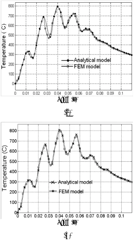
The effect of element size and time stepping and number of sub-steps for every load step in finite element model were studied with the help of the analytical model and for uniform thermal properties (uniform thermal properties of AISI 1036 at 25˚C). Figure 4 shows a comparison between FEM and analytical results. This figure shows the temperature changes with time for a point at x = 0.957mm, y = 0.565 mm and z = 0.118 mm in laser hardening with Gaussian distribution; amplitude lmax = 1 mm, period τ* = 0.015 s, longitudinal velocitiy 30 mm/s. and, (a) dithering beam with sinusoidal moving, (b) rotating beam. In this comparison the model has been discretized (discretization concerns the process of transferring continuous models and equations into discrete counterparts for numerical evaluation and implementation) by 4-node tetrahedral element. In order to reduce calculation and improve efficiency, dense meshes are used around the heated region. Because of small ∆t every load step solved by one sub-step (∆t*=∆t). The distance between nodes on the heated surface and around the heated region is 0.09 mm, thus the mesh under the laser is such that it has sufficient number of elements to capture the inflection of the Gaussian distribution, and for every cycle 10 load steps were used. As it is obvious we found a good agreement between FEM results and analytical results for these parameters (∆x,∆t) of the finite element model. In this investigation we found, for this case if the distance between nodes on the heated surface and around the heated region increase to 0.25 mm about 5 percent error could be found, and if the distances between nodes on the heated surface increase to 0.5 mm, about 16 percent
Temperature (˚C)
(a)
Temperature (˚C)
(b)
Figure 3. Thermal properties of AISI 1036 versus temperature [19]: (a) thermal conductivity of AISI 1036 versus temperature and (b) heat capacity of AISI 1036 versus temperature.
TABLE 1. Beam size Were used in this Study.
Intensity Distribution Beam Size Gaussian Disc Beam Mode 3 and 4 mm Diameter
Bimodal 5 and 4 mm
Diameter Uniform Square Beam Mode 2
×
2 mm Top-Hat Distribution Diameter 2.5 mm Rotating and Dithering Beamerror could be found. Although the time of one cycle or rotate is so small (0.1 s.), but at least 6 load step for every cycle are needed and if the number of load steps for every cycle increases more than 12 load steps the error does not considerably decrease. After an appropriate finite element model was found realistic temperature-dependent thermal properties, thermal conductivity and specific heat are included in the model and the cross feed for the case of no surface melting and 0.12 mm hardening depth is calculated. To compare the hardened region of rotating Gaussian beam and dithering
Gaussian beam with the hardened region of other intensity distributions (Gaussian, bimodal, uniform square and uniform disc mode), the cross feed of these distributions (with linear moving) are also studied.
Since diffusion during the heat treatment (surface transformation hardening) process is a time dependent phenomenon, an interaction time was taken as a basis to determine the hardened region. The time required for the phase transition of AISI 1036 steel corresponds to 0.015 s [3 and 9].
5.1. Cross Feed for Various Laser Beam
Intensity Distributions
Figure 5 shows the changes of the cross feed (for hardened depth of 0.12 mm) with the longitudinal velocity, respectively, for different laser beam intensity distributions (a) bimodal, (b) uniform and (c) Gaussian.It can be seen from Figure 5 that as the longitudinal velocity decreases the maximum temperature and cross feed increases until the maximum temperature reaches the melting temperature which is normally undesirable during hardening. As you see in this figure the maximum cross feed which could be obtained by this laser (power of 480 W) and these intensity distributions is associated with the uniform disc beam mode with 2.5 mm diameter and about 30mm/s. longitudinal velocity. It can be seen from Figure 5c that the maximum cross feed which could be obtained by this laser and with Gaussian distribution of heat intensity and with laser beam diameter of 3 mm which move along a straight line is about 0.8mm.
5.2. Cross Feed for Laser Hardening with
Rotating and Dithering Beam
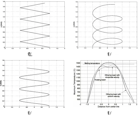
Figure 6 shows the variations of the maximum temperature rise in a section on the heated surface with distance from the center line, y, for different moving patterns (amplitude lmax = 1mm and period τ* = 0.015 s., longitudinal velocities 30 mm/s.). For laser hardening with dithering beam for uniform velocity, the maximum temperature occurs on the center line, and as the distance increases from the center line, the temperature decreases quickly, and as a result of that the hardened depth varies across hardened region and cross feed is lower than dithering beam with sinusoidal velocity, and also maximum temperature is high so surface melting could occur. Therefore velocity should change to produce a Time (s)(a)
Time (s)
(b)
uniform hardened depth across the hardened region. Thus in the following we only consider the dithering beam with sinusoidal scanning velocity.
As Figure 6d shows, the maximum temperature for rotating beam takes place where the longitudinal
velocity become zero instantly, Because of that temperature profile and hardened region aren’t symmetrical at two side of the center line.
In the following the effects of period, amplitude and longitudinal velocity on maximum and minimum cross feed are investigated. Longitudinal velocity is the component of the velocity along the heated surface (x-axis).
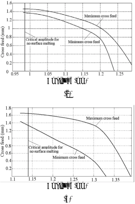
5.2.1. Cross feed for laser hardening with dithering beam Figure 7 shows the changes of maximum and minimum cross feed with amplitude, for longitudinal velocities 0f 30 mm/s., and periods of (a) 0.015 (b) 0.018 (C) 0.025.
It can be seen from Figure 7 that as the amplitude decreases the maximum temperature and cross feed increases until the maximum temperature reaches the melting temperature but the difference between maximum and minimum cross feed decreases.
It can also be seen that for a given period the cross feed f decreases and approaches zero after a certain amplitude level, depending on the longitudinal velocity and the required depth of hardening. This can be due to the high velocity which causes temperature decrease and to the fact that the interaction time is not enough for austenitizing. As the period increases, the maximum temperature, maximum cross feed and also the difference between maximum and minimum cross feed and the critical amplitude for no surface melting increases.
Figure 8 shows the variations of the cross feed with longitudinal velocity, for period of 0.015 s. and amplitudes of (a) 1mm (b) 1.2 mm, respectively. It can be seen from Figure 8 that as the velocity decreases the difference between maximum and minimum cross feed decreases. Also the maximum temperature and cross feed increases until the maximum temperature reaches the melting temperature.
It can be seen from Figures 7 and 8 that the maximum cross feed which could be obtained by this laser and with dithering Gaussian beam is associated with the process variables of period 0.015 s. amplitudes 1.2 mm and longitudinal velocity of about 20 mm/s. The value of this cross feed is about 2.5 times the maximum cross feed of linear moving (Figure 5c) and is slightly more than the maximum cross which could be obtained by the Velocity (mm/s)
(a)
Velocity (mm/s)
(b)
Velocity (mm/s)
(c)
uniform disc beam mode. But notice that the maximum cross feed of uniform disc beam mode is obtained with 30 mm/s. longitudinal velocity, whereas the maximum cross feed of dithering beam is obtained with 20 mm/s. longitudinal velocity. Longitudinal velocity is an important parameter in laser heat treatment, because it deals with the time duration of laser was hardening and so the energy which consumes during laser hardening. As you see in Figure 7, the maximum cross feed which could be obtained with dithering beam and with 30 mm/s.
longitudinal velocity is marginally less than the maximum cross feed of uniform disc beam mode.
5.2.2. Cross feed for laser hardening with rotating beam Figure 9 shows the variation of the maximum and minimum cross feed with amplitude for longitudinal velocities 0f 30 mm/s., and periods of (a) 0.015 (b) 0.025. It can be seen that as the amplitudes decreases, the maximum temperature and cross feed increases until the maximum temperature reaches the melting temperature. As
(a) (b)
(c) (d)
Figure 6. (a) dithering beam with uniform velocity (b) rotating beam pattern (c) dithering beam with sinusoidal velocity and (d) Variations of the maximum temperature rise in a section
you see a similar trend of dithering beam is observed for rotating beam except that in similar case the maximum temperature in rotating beam is
usually more than maximum temperature in dithering beam so the critical amplitude for no surface melting is more than the amplitude for no surface melting in dithering beam, and also the difference between maximum and minimum cross feed is more than the difference between maximum and minimum cross feed in dithering beam and temperature profile and hardened region aren’t symmetrical at two side of the center line.
6. CONCLUSIONS
From thermal analysis of laser surface transformation hardening process conducted on a work-piece made of AISI 1036 steel, the effect of moving parameters (scanning velocity, amplitude and period) on cross Amplitude (mm)
(a)
Amplitude (mm)
(b)
Amplitude (mm)
(c)
Figure 7. Variations of cross feed with amplitude for dithering Gaussian beam, respectively, for periods of (a) 0.015 s. and (b) 0.025 s.
Velocity (mm/s)
(a)
Velocity (mm/s)
(b)
feed for no surface melting and case hardening depth of 0.12 mm was studied. From this work the following conclusions can be made:
1. Dithering or rotating beam is a useful way of spreading out a uniform laser beam if the parameters of dithering beam or rotating beam are properly chosen with the aid of these models.
2. Dithering beam with sinusoidal scanning velocity results in a more uniform hardened region along the work surface (x-axis), compared to rotating beam with a lower maximum temperature.
3. As the period increases the maximum temperature and maximum cross feed increases and also the difference between maximum and minimum cross feed increases.
Similar effect takes place when longitudinal velocity decreases, although the difference between maximum and minimum cross feed decreases.
4. For a given period the cross feed f decreases and approaches zero after a certain amplitude level, depending the longitudinal velocities and the required depth of hardening. This can be due to the high velocity which causes temperature decrease and the fact that the interaction time is not enough for austenitizing.
7. REFERENCES
1. Mazumder, J., “Laser Heat Treatment: the State of the Art”, J. Metals, (May 1983), 18-26.
2. Luxon, J., “Laser-Industrial Applications”, Printice Hall, New Jersey, U.S.A., (1984), 223-224.
3. Cline, H.E. and Anthony, T.R., “Treating and Melting Material with a Scanning Laser or Electron Beam”, J. Appl. Phys., Vol. 48, No. 9, (1997), 3895-3900.
4. Mazumder, J. and Steen, W.M., “Heat Transfer Model for CW Laser Material Processing”, J. Appl. Phys., Vol.
51, No. 2, (1980), 941-947.
5. Sanders, D.J., “Temperature Distribution Produced by Scanning Gaussian Laser Beams”, Appl. Optics, Vol. 23, No. 1, (1984), 30-35.
6. Lax, M., “Temperature Rise Induced by a Laser Beam”,
J. Appl. Phys., Vol. 48, No. 9, (1977), 3919–3924.
7. Ohmura, E., Takamachi, Y. and Inoue, K., “Theoretical Analysis of Laser Transformation Hardening Process of Hypoeutectoid Steel Based on Kinetics”, Transactions of Japan Society of Mechanical Engineers, Vol. 56
(Series A), (1990), 1496-1503.
8. Rajadhyaksha S.M. and Michaleris, P., “Optimization of Thermal Processes Using an Eulerian Formulation and Application in Laser Surface Hardening”, Int. J. Numer. Meth. Eng., Vol. 47, (2000), 1807-1823.
9. Komanduri, R. and Hou, Z.B., “Thermal Analysis of Laser Surface Transformation Hardening-Optimization of Process Parameters”, Int. J. of Machine Tools and Manufacturing, Vol. 44, (2004), 991-1008.
10. Komanduri, R. and Hou, Z.B., “Thermal Analysis of Laser Surface Transformation Hardening”, Int. J. Heat Mass., Vol. 44, (2001), 2845-2862.
11. Wu, W., Liang, N.G., Gan, C.H. and Yu, G., “Numerical Investigation on Laser Transformation Hardening with Different Temporal Pulse Shapes”, Surface and Coatings Technology, Vol. 200, (2006), 2686-2694.
12. Amado, J.M., Tobar, M.J., Ramil, A. and Ya´nez, A., “Application of the Laplace Transform Dual Reciprocity Boundary Element Method in the Modeling of Laser Heat Treatments”, Engineering Analysis with Boundary Elements, Vol. 29, (2005), 126–135.
13. Wanga, X.F., Lua, X.D., Chen, G.N., Hu, Sh. G. and Amplitude (mm)
(a)
Amplitude (mm)
(b)
Su, Y.P., “Research on the Temperature Field in Laser Hardening”, Optics and Laser Technology, Vol. 38,
(2006), 8–13.
14. Özisik, M.N., “Heat Conduction”, Wiley, Second Edition, New York, U.S.A., (1993), 685-696.
15. Arata, Y. and Miyamoto, I., “Some Fundamental Properties of High Power Laser Beam as a Heat Source (Report 3)”,
Metal Heating by Laser Beam, Trans. Jpn. Weld. Soc.,
Vol. 3, (1972), 163-180.
16. Yang, Y. S., and NA, S. J., “A Study on Residual Stresses in Laser Surface Hardening if a Medium Carbon Steel”,
Surface and Coatings Technology, Vol. 38, (1989),
311-324.
17. Li, W.B., Easterling, K.E. and Ashby, M.F., “Laser Transformation Hardening of Steel-II Hypereutectoid Steels”, Acta. Metall., Vol. 34, (1986), 1533-1543.
18. Radaj, D., “Heat Effects of Welding”, Springer, Berlin, (1992).
19. ASM, International, “ASM Handbook: Properties and Selection”, ASM International, Vol. 1, (1994).
![Figure 1. Active methods for spreading out a laser beam for surface treatment applications [2]](https://thumb-us.123doks.com/thumbv2/123dok_us/240713.2018772/2.595.59.284.524.692/figure-active-methods-spreading-laser-surface-treatment-applications.webp)
![Figure 2. Schematic of the laser surface transformation hardening of a gear tooth showing salient features of theprocess [9]](https://thumb-us.123doks.com/thumbv2/123dok_us/240713.2018772/5.595.312.538.491.677/figure-schematic-surface-transformation-hardening-showing-features-theprocess.webp)
![Figure 3. Thermal properties of AISI 1036 versus temperature [19]: (a) thermal conductivity of AISI 1036 versus temperature and (b) heat capacity of AISI 1036 versus temperature](https://thumb-us.123doks.com/thumbv2/123dok_us/240713.2018772/6.595.311.538.85.476/figure-thermal-properties-temperature-conductivity-temperature-capacity-temperature.webp)