AN ELASTICITY SOLUTION FOR STATIC ANALYSIS OF
FUNCTIONALLY GRADED CURVED BEAM SUBJECTED
TO A SHEAR FORCE
A. Nasr
School of Railway Engineering, Iran University of Science & Technology Postal Code 16844, Tehran, Iran, [email protected]
S.R. Atashipour* and M. Fadaee
School of Mechanical Engineering, Iran University of Science and Technology Postal Code 16846-13114, Tehran, Iran, [email protected] , [email protected]
*Corresponding Author
(Received: November 17, 2009 – Accepted in Revised Form: July 15, 2010)
Abstract In this paper, using 2-D theory of elasticity, a closed-form solution is presented for stress distributions and displacements of a FG curved beam under shear force at its free end. The material properties are assumed to vary continuously through the radial direction based on a simple power law model and Poisson’s ratio is supposed to be constant. In order to verify the solution, it is shown that all stress and displacement relations are converted to those of a homogenous curved beam when the inhomogeneity constant approaches zero. The effects of inhomogeneity on stress distributions are investigated. It is shown that specified stress distribution profiles can be obtained by changing the variation of volume fraction of constituents. It is observed that for a specific value of inhomogeneity constant, a proper stress distribution along the radial direction is obtained for designing purposes.
Keywords Two-Dimensional Elasticity, Closed-Form Solution, Functionally Graded Material,
Curved Beam
هﺪﻴﻜﭼ
ﻪﻔﻟﻮﻣ ﻊﻳزﻮﺗ ياﺮﺑ يﺪﻌﺑ ود ﻪﺘﻴﺴﻴﺘﺳﻻا يرﻮﺌﺗ زا هدﺎﻔﺘﺳا ﺎﺑ ﻪﻟﺎﻘﻣ ﻦﻳا رد ﺮﻴﺗ ﻚﻳ ﻲﻳﺎﺠﺑﺎﺟ و ﺶﻨﺗ يﺎﻫ
ﺪﻨﻤﻓﺪﻫ داﻮﻣ زا هﺪﺷ ﻪﺘﺧﺎﺳ FG
ﺦﺳﺎﭘ ﻞﺣ دﻮﺧ دازآ ﻪﺒﻟ رد ﻲﺷﺮﺑ رﺎﺑ ﺖﺤﺗ
-ﺖﺳا هﺪﺷ ﻪﺋارا ﻪﺘﺴﺑ .
ﺪﺷ ضﺮﻓ ه
ﺖﺳا ﻛ ﺮﻴﻴﻐﺗ ﻲﻋﺎﻌﺷ يﺎﺘﺳار رد ﻪﺘﺳﻮﻴﭘ رﻮﻃ ﻪﺑ هدﺎﺳ ﻲﻧاﻮﺗ ﻊﺑﺎﺗ لﺪﻣ ﻚﻳ سﺎﺳا ﺮﺑ ﺮﻴﺗ هﺪﻧزﺎﺳ داﻮﻣ صاﻮﺧ ﻪ
ﻲﻣ ﻪﺘﻓﺮﮔ ﺮﻈﻧرد ﺖﺑﺎﺛ نﻮﺳاﻮﭘ ﺖﺒﺴﻧ و ﺪﻨﻛ ﺖﺳا هﺪﺷ
. هﺪﺷ هداد نﺎﺸﻧ ،هﺪﺷ ﻪﺋارا ﻞﺣ ﺖﺤﺻ ﻲﺳرﺮﺑ رﻮﻈﻨﻣ ﻪﺑ
ﻪﺑ ﻲﻳﺎﺠﺑﺎﺟ و ﺶﻨﺗ ﻂﺑاور ﻪﻤﻫ ،ﺮﻔﺻ ﺖﻤﺳ ﻪﺑ ﻲﻨﮕﻤﻫﺮﻴﻏ ﺖﺑﺎﺛ ندﺮﻛ ﻞﻴﻣ ﺎﺑ ﻪﻛ ﺖﺳا ﺮﻴﺗ ﻪﺑ طﻮﺑﺮﻣ ﻂﺑاور
ﻲﻣ ﻞﻳﺪﺒﺗ ﻦﮕﻤﻫ دﻮﺷ
. ﻪﻔﻟﻮﻣ ﻊﻳزﻮﺗ يورﺮﺑ ﻲﻨﮕﻤﻫﺎﻧ تاﺮﻴﺛﺎﺗ ،ﻦﻴﻨﭽﻤﻫ ﺖﺳا هﺪﺷ ﻲﺳرﺮﺑ ﺶﻨﺗ يﺎﻫ
. هداد نﺎﺸﻧ
ﻲﻣ ﺮﻴﺗ هﺪﻧزﺎﺳ داﻮﻣ ﻲﻤﺠﺣ ﺮﺴﻛ ﻊﻳزﻮﺗ رد ﺮﻴﻴﻐﺗ ﺎﺑ ﻪﻛ ﺖﺳا هﺪﺷ ﺪﻴﺳر ﻲﺼﺨﺸﻣ و بﻮﻠﻄﻣ ﺶﻨﺗ ﻊﻳزﻮﺗ ﻪﺑ ناﻮﺗ
.
ﻲﻣ نﺎﺸﻧ ﻞﺣ زا ﻞﺻﺎﺣ ﺞﻳﺎﺘﻧ ﺸﻣ راﺪﻘﻣ يازا ﻪﺑ ﻪﻛ ﺪﻫد
رد ﻲﺑﻮﻠﻄﻣ ﺶﻨﺗ ﻊﻳزﻮﺗ ،ﻲﻨﮕﻤﻫﺮﻴﻏ ﺖﺑﺎﺛ زا ﻲﺼﺨ
ﻲﻣ ﻞﺻﺎﺣ ﻲﻋﺎﻌﺷ يﺎﺘﺳار ﺖﺳا ﺐﺳﺎﻨﻣ ﻲﺣاﺮﻃ ﺪﺻﺎﻘﻣ ياﺮﺑ ﻪﻛ ددﺮﮔ
.
1. INTRODUCTION
Planar circular arches, one of the basic structural components, are omnipresent in most common engineering design structures such as arched bridges, turbo-machinery blades, aircraft and rail structures, etc. Therefore, the understanding of stress distributions and displacements of such curved beams is one of the most important issues for designing these structures.
The material properties within a functionally graded circular plane bar vary in the radial direction, but are constant across the depth. This type of inhomogeneity can be due to several causes: directional cooling leading to a micro-structural gradient, phase segregation arising as a result of centrifugal casting, property degradation of the fuel cladding in nuclear reactors, chemical and vapor deposition, and surface modification using laser technology [2].
There exist some studies in literature related to analyses of planar curved beams both made of isotropic and FGMs. Yu and Nie [3] presented an analytical solution for the shearing and radial stresses in curved beams based on the solution for a Volterra integral equation of the second kind. Their proposed formulae satisfy both the equilibrium equations and the static boundary conditions on the surfaces of the beams. Shafiee et al. [4] studied in-plane and out-of-plane buckling of functionally graded arches. Lim et al. [5] investigated temperature-dependent in-plane vibration of functionally graded circular arches based on the two-dimensional theory of elasticity. They obtained an analytical solution for a simply supported circular arch using the state space formulation and Fourier series. Malekzadeh [6] studied the in-plane free vibration analysis of functionally graded thick circular arches subjected to initial stresses due to thermal environment based on two-dimensional theory of elasticity. Later, Malekzadeh et al. [7] analyzed the in-plane free vibration of functionally graded thin-to-moderately thick deep circular arches in thermal environments based on first-order shear deformation theory (FSDT). Saidi et al. [8,9] presented exact solutions for stresses and displacements of functionally graded sector plates and spheres. Jomehzadeh et al. [10] investigated static analysis of thick FG sector plates according to a new analytical approach. Hosseini-Hashemi et al. [11] studied free vibration and buckling of FG sector plates on elastic foundation using differential quadrature method. An analytical solution for free vibration of curved and twisted beam was presented by Yu et al [12]. The companion problem of finding the stress distributions and displacements of circular arches and curved beams has not attracted much attention and there are only a few studies in the literature related to this issue. Dryen [2] considered the
axisymmetric problem of stress distribution across a functionally graded circular beam subjected to pure bending. However, no works were found in the literature for static analysis of the non-axisymmetric problem of a functionally graded cantilever curved beam subjected to a shear force at its end. Hence, the present study is carried out to provide a closed-form solution for the problem based on the two-dimensional theory of elasticity. By using the present solution, the effects of inhomogeneity are investigated to obtain a proper stress distribution across a FG curved beam for designing purposes. It is shown that the obtained relations for stress and displacement components are converted to those of homogeneous beam when the inhomogeneity is vanished.
2. PROBLEM ANALYSIS
Consider a FG curved beam of a narrow rectangular cross section, which is clamped at the lower end and shear force P is applied at the upper
end in the radial direction (Fig. 1). The material properties are assumed to vary continuously through the radial direction, according to the volume fraction of the constituents.
The two-dimensional theory of elasticity in polar coordinates is applied here to analyze the problem. To start the analysis, the compatibility equation in polar coordinates is utilized, as follows
0 θ ε r ε r r ε r θ γ
r rθ 2 θ r 22θ
(1)
Considering plane stress state, the stress-strain relations for isotropic FG curved beam are defined as rθ rθ r θ θ θ r r τ E(r) ν) 2(1 γ ) νσ (σ E(r) 1 ε ) νσ (σ E(r) 1 ε (2)
where E(r) is Young’s modulus and considered to vary through the radial direction only and ν is Poisson’s ratio and is assumed to be constant. It is noticeable that in analyses of functionally graded materials, the Poisson’s ratio is usually held constant (e.g. see [13-15]).
Substituting Eq. (2) into Eq. (1), the compatibility equation in terms of stress components for functionally graded materials is obtained as
0 τ θ 1) 2(ν σ ν) (2 r 2r σ ) 1 (2ν r r 2ν E(r) (r) E r ) σ σ (ν E(r) (r) E 2r τ θ r r θ 1) 2(ν σ θ ν r r 2) (ν r r ) σ σ (ν E(r) (r) E r σ θ r r 1) (2ν r νr rθ θ r θ r 2 2 rθ 2 θ 2 2 2 2 2 θ r 2 r 2 2 2 2 2 (3)
In addition to the above equation, equilibrium equations in polar coordinates should also be solved. These equations in the absence of body forces are written as follows
0 r σ σ θ τ r 1 r
σr rθ r θ
(4.1)
0 r 2τ θ σ r 1 r
τrθ θ rθ
(4.2)
It is assumed that the material properties of FG curved beam follow a simple power-law distribution as [16]
β
0r
η
η(r) (5)
where η is one of the effective material properties such as Young’s modulus and β is the inhomogeneity constant.
3. SOLUTION OF THE GOVERNING EQUATIONS
Using the separation of variables approach and trigonometric functions, the in-plane components of stress field are considered as
h(r)cosθ τ g(r)sinθ σ f(r)sinθ σ rθ θ r (6)
where f, g and h are unknown functions of variable r. The proposed stress field (6) satisfies both the compatibility equation and the equilibrium equations. Substituting Eq. (6) into Eqs. (3), (4.1) and (4.2), a set of ordinary differential equation is obtained as 0 h(r) β) )(1 1 2(ν (r) h r ) 1 2(ν g(r) ] β )β 1 (ν [ν (r) g r ] 2β ) 2 [(ν (r) g r f(r) ] νβ )β 1 (ν [1 (r) f r β] 2ν ) 1 [(2ν (r) f r ν 2 2 2 2 (7.1) 0 h(r) g(r) f(r) (r) f
r (7.2)
0 2h(r) g(r) (r) h
r (7.3)
Solving the above set of equations and simplifying the results yields
in which C1 through C4 are constants which are
obtained from the boundary conditions. The coefficients α1 through α4 are also defined as
νβ) 2(3
β ν) 4ββ( 16 β 2 α α β 1 1 α β) ν(1 1 β ν 3 α 2 4 3 2 1 (9)
Furthermore, Α, Β and Χ are as follows
2
β ν) 4ββ( 16 β 2 Χ Β β 1 Α 2 (10)
Taking a look at Eq. (8) reveals that setting the constant C1 to be zero yields a relation between the
functions f(r) and h(r) as
0 h(r)
f(r) (11)
It is noted that the existence of Eq. (11) is necessary for satisfying all the boundary conditions of the problem. Therefore, the in-plane components of stress field can be expressed as
)sinθ r C α r C α r C (α σ Χ 4 4 Β 3 3 Α 2 2
r (12.1)
)sinθ r C r C r (C σ Χ 4 Β 3 Α 2
θ (12.2)
)cosθ r C α r C α r C α ( τ Χ 4 4 Β 3 3 Α 2 2
rθ (12.3)
Now, one can consider the zero normal and shear stress boundary conditions at the inner and outer boundaries of the curved beam as follows
0
τ τ σ
σrra rrb rθra rθrb (13)
The above boundary conditions will result in the following two independent equations
4 Χ 4 3 Β 3 2 Α 2 4 Χ 4 3 Β 3 2 Α 2 C b α C b α C b α C a α C a α C a
α (14)
By solving Eqs. (14), the constants C2 and C3 are
obtained in term of C4 as
4 Α Β Β Α Χ Α Α Χ 3 4 3 4 Α Β Β Α Χ Β Β Χ 2 4 2 C b a b a b a b a α α C C b a b a b a b a α α C (15)
According to Fig. 1, the sum of the shearing forces distributed over the upper end of the curved beam should be equal to the shear force P. Assuming a FG curved beam of a narrow rectangular cross section and taking the width of the cross section as unity, this boundary condition is written as follows
P dr τ
b
a rθθ 0
(16)Substituting Eqs. (15) and (12.3) into Eq. (16), an algebraic equation in term of C4 is obtained. By
solving this equation, the constant C4 is determined
as 1 1 Χ 1 Χ 1 Β 1 Β Α Β Β Α Χ Α Α Χ 1 Α 1 Α Α Β Β Α Χ Β Β Χ 4 4 1 Χ a b 1 Β a b b a b a b a b a 1 Α a b b a b a b a b a α P C (17)
Substituting Eq. (17) into Eqs. (15) and (12), the stress components are obtained as
PcosθNow, we consider the displacements produced by the shear force P. To this end, using Eqs. (2) and (12), the strain components are defined as
]sinθ r ν)C (α r ν)C (α r ν)C [(α E 1 ε β Χ 4 4 β Β 3 3 1 2 2 0 r
(19.1)
]sinθ r )C να (1 r )C να (1 r )C να [(1 E 1 ε β Χ 4 4 β Β 3 3 1 2 2 0 θ
(19.2)
]cosθ
r C
ν)α
2(1
r C
ν)α
2(1 r C
ν)α
2(1 [ E 1 γ β Χ 4 4 β Β 3 3 1 2 2 0 rθ
(19.3)
The strain-displacement relations in polar coordinates are expressed as
r u
εr
(20.1)
θ v r 1 r u
εθ
(20.2)
r v r v θ u r 1
γrθ
(20.3)
Substituting the radial strain component from Eq. (19.1) into Eq. (20.1) and integrating the results with respect to r, the radial displacement is obtained as follows
) (θ f sinθ r 1 β Χ ν)C (α r 1 β Β ν)C (α lnr ν)C (α E 1 u 1 1 β Χ 4 4 1 β Β 3 3 2 2 0 (21)
in which f1 is a function of θ only. Substituting εθ from Eq. (19.2) and also the radial displacement, u, from Eq. (21) into Eq. (20.2), and integrating the results with respect to θ, the following relation is obtained for circumferential displacement
(r) g dθ ) (θ f cosθ r C 1 β Χ ν α να 1 lnr ν)C (α )C να (1 r C 1 β Β ν α να 1 E 1 v 1 1 1 β Χ 4 4 4 2 2 2 2 1 β Β 3 3 3 0
(22)where g1 is only a function of r. Substituting Eqs.
(21), (22) and (19.3) into (20.3), a differential equation is obtained as follows
]cosθ ν)α
(3 ν) [(1 E C (r) g (r) g r ) (θ f dθ ) (θ f 2 0 2 1 1 1 1
(23)Solving the above equation, the unknown functions f1(θ) and g1(r) are obtained as
r (r) g
cosθ
sinθ θcosθ
]
ν)α
(3 ν) [(1 2E C ) (θ f 3 1 2 1 2 0 2 1 (24) where 1, 2 and 3 are three constants and can
be determined by satisfying the clamped edge conditions of the curved beam at θ=π/2. These conditions are expressed as
0
vθπ/2 (25.1)
0
uθπ/2 (25.2)
0 θ
u θ π/2
(25.3)
Using Eqs. (21), (22) and (24), the Eqs. (25) can be rewritten as follows
0 r 2
π
]
ν)α
(3 ν) [(1 2E C 3 2 2 0
2 (26.1)
0 r 1 β Χ ν)C (α r 1 β Β ν)C (α lnr ν)C (α E 1 1 1 β Χ 4 4 1 β Β 3 3 2 2 0 (26.2) 0 2 π ]
ν)α
(3 ν) [(1 2E C 2 2 0
2
(26.3)
By solving Eqs. (26.1) and (26.2), the constants 2 and 3 are obtained,
0
]
ν)α
(3 ν) [(1 E C 4 π 3 2 0 2 2
(27)
surface of the beam, yields
Χβ1
4 4 1 β Β 3 3 2 2 0 1 2 b a 1 β Χ ν)C (α 2 b a 1 β Β ν)C (α 2 b a ln ν)C (α E 1 (28)
Thus, the deflection of the upper end of the FG curved beam is determined as
P 1 Χ ) a )(b b a b (a 1 Β ) a )(b b a b (a 1 Α ) a )(b b a b (a α 4E ) b a b ](a
ν)α
(3 ν) π[(1 u 1 1 Χ 1 Χ Α Β Β Α 1 Β 1 Β Χ Α Α Χ 1 Α 1 Α Χ Β Β Χ 2 0 Χ Β Β Χ 2 0 θ (29)
By using the above relation, the effect of inhomogeneity on the beam deflection is considerable.
4. VERIFICATION OF THE SOLUTION
The developed elasticity solution for a functionally graded curved beam can be validated by comparison with the available results in the literature for isotropic homogeneous curved beam. Apparently, stresses and displacements in the homogeneous curved beam can be obtained from the proposed solution for a FG curved beam by numerically setting β→0 in the corresponding relations. In this case, the coefficients α1, α2, α3, α4
and also А, В and Х are simplified as follows
3 Χ 1, Β 1, Α 1 α , 3 1 α 1, α , ν 1 ν 3
α1 2 3 4
(30)
The only indeterminate term in Eq. (17) is 1)
)/(Α
a
(bΑ1 Α1 . The limit of this term when the inhomogeneity constant approaches zero is calculated as a b ln 1 A a b
lim A1 A 1 0
β
(31)
Using Eqs. (30) and (31), the stress components (18) are simplified for homogenous curved beam as follows a b )ln b (a b a Pcosθ ) b (a r 1 r b a r τ a b )ln b (a b a Psinθ ) b (a r 1 r b a 3r σ a b )ln b (a b a Psinθ ) b (a r 1 r b a r σ 2 2 2 2 2 2 3 2 2 rθ 2 2 2 2 2 2 3 2 2 θ 2 2 2 2 2 2 3 2 2 r (32)
The above relations are the same as relations in Ref. [17] for homogenous curved beam. Also, the limit of Eq. (29) when the inhomogeneity constant approaches zero is determined
a b )ln a (b ) b (a E ) b (a Pπ u 2 2 2 2 0 2 2 0 θ (33)
Equation (33) is exactly the same as the relation in Ref. [17] for the deflection of the upper end of a homogenous curved beam.
5. NUMERICAL RESULTS AND DISCUSSION
Based on the analysis of the foregoing sections, the stresses and displacements of a cantilever FG curved beam subjected to shear force are obtained. Numerical results are presented for various values of the inhomogeneity constant, β, and various inner-to-outer radius ratios.
IJE Transactions B: Applications Vol. 23, No. 2, May 2010-
175
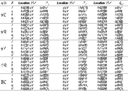
TABLE 1. Maximum values of non-dimensional stresses and their location in curved beamsthe beam. When the value of β is negative, the radial position of the maximum radial and shear stresses occurs near the inner surface of the beam. This is due to the fact that for a negative value of β, the stiffness of the beam decreases from inner surface to the outer one. On the contrary, when the inhomogeneity constant increases to a positive value, the stiffness of the outer surface increases and consequently the radial position of maximum stresses moves to outer surface of the beam. Another interesting point attracting ones attention is that the effect of inhomogeneity constant on the value and location of maximum stresses diminishes when the inner-to-outer radius ratio tends to unity (i.e. thin beam). In this case, the value of maximum non-dimensional shear stress approaches 3/2 and its location is at the middle surface, similar to the Euler-Bernulli beam. It is worth noting that the maximum values of tensile and compressive circumferential stresses always locate on the
surfaces of the beam. Thus, the variation of the inhomogeneity constant may cause the maximum value of tensile circumferential stress to be more than the value of maximum compressive circumferential stress and vice versa (Table 1). In Fig. 2, the nondimensional normal circumferential stress is shown along the radial direction at θ=π/4, for a thick FG curved beam with outer to inner radius ratio b/a=3. It is seen that for a homogeneous curved beam, β=0, there exists a maximum compressive value of circumferential stress at the inner radius of the beam which is more than the amount of the maximum tensile circumferential stress at the outer radius of the beam. By increasing the value of inhomogeneity constant in a FG curved beam, the intensity of compressive circumferential stress at the inner radius of the beam decreases. Regarding the curves of this figure, it can be seen that for a FG curved beam with β=2, the values of the maximum
b
a Location
(
r
,
)
r Location(
r
,
)
Location(
r
,
)
r8 1
2 (0.4857, /2) -1.4313 (1,/2) +6.6837 (0.4857,0) 1.4313
1 (0.2097, /2) -1.5560 (0,/2) -5.1513 (0.2097,0) 1.5560
0 (0.0975, /2) -2.2807 (0,/2) -12.221 (0.0975,0) 2.2807
-1 (0.0646, /2) -3.4095 (0,/2) -24.985 (0.0646,0) 3.4095
-2 (0.0480, /2) -4.8677 (0,/2) -45.742 (0.0480,0) 4.8677
4 1
2 (0.4482, /2) -1.4427 (1,/2) +7.1141 (0.4482,0) 1.4427
1 (0.2886, /2) -1.5345 (0,/2) -6.2529 (0.2886,0) 1.5345
0 (0.1901, /2) -1.7942 (0,/2) -10.506 (0.1901,0) 1.7942
-1 (0.1382, /2) -2.1766 (0,/2) -16.765 (0.1382,0) 2.1766
-2 (0.1069, /2) -2.6657 (0,/2) -25.782 (0.1069,0) 2.6657
2 1
2 (0.4510, /2) -1.4827 (1,/2) +10.403 (0.4510,0) 1.4827
1 (0.3873, /2) -1.5109 (0,/2) -10.159 (0.3873,0) 1.5109
0 (0.3312, /2) -1.5656 (0,/2) -12.882 (0.3312,0) 1.5656
-1 (0.2840, /2) -1.6445 (0,/2) -16.194 (0.2840,0) 1.6445
-2 (0.2451, /2) -1.7459 (0,/2) -20.224 (0.2451,0) 1.7459
4 3
2 (0.4767, /2) -1.4970 (1,/2) +22.112 (0.4767,0) 1.4970
1 (0.4523, /2) -1.5020 (0,/2) -22.073 (0.4523,0) 1.5020
0 (0.4284, /2) -1.5109 (0,/2) -24.295 (0.4284,0) 1.5109
-1 (0.4052, /2) -1.5236 (0,/2) -26.719 (0.4052,0) 1.5236
-2 (0.3829, /2) -1.5403 (0,/2) -29.351 (0.3829,0) 1.5403
8 7
2 (0.4889, /2) -1.4994 (1,/2) +46.042 (0.4889,0) 1.4994
1 (0.4778, /2) -1.5004 (0,/2) -46.035 (0.4778,0) 1.5004
0 (0.4666, /2) -1.5048 (0,/2) -48.235 (0.4666,0) 1.5048
-1 (0.4556, /2) -1.5054 (0,/2) -50.306 (0.4556,0) 1.5054
compressive circumferential stress at the inner edge and maximum tensile circumferential stress at the outer edge of the beam are approximately equal to each other.
The variation of non-dimensional in-plane shear stress across the radial direction is depicted in Fig. 3 for a thick FG curved beam with b/a=3 at θ=π/4. It can be seen that for a homogenous beam, the in-plane shear stress has asymmetric distribution in radial direction with respect to the middle surface
of the beam. This asymmetric distribution of the in-plane shear stress is improved for the FG curved beam by increasing the amount of inhomogeneity constant. It is clear that for β=2 the stress distribution along the radial direction is approximately symmetric. In other word, the peak of the stress occurs at the middle surface of the beam.
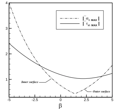
In Fig. 4, the variations of maximum values of the non-dimensional circumferential and shear stresses are depicted versus the inhomogeneity constant for a thick FG curved beam with b/a=3. It is observed that there exists an inhomogeneity constant, β, for which the maximum value of shear stress in the beam becomes minimum. Also, it is seen that by increasing the inhomogeneity constant, the maximum value of compressive circumferential stress in the beam (locates at the inner surface and θ=π/2) decreases, whereas the maximum value of tensile circumferential stress (locates at the outer surface and θ=π/2) increases. Thus, for a specific value of β, the maximum values of tensile and compressive circumferential stresses are equal.
Variations of non-dimensional radial and circumferential deflections of the upper end of the beam versus β are shown respectively in Figs. 5 and 6 for various inner-to-outer radius ratios. It can be seen that by increasing the inhomogeneity constant, both radial and circumferential
-5 -2.5 0 2.5 5
1 2 3 4
|MAX|
|rMAX|
Inner surface
Outer surface
Figure 4. Variation of maximum values of the
non-dimensional circumferential and shear stresses versus the inhomogeneity constant
(r-a) / (b-a)
(b-a)
/P
0 0.25 0.5 0.75 1
-20 -15 -10 -5 0 5 10
=2
=1
=0
=-1
=-2
Figure 2. Variation of the non-dimensional circumferential stress along the radial direction for the FG curved beam
(r-a) / (b-a) r
(b-a)
/P
0 0.25 0.5 0.75 1
0 0.5 1 1.5 2
=2
=1
=0
=-1
=-2
Figure 3. Variation of the non-dimensional shear stress along
deflections of the beam increase. The reason for this is that the stiffness of the inner surface of the beam decreases when β increases. Also, it is concluded that as the inner-to-outer radius ratio increases, the deflection of the curved beam increases.
6. CONCLUSION
In this paper, a closed-form two-dimensional
elasticity solution has been developed for stresses and displacements of a functionally graded curved beam subjected to a shear force at its upper end. The main advantage of designing and analyzing such a beam, composed of functionally graded materials, is the possibility of improving the stress distribution profiles. It has been shown that for a specific value of the inhomogeneity constant, a proper stress distribution along the radial direction is obtained. Moreover, it has been found that all the stress and displacement relations converted to those of a homogenous curved beam, when the inhomogeneity constant approaches zero.
7. REFERENCES
1. Koizumi, M., “The concept of FGM”, Ceramic Trans., Functionally Gradient Materials, Vol. 34, (1993), 3–
10.
2. Dryden, J.: Bending of inhomogeneous curved bars”,
International Journal of Solids and Structures, Vol.
44, (2007), 4158–4166.
3. Yu, A.M. and Nie, G.H., “Explicit solutions for
shearing and radial stresses in curved beams”,
Mechanics Research Communications, Vol. 32,
(2005), 323–331.
4. Shafiee, H., Naei, M.H. and Eslami, M.R., “In-plane and out-of-plane buckling of arches made of FGM”,
International Journal of Mechanical Sciences, Vol.
48, (2006), 907–915.
5. Lim, C.W., Yang, Q. and Lü, C.F., “Two-dimensional
elasticity solutions for temperature-dependent in-plane
vibration of FGM circular arches”, Composite
Structures, Vol. 90, (2009), 323–329.
6. Malekzadeh, P., “Two-dimensional in-plane free
vibrations of functionally graded circular arches with
temperature-dependent properties”, Composite
Structures, Vol. 91, (2009), 38–47.
7. Malekzadeh, P., Atashi, M.M. and Karami, G.,
“In-plane free vibration of functionally graded circular arches with temperature-dependent properties under
thermal environment”, Journal of Sounds and
Vibration, Vol. 326, (2009), 837–851.
8. Saidi, A.R., Jomehzadeh, E. and Atashipour, S.R.,
“Exact analytical solution for bending analysis of functionally graded annular sector plates”,
International Journal of Engineering Transactions A/Basic, Vol. 22, (2009), 307–316.
9. Saidi, A.R., Atashipour, S.R. and Jomehzadeh, E.,
“Exact elasticity solutions for thick-walled fg spherical pressure vessels with linearly and exponentially varying properties”, International Journal of Engineering Transactions A/Basic, Vol. 22, (2009), 405–416. 10. Jomehzadeh, E., Saidi, A.R. and Atashipour, S.R., “An
analytical approach for stress analysis of functionally
E0
u/P
-2 -1 0 1 2
-60 -50 -40 -30 -20 -10
a/b = 0.1 a/b = 0.2 a/b = 0.3 a/b = 0.4
Figure 5. Variation of the radial deflection of the upper end
of the beam versus the inhomogeneity constant
E0
v/P
-2 -1 0 1 2
-30 -20 -10
a/b = 0.1 a/b = 0.2 a/b = 0.3 a/b = 0.4
Figure 6. Variation of the circumferential deflection of the
graded annular sector plates”, Materials and Design,
Vol. 30, (2009), 3679–3685.
11. Hosseini-Hashemi, Sh., Akhavan, H., Rokni, H., Daemi, N. and Alibeigloo, A., “Differential quadrature analysis of functionally graded circular and annular sector plates on elastic foundation”, Materials and Design, Vol. 31,
(2010), 1871–1880.
12. Yu, A.M., Yang, C.J. and Nie. G.H., “Analytical
formulation and evaluation for free vibration of
naturally curved and twisted beams”, Journal of
Sounds and Vibration, Vol. 329, (2010), 1376–1389.
13. Nosier, A. and Fallah, F., “Reformulation of Mindlin– Reissner governing equations of functionally graded circular plates”, Acta Mechanica. 198, 209–233 (2008)
14. Tutuncu, N., “Stresses in thick-walled FGM cylinders with exponentially-varying properties. Engineering Structures, Vol. 29, (2007), 2032–2035.
15. Kashtalyan, M., “Three-dimensional elasticity solution for bending of functionally graded rectangular plates”,
European Journal of Mechanics A/Solid, Vol. 23,
(2004), 853–864.
16. Tutuncu, N. and Ozturk, M., “Exact solutions for
stresses in functionally graded pressure vessels”,
Composites Part B/Engineering, Vol. 32, (2001), 683– 686.
17. Timoshenko, S.P. and Goodier, J.N., “Theory of