Please cite this article as: S. Safarian, M. Tahani, Study of Stone-wales Defect on Elastic Properties of Single-layer Graphene Sheets by an Atomistic based Finite Element Model,International Journal of Engineering (IJE),IJE TRANSACTIONS C: Aspects Vol. 31, No. 3, (March 2018) 456-463
International Journal of Engineering
J o u r n a l H o m e p a g e : w w w . i j e . i rStudy of Stone-wales Defect on Elastic Properties of Single-layer Graphene Sheets
by an Atomistic based Finite Element Model
S. Safarian, M. Tahani*
Department of Mechanical Engineering, Faculty of Engineering, Ferdowsi University of Mashhad, Mashhad, Iran
P A P E R I N F O
Paper history: Received 13August2017
Received in revised form 20September2017 Accepted 12October2017
Keywords:
Graphene Sheet Defects Atomistic Model Finite Element Method Elastic Properties
A B S T R A C T
In this paper, an atomistic based finite element model is developed to investigate the influence of topological defects on mechanical properties of graphene. In general, plane stiffness matrix of the hexagonal network structure of graphene is found. The effective elastic modulus of a carbon ring is determined from the equivalence of molecular potential energy related to stretch and angular deformation. A hexagonal carbon ring as a unit cell of the graphene sheet is modeled by four-node elements. Applying three-node triangular elements, Stone-Wales (SW) defect which is an important topological defect is also modeled. In this method, both pristine structure of graphene and graphene with SW defect are considered and to get more real structure, an atomistic model of a small part of graphite sheet around the defect site, is modeled in Gaussian software and new arrangement around SW defect are obtained by minimizing its energy. Young’s modulus, shear modulus and Poisson’s ratio of the pristine single-layered graphene sheet (SLGS) and the effect of topological defects on the elastic properties of SLGS were examined. The numerical results from this new model showed good agreement with data available in literature.
doi: 10.5829/ije.2018.31.03c.08
NOMENCLATURE
K Stiffness u Potential constant of Lennard–Jones
J Jacobian operator r0 Equilibrium distance
E Elasticity matrix rij Distance between interacting atoms i and j
B Strain-displacement matrix, Ur Potential energy for stretching
d diameter Uθ Potential energy for bending
t Thickness Uτ Potential energy for torsion
E Modulus of elasticity kr Bond stretching constant
A Cross-sectional area kθ Bond bending constant
U Modified Morse potential energy kτ Bond torsional constant
De Morse potential parameter I Moment of inertia
ks Morse potential parameter Greek Symbols
kθ Morse potential parameter ν Poisson's ratio
UvdW Lennard–Jones ‘‘6–12’’ potential Morse potential parameter
1. INTRODUCTION1
The remarkable properties and applications of carbon materials such as nanotubes and graphene explain their exclusive scientific and importance and have motivated great research efforts in recent years [1]. Graphene was under intensive research since it was discovery in 2004.
*Corresponding Author’s Email:[email protected] (M. Tahani)
There has been great research on how to model graphene, using molecular mechanics (MM) or molecular dynamics (MD). Graphene sheets showed several desirable physical properties, such as small size, low density, high hardness, high strength and excellent electrical and thermal properties [2].
physical functionalities such as electrical and thermal conductivities [3]. Using these reinforcing agents to prepare strong nanocomposites with admirable inestimable mechanical properties needs to come to understanding of the mechanical behavior of such nanostructures. However, it is not easy to predict directly the mechanical properties of nanostructures because of their anisotropic properties, morphology and existence of defects. Thus, it is desirable to carry out analytical or numerical analyzes to understand how graphene affect the mechanical behavior of composites and how the morphology and topological defects decrease idealistic physical properties.
Many researchers on SLGS have focused on their material properties [4-9]. Most studies assumed isotropic material properties for SLGS, except in some literature [9]. However, high variability of Young's modulus and Poisson's ratio, as well as the effective thickness have been reported in the literature [10-17]. A wide scattering of mechanical properties of SLGS can be largely associated with the misgiving of its thickness and lack of attention to topological defects. The thickness of one graphene layer is assumed to be 0.34 nm in most published research papers [5, 6, 8, 9]. The 0.34 nm value provides in-plane Young’s modulus of about 1 TPa [10]. During this study, we believed that the mechanical behavior of SLGS was anisotropic and also chirality- and size-dependent. An isotropic mechanical properties for a sheet of graphene along different load directions are attributed to the hexagonal structure of the graphene [11]. Because of the difference of bond’s angle in direction of armchair and zigzag in the hexagonal structure of a graphite sheet, it shows orthotropic mechanical properties. Topological defects like SW defect are created during the synthesis and after purification, so they changed the mechanical behavior of graphene sheets. Therefore, all material properties of a pristine SLGS and SLGS with SW defect need to be properly estimated. It is difficult to measure directly the mechanical properties of SLGS in the experiment, because of problems in the tests at the nanoscale.
Recently, continuum-based models for SLGS have been developed using the harmonic energy potential. Effects of various defects on the mechanical behavior of graphene sheets were studied using molecular methods by Tserpes et al. [18]. Molecular mechanics/dynamics and ab-initio methods are suitable for checking defects but they were limited in scale and computationally expensive. Continuum models reduce computational cost significantly, while continuum mechanics models did not develop well to predict the effects of defects on mechanical properties of CNT and SLGS.
Researches comprising the SW defects
accomplished by Tserpes et al. [19, 20] using the finite element method (FEM) do not contain the deformation of the original nanotube structure around the nucleation
site, which may not be true in generalas atoms rearrange to minimize their energy. They applied finite element method to analyze the nanotube structure and the modified Morse interatomic potential to simulate the non-linear force field of the C–C bonds. Xiao et al. [2, 21] used the modified Morse potential to investigate the mechanical response of defective carbon nanotubes and graphene sheets. An interaction mechanics approach, the SW defect formation was incorporated into their model. Consequently, they studied the effect and interaction of multiple defects on an SWCNT.
We propose a new continuum-atomistic model to study the effect of SW (5-7-7-5) defect on elastic properties of SLGS. The deformations caused by the formation of the SW defect is considered. The hexagons far away from the defect are modeled by an atomistic based FEM established from six four-node elements. The positions of atoms near the defect are determined by atomistic calculations coupled with the atomistic-based continuum model. It was found that SLGS show anisotropic behavior and they were really affected by topological defects.
2. SIMULATION METHOD
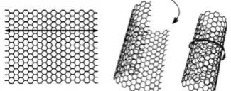
A single layer of the lattice structure, as shown in Figure 1, can be thought of as an unraveled single wall carbon nanotube (CNT).
An SLGS can be considered as a thin homogeneous layer which is made-up of covalently bonded carbon atoms and is organized in identical hexagonal carbon rings which are bonded to each other forming a lattice structure. The discrete elements of the graphene structure provide convenience for analysis by the finite element method (see Figure 2). It is assumed that SLGS is often under in-plane (2D) stress because the in-plane dimensions of the sheet are enough large compared with the graphene sheet’s effective thickness.
2. 1. Stiffness Matrix of SLGS A displacement-based finite element approach for modeling the graphene structure and deriving the stiffness matrix of hexagonal carbon ring is presented. The area covered by carbon ring could be broken down into isosceles trapezoidal elements allowing the structure to be mapped to a square element in r-s coordinate as shown in Figure 3 [22].
Figure 2. An unraveled partial lattice structure of graphene sheet and the equilateral hexagons or carbon rings.
Figure 3. An isosceles trapezoid from the hexagonal carbon ring in x-y space, with its mapped structure in an alternate r-s coordinates.
Using strain-displacement relations from elasticity, the stiffness matrix of six possible trapezoids located in hexagon ABCDEF marked as ABCF, BCDA, CDEB,
DEFC, EFAD and FABE (see Figure 4) is derived. For example, the stiffness of trapezoid KABCFis found through the displacement based finite element analysis by the following equation:
1 1
1 1
det (
T ABCF
K J tdrds
B EB ) (1)where,J is the Jacobian operator, E is the elasticity matrix which is derived directly from the stress-strain relations and Hook’s law, B is the strain-displacement matrix, BT is the transpose of the strain-displacement matrix, r-s are coordinates which are shown in Figure 3 and t is the thickness of the element. The stiffness of other trapezoids is obtained by applying correct rotation matrix. These six distinct trapezoids of the carbon ring cover the hexagon’s area three times. Thus, the (12×12) global stiffness matrix of the hexagon ABCDEF is one-third of the sum of the six (8×8) local stiffness matrix of the trapezoidal components.
Figure 4. The hexagon ABCDEF withthree equally links between CF, BE and AD.
2. 2. Continuum-Atomistic Model for Stone-Wales Defect A graphene sheet is a hexagonal lattice of carbon atoms which hexagonal elements have expanded in a planar shape and if rolled in cylindrical shell carbon nanotube is formed.Thus, a carbon nanotube with a large diameter and high aspect ratio act locally such as graphene. Therefore, if we ignore the effect of curvature for the CNTs, they will be comparable [23].
It is proved that defects can growth at purification or during processing like chemical functionalization [24]. Research has shown that even a few defects in the atomic lattice will result in some degradation of their mechanical properties [24, 25]. Whereas theoretical calculations are typically performed on perfect structures, it is nearly impossible to obtain perfect SLGS samples. Ebbesen et al. [26] classified the defects into three groups: (a) topological defects, (b) rehybridization defects and (c) incomplete bonding.
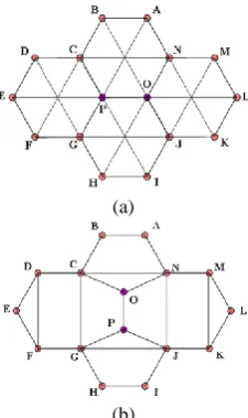
The SW defect is one of the most important topological defects in CNTs and graphene sheets. Such defect is produced by 90° rotation of a C–C bond (Figures 5(a) and (b)) [12, 24, 25]. Four hexagonal cells comprising these atoms transform into one pair of pentagonal cells and another pair of heptagonal cells. Although energy is needed to create the SW defect but the SLGS with SW defect is stable. This means that the transition to the perfect structure does not occur spontaneously by relaxation. An isolated SW defect affects the geometry of the SLGS only locally in its neighborhood. This means that the induced perturbation is not enough strong to cause a global instability.
(a)
(b)
However, the defect does have a significant degrading influence on the mechanicalproperties of the graphene sheets [27].
In this paper, the effect of 5-7-7-5 defects on Young’s modulus, shear modulus, and Poisson’s ratio of graphene sheet of various sizes is considered. The rotated bond before and after the transformation is shown in Figure 5(a) and (b), respectively.
The atoms can be divided into two groups, those atoms around the defect and those atoms away from the defect. Atoms which are away from defect undergo relatively uniform deformation since the effect of bond rotation has no effect on them. Therefore, the positions of these atoms (far away from the defect) can be determined regularly from the hexagonal structure of pristine graphene. The structure of a perfect plate and its SW defect is optimized by Gaussian quantum package version 03 [28] to find the exact position of atoms after producing this defect. The model contains 102 atoms with 502 electrons. The degree of freedom for each atom is three and there is no constraint on the atoms (Figure 5(a) and (b)). Such an approach involves both continuum and atomistic calculations and is therefore called a continuum-atomistic model [29].
Similar to the hexagonal element, the stiffness matrix of heptagonal and pentagonal elements are obtained based on the finite element approach. As mentioned before the area of SW defect covered by four 5-7-7-5 rings that could be broken down into isosceles trapezoidal, rectangular and triangular elements as shown in Figure 6. The trapezoidal, rectangular and triangular elements located in heptagon and pentagon mark as OCGP, OPJN, CDFG, MNJK, DEF, MKL for heptagonal elements, and ABCN, HIJG and NCO, GJP
for pentagonal elements (see Figure 6(b)).
(a)
(b)
Figure 6. (a) The hexagons that are broken down into six trapezoid elements. (b) 5-7-7-5 rings that are broken down into isosceles trapezoidal, rectangular and triangular elements
The stiffness K of triangular elementsis found through the formal approach of the FEM from Equation (1) as follows:
1 2 3
1 2 3
1 2 3 1 2 3
1 2 3 2 1 3 3 1 2
1 2 3 2 1 3 3 1 2
, 4 (1 )
0 0 0 1 0
0 0 0 , 1 0 ,
1 0 0
2
( ), ( ), ( ),
( ), ( ), ( )
T 2
Εt K
Α ν
y y y y y y
x x x x x x
B EB
B E (2)
The pair (xi, yj) is the triangular node’s coordinate. The Latin indices such as i, j and k vary from 1 to 3, E is the modulus of elasticity of the material, t is constant thickness, A is uniform cross-sectional area and ν is Poisson’s ratio. The stiffness of other isosceles trapezoidal and rectangular elements are obtained by applying Equation (1).
3. ANALYTICAL MODEL TO DETERMINE
PROPERTIES
As it is seen from Equations (1) and (2), the stiffness matrix of an element is obtained by integrating certain properties, but in fact, there are two unknowns as elastic and geometric parameters that should be determined; E
and t. Thus, two parameters E and t are still unknown for all three types of elements hexagonal, heptagonal and pentagonal. As mentioned earlier, six atoms are arranged in identical hexagonal carbon rings which are bonded together by six covalent bonds and six possible van der Waals (vdW) non-bonding interactions. For heptagonal and pentagonal elements this occurs for 7 or 5 atoms, respectively (see Figure 6).
In this analytical model, we take into account all bonded and non-bonded interactions for the elements. The two other unknowns are determined by equating energy of the considered carbon ring with those of hexagon ABCDEF in Figure 6 which has three equally weighted links between CF, BE and AD. Similarly equating energy is applied to determine Young’s modulus and thickness for the heptagonal and pentagonal elements. For equating strain energy, carbon ring may be subjected to the predefined deformations along two perpendicular armchair and zigzag directions (see Figure 2), which are standard tests [3]. The tensile tests in directions 1 and 2 and shear test are applied to determine equivalent E and t for hexagonal, heptagonal and pentagonal elements (see Figure 7).
(Δ )
2 1 2 41 1 (Δ ) [1 (Δ ) ]
2
r
e s
UD e k k
(3)
where
4 10 1
18 2
10
Δ , Δ ,
0.754rad , 2.625 10 m , 2.094rad, 0.9 10 Nm rad ,
6.03105 10 Nnm, 0.139nm
s
e
r r r
k
k
D r
(4)
and the general Lennard–Jones ‘‘6–12’’ potential is commonly expressed as:
12 6
0 0
4 ,
vdW
ij ij
r r
U u
r r
12 6
2
0 0
2 2
d
4 156 42
vdW vdW
ij ij
ij ij
U u r r
k
r r
dr r
(5)
where u is the depth, r0 indicates the equilibrium distance of two atoms that make the potential equal to zero, rijis the distance between interacting atoms i and j. In this study, we use the potential constants
4 3.825 10 nNnm
u and r 0.14nm.
Some potential functions have been suggested to describe the interatomic covalent bond of carbon atoms as follows [30, 31]:
2 2
2
1 1
(Δ ) , (Δ ) ,
2 2
1 (Δ ) 2
r r
U k r U k
U U U k
(6)
where, Ur, U, U and Uare energies that are related to the bond stretching, angle variation, dihedral and out-of-plane torsion, respectively. Also, kr, kθ and kτ are the bond stretching, bond angle bending and torsional resistance force constants, respectively; while ∆r, ∆𝜃 and represent bond stretching increment and bond angle and twisting bond angle variation, respectively. Therefore, in small strains and for in-plane tension and shear loading here, we can simplify the potential energies and just the bond stretching and angle variation are applied.These constants were obtained from modified Morse potential for C–C bonds [32].
We assume a circular section for each bond with diameter d and set Ad2/ 4, Id4/ 64. By equating atomistic potential energy from Equations (3) and (5) with strain energy of interactions in a continuum from Equation (6), based on the standard test we obtain d and
E, where d is the diameter of each bond or thickness t of hexagonal, heptagonal or pentagonal elements (see Figure 7).
4. RESULTS AND DISCUSSIONS
The elastic properties of pristine and defective SLGS are obtained using the new continuum-atomistic model.
(a)
(b)
Figure 7.Illustration of the hexagonal carbon ring under (a) in-plane tension and (b) shear loading
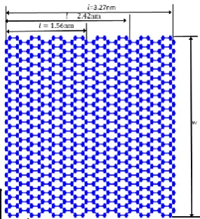
Figure 8 shows graphene sheet with a constant width (w) and different lengths (Ɩ). The finite hexagonal element has 12 degrees of freedom which is used to simulate the SLGS and a total number of elements that we use is about 140-300 hexagons (see Figure 8).
Compared to other finite element approaches the computational cost of the present method is reduced and this is done by a written finite element code. Tserpes and Papanikos [20] used the 3D elastic beam elements for modeling the C–C bonds and at least the number of elements that they were used was six times higher. Figures 9-11 display variations of the elastic properties of defect-free and defective SLGS that are obtained by this new continuum-atomistic model against their length. These results confirm that topological defects affect the elastic properties of SLGS and decrease their properties. Young’s modulus of defect-free SLGS is obtained about 1 TPa. However, Young’s modulus of the SLGS with just one SW defect is found about 0.95 to 0.97 TPa. This confirms the accuracy of the method and shows that SW defect decreases the tensile modulus and play an important role in tension.
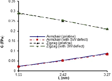
The shear modulus of zigzag and armchair SLGS are also estimated. It is observed that the SLGS shear modulus, based on the arrangement, is about 0.08-0.21 TPa.
Also, it is mentioned that the shear modulus of the SLGS with just one SW defect is of the same order of defect-free one that was reported to be 0.08-0.20 TPa.
Figure 9. Variation of the elastic modulus of pristine and defective armchair graphene sheet for various values of their length (w 4.92nm)
Figure 10. Variation of shear modulus of pristine and defective armchair graphene sheet for various values of their length (w 4.92nm)
Figure 11. Variation of Poisson’s ratio of pristine and defective armchair graphene sheet for various values of their length (w 4.92nm)
The Poisson’s ratio of the SLGS with different chirality is also found. It is observed that when the SLGS get the larger size the results tend to graphene’s properties. It can be seen that our results from both defect-free SLGS and defective SLGS are fairly close to the commonly accepted values.
The elastic properties of pristine and defective zigzag and armchair SLGS are shown in Tables 1 and 2, respectively. The results available in the literature related to the graphene without defects and defective are also compared to evaluate the accuracy of the new continuum-atomistic model.
Talukdar et al. [12] showed that the inclusion of SW defects in SWCNT, generally degrade their mechanical properties. Due to the cut-off function in the Brenner’s bond order potential, it may fail to reveal the exact failure mechanism of the CNTs. Tserpes and Papanikos [19, 20] applied the FEM to defected single walled zigzag, armchair and chiral nanotubes subjected to axial tension.
TABLE 1. Comparison of average values of elastic properties of defect-free SLGS with those available in literature
Sources E (TPa) G
(TPa) ν
Present (Armchair) 1.0225 0.088 0.235
Present (Zigzag) 0.992 0.210 0.176
Lee et al. [10] (Experiment) 1.000 - -
Shokrieh et al. [13] (MM) 1.040 - -
Bu et al. [14](Atomistic) 1.240 - -
Tsai et al. [15] (MD) 0.912 0.358 0.261
Ni et al. [11] (MD) 1.091 - -
Sakhaee Pour. [8](Armchair) 1.042 0.228 1.285
Sakhaee Pour. [8] (Zigzag) 1.040 0.213 1.441
Scarpa et al. [9] (Amber
model) 1.305 0.208 0.568
Scarpa et al. [9] (Morse
model) 1.668 0.213 0.574
Georgantzinos et al. [16]
(FEM) 1.367 0.280 0.603
Kudin et al. [4](ab initio) 1.029 - 0.149
Reddy et al. [7] (Armchair) 1.095-1.125 - 0.445-0.498
Reddy et al. [7] (Zigzag) 1.106-1.201 - 0.442-0.465
Talukdar [12] (Bond
potential) 1.44 - -
Talukdar [12]
(Tight-binding) 1.131 - -
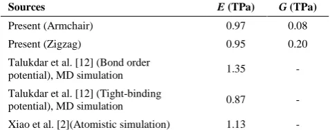
TABLE 2. Comparison of average values of elastic properties of defective SLGS with those available in literature
They concluded that the differences between the theoretical predictions and experimental measurements of Young’s modulus may depend on number of defects. Xiao et al. [2, 21] studied the influence of single and multiple defects on mechanical properties of carbon nanotubes and graphene sheets. Their results showed that increasing the number of defects along the hoop direction can change Young’s modulus of SWCNT dramatically, particularly when the defect distance is smaller than 2 nm.
The assessment of the accuracy of the present results are obtained by comparing them with those obtained by published experimental works and numerical models. The comparisons confirm that Young’s modulus and shear modulus in both directions change with the influence of SW defect. This model predicts that Young’s modulus decreases approximately 4 to 5% for defective SLGS relative to defect-free SLGS in zigzag and armchair directions, respectively. Also, shear modulus decreases 4 to 9% for defective SLGS relative to defect-free SLGS in zigzag and armchair directions, respectively. It is also found that defective and defect-free SLGS show anisotropic behavior and they are really affected by topological defects. In our view, use of this method has two basic advantages which make this method very efficient and reliable. First, the present atomistic based finite element model has simplified formulas while considering four-node elements and three-node triangular elements to model SW defect. Second, in atomistic view, anew arrangement of atoms around SW defect are obtained by minimizing its energy which was ignored in previous studies and these bring the results of our model closer to reality.
5. CONCLUSIONS
By incorporating the atomistic simulation into a finite element model, the mechanical responses of defected graphene sheet under tension and shear loading are investigated in this paper. The present approach predicts Young’s modulus, shear modulus and Poisson’s ratios of graphene sheets with or without SW defect. SLGS subjected to uniaxial tension and shear load are simulated. The results reported that Young’s modulus
and shear modulus in both directions change with the influence of defects. It is found that defective and defect-free SLGS show anisotropic behavior and they are really affected by topological defects.
The most important innovation in this finite element method is that the area of carbon ring is covered by six isosceles trapezoidal elements and total number of elements is drastically reduced compared with other finite element approaches. Another novelty in this model is that the new arrangement of the atoms after the rotation of the carbon bond is considered by Gaussian software and these new coordinates are used in the finite element model. An atomistic approach is used to model the formation of a 5-7-7-5 SW defect in SLGS which could give the local deformation and reconfiguration. The proposed method is possible for different forms and density of SW defects and other topological defects like a vacancy.Using this new method, modeling SLGS and CNT is much simpler and computationally more efficient than molecular dynamics model. Even other nanostructures like Boron-Nitride nanotube could also be simulated by this model.
6. REFERENCES
1. Cranford, S.W. and Buehler, M.J., "Mechanical properties of graphyne", Carbon, Vol. 49, No. 13, (2011), 4111-4121. 2. Xiao, J.R., Staniszewski, J. and Gillespie, J.W., "Tensile
behaviors of graphene sheets and carbon nanotubes with multiple stone–wales defects", Materials Science and
Engineering: A, Vol. 527, No. 3, (2010), 715-723 0921-5093.
3. Cho, J., Luo, J.J. and Daniel, I.M., "Mechanical characterization of graphite/epoxy nanocomposites by multi-scale analysis",
Composites Science and Technology, Vol. 67, No. 11, (2007),
2399-2407.
4. Kudin, K.N., Scuseria, G.E. and Yakobson, B.I., "C 2 f, bn, and c nanoshell elasticity from ab initio computations", Physical
Review B, Vol. 64, No. 23, (2001), 235406.
5. Huang, Y., Wu, J. and Hwang, K.C., "Thickness of graphene and single-wall carbon nanotubes", Physical Review B, Vol. 74, No. 24, (2006), 245413.
6. Hemmasizadeh, A., Mahzoon, M., Hadi, E. and Khandan, R., "A method for developing the equivalent continuum model of a single layer graphene sheet", Thin Solid Films, Vol. 516, No. 21, (2008), 7636-7640.
7. Reddy, C.D., Rajendran, S. and Liew, K.M., "Equivalent continuum modeling of graphene sheets", International Journal
of Nanoscience, Vol. 4, No. 04, (2005), 631-636.
8. Sakhaee-Pour, A., "Elastic properties of single-layered graphene sheet", Solid State Communications, Vol. 149, No. 1, (2009), 91-95.
9. Scarpa, F., Adhikari, S. and Phani, A.S., "Effective elastic mechanical properties of single layer graphene sheets",
Nanotechnology, Vol. 20, No. 6, (2009), 065709.
10. Lee, C., Wei, X., Kysar, J.W. and Hone, J., "Measurement of the elastic properties and intrinsic strength of monolayer graphene",
Science, Vol. 321, No. 5887, (2008), 385-388.
11. Ni, Z., Bu, H., Zou, M., Yi, H., Bi, K. and Chen, Y., "Anisotropic mechanical properties of graphene sheets from molecular dynamics", Physica B: Condensed Matter, Vol. 405, No. 5, (2010), 1301-1306.
12. Talukdar, K. and Mitra, A.K., "Comparative md simulation study on the mechanical properties of a zigzag single-walled
Sources E (TPa) G (TPa)
Present (Armchair) 0.97 0.08
Present (Zigzag) 0.95 0.20
Talukdar et al. [12] (Bond order
potential), MD simulation 1.35 -
Talukdar et al. [12] (Tight-binding
potential), MD simulation 0.87 -
carbon nanotube in the presence of stone-thrower-wales defects", Composite Structures, Vol. 92, No. 7, (2010), 1701-1705.
13. Shokrieh, M.M. and Rafiee, R., "Prediction of young’s modulus of graphene sheets and carbon nanotubes using nanoscale continuum mechanics approach", Materials & Design, Vol. 31, No. 2, (2010), 790-795.
14. Bu, H., Chen, Y., Zou, M., Yi, H., Bi, K. and Ni, Z., "Atomistic simulations of mechanical properties of graphene nanoribbons",
Physics Letters A, Vol. 373, No. 37, (2009), 3359-3362.
15. Tsai, J.-L. and Tu, J.-F., "Characterizing mechanical properties of graphite using molecular dynamics simulation", Materials &
Design, Vol. 31, No. 1, (2010), 194-199.
16. Georgantzinos, S.K., Giannopoulos, G.I. and Anifantis, N.K., "Numerical investigation of elastic mechanical properties of graphene structures", Materials & Design, Vol. 31, No. 10, (2010), 4646-4654.
17. Van Lier, G., Van Alsenoy, C., Van Doren, V. and Geerlings, P., "Ab initio study of the elastic properties of single-walled carbon nanotubes and graphene", Chemical Physics Letters, Vol. 326, No. 1–2, (2000), 181-185.
18. Khare, R., Mielke, S.L., Paci, J.T., Zhang, S., Ballarini, R., Schatz, G.C. and Belytschko, T., "Coupled quantum mechanical/molecular mechanical modeling of the fracture of defective carbon nanotubes and graphene sheets", Physical
Review B, Vol. 75, No. 7, (2007), 075412.
19. Tserpes, K.I., Papanikos, P. and Tsirkas, S.A., "A progressive fracture model for carbon nanotubes", Composites Part B:
Engineering, Vol. 37, No. 7, (2006), 662-669.
20. Tserpes, K.I. and Papanikos, P., "The effect of stone–wales defect on the tensile behavior and fracture of single-walled carbon nanotubes", Composite Structures, Vol. 79, No. 4, (2007), 581-589.
21. Xiao, J.R., Staniszewski, J. and Gillespie Jr, J.W., "Fracture and progressive failure of defective graphene sheets and carbon nanotubes", Composite Structures, Vol. 88, No. 4, (2009), 602-609.
22. Samaroo, K.J., "Stiffness matrices of carbon nanotube structures", (2005),MIT ThesesPublisher: Massachusetts Institute of Technology.
23. Mohammadiana, M. and Fereidoonb, A., "Young's modulus of single and double walled carbon nanocones using finite element method", International Journal of Engineering-Transactions
C: Aspects, Vol. 27, No. 9, (2014), 1467-1474.
24. Moshrefzadeh-Sani, H., Saboori, B. and Alizadeh, M., "A continuum model for stone-wales defected carbon nanotubes",
International Journal of Engineering-Transactions C:
Aspects, Vol. 28, No. 3, (2015), 433-439.
25. Sadrnejad, S.A., Chaboki, A. and Yahyaei, M., "Inelastic continuum modeling of carbon nanotube's behavior using finite element method", International Journal of
Engineering-Transactions A: Basics, Vol. 20, No. 2, (2007), 129-135.
26. Ebbesen, T.W. and Takada, T., "Topological and sp 3 defect structures in nanotubes", Carbon, Vol. 33, No. 7, (1995), 973-978.
27. Pozrikidis, C., "Effect of the stone–wales defect on the structure and mechanical properties of single-wall carbon nanotubes in axial stretch and twist", Archive of Applied Mechanics, Vol. 79, No. 2, (2009), 113-123.
28. Gaussian, R.A., "1, mj frisch, gw trucks, hb schlegel, ge scuseria, ma robb, jr cheeseman, g. Scalmani, v. Barone, b. Mennucci, ga petersson et al., gaussian", Inc., Wallingford CT, (2009).
29. Jiang, H., Feng, X.Q., Huang, Y., Hwang, K.C. and Wu, P.D., "Defect nucleation in carbon nanotubes under tension and torsion: Stone–wales transformation", Computer Methods in
Applied Mechanics and Engineering, Vol. 193, No. 30, (2004),
3419-3429.
30. Tersoff, J., "Empirical interatomic potential for carbon, with applications to amorphous carbon", Physical Review Letters, Vol. 61, No. 25, (1988), 2879-2886.
31. Brenner, D.W., "Empirical potential for hydrocarbons for use in simulating the chemical vapor deposition of diamond films",
Physical Review B, Vol. 42, No. 15, (1990), 9458-9467.
32. Cornell, W.D., Cieplak, P., Bayly, C.I., Gould, I.R., Merz, K.M., Ferguson, D.M., Spellmeyer, D.C., Fox, T., Caldwell, J.W. and Kollman, P.A., "A second generation force field for the simulation of proteins, nucleic acids, and organic molecules",
Journal of the American Chemical Society, Vol. 117, No. 19,
(1995), 5179-5197.
Study of Stone-wales Defect on Elastic Properties of Single-layer Graphene Sheets
by an Atomistic based Finite Element Model
S. Safarian, M. Tahani
Department of Mechanical Engineering, Faculty of Engineering, Ferdowsi University of Mashhad, Mashhad, Iran
P A P E R I N F O
Paper history: Received 13August 2017
Received in revised form 20September 2017 Accepted 12October 2017
Keywords: