Please cite this article as:M. Bidabadi, M. J. Noroozi, Effect of Heat Recirculation in Biomass Flame Stability within a Cylindrical Micro-Combustor, International Journal of Engineering (IJE), TRANSACTIONS C: Aspects Vol. 28, No. 3, (March 2015) 454-459
International Journal of Engineering
J o u r n a l H o m e p a g e : w w w . i j e . i rEffect of Heat Recirculation in Biomass Flame Stability within a Cylindrical
Micro-Combustor
M. Bidabadi a, M. J. Noroozi * b
a Combustion Research Laboratory, School of Mechanical Engineering, Iran University of Science and Technology, Tehran, Iran
b Departmnet of Mechanical Engineering, University of Ayatollah ozma Boroujerdi, Boroujerd, Iran
P A P E R I N F O
Paper history: Received 16 October 2014
Received in revised form 15 November 2014 Accepted 18 December 2014
Keywords:
Analytical Model Heat Recirculation Wood Particles Burning Velocity Blow-Off Limits
A B S T R A C T
Flame stability inside a cylindrical micro-combustor was studied. Considering the occurrence of heat recirculation, the respective relations were written; with parameters such as motion speed of reactants, flame propagation speed and thermal conductivity of the combustor wall. The flame stability as well as its location inside the micro-combustor were also studied. It was found that for each thermal conductivity of the combustor wall, there was only one point inside the micro-combustor. If the flame was formed in that point, it would remain stable inside the micro-combustor. It was also found that for each thermal conductivity of the combustor wall, the flame inside the combustor remained stable, only in one specified range of motion speed of the reactants. In addition, blow-off limits were obtained for high and low speeds of reactants inside the combustor for different values of thermal conductivity of the combustor wall.
doi: 10.5829/idosi.ije.2015.28.03c.16
1. INTRODUCTION1
The unique role of heat recirculation in new thermal systems has led to studying this phenomenon extensively in the world. In study of many combustion and heat transfer systems, we face the heat recirculation phenomenon. Heat recirculation means that when combustion occurs, some of its thermal energy transfers into the material which should be combusted. In this regard, the total enthalpy of reactants (sum of thermal and chemical enthalpies) is higher than the cold reactants (without heat recirculation). Therefore, combustion will be preserved with heat recirculation under conditions such as diluted mixtures, fuels with low thermal value, high heat losses, etc., which leads to extinction of the flame [1].
Today, the application of combustion devices has been increased, facing the heat recirculation issue. Therefore, the study of this subject is of special importance for modeling such devices. The increasing
1*Corresponding Author’s Email: [email protected] (M. J.
Noroozi)
use of Micro Electro-Mechanical Systems (MEMS) developed a new generation of power generating sources with smaller sizes and higher energy densities. Their important applications include gas micro - turbine
[2], micro - thermoelectric equipment [3],
thermophotovoltaic systems [4], and production of propulsion force in pico - and nano-satellites.
The intention of scientists to replace these systems with conventional electrochemical batteries has attracted the attention of many researchers [5]. In MEMS, electric power is generated from combustion, in such way that heat or radiation resulting from combustion is converted into electrical energy with thermoelectric or thermophotovoltaic elements [6]. Heat losses and friction in small sizes have become important and effective phenomena. Therefore, it is not possible to design equipment with very small sizes based on equipment with conventional sizes such as internal combustion engines. For this reason, heat recirculation should be used in these systems.
Hydrocarbon fuels contain about 100 times more energy in one equal mass unit compared with lithium ion batteries (as one of the generating sources of
power). Therefore, the equipment that converts fuel into electrical energy with an efficiency of more than 1% of chemical to electrical energy conversion is better than today’s conventional electrical batteries [1].
Limited and decreasing fossil fuel sources in addition to pollutions resulting from burning of these valuable sources have motivated authorities of energy section in developed countries to replace these resources with renewable and sustainable ones. One of the largest non-fossil resources is biomass, which has played an effective role in human life since its emergence until now. Since biomass is in solid phase, it is produced by nature and is found in different forms and sizes. The replacement of these resources with fossil resources has been challenging. A solution for this problem is biomass crushing with very small sizes and its suspension in air, so that it forms a solid particle cloud. In this manner, it gets close to an oxidizer and the fuel gaseous mixture. Consequently, flame propagation in this particle cloud is comparable to flame propagation in a premixed reactant gas [7].
Wood dust consists of tiny particles of wood produced during the processing and handling of wood, chipboard, and/or hardboard. Worker exposure is high in many industries, including logging and sawmill operations, furniture and paper manufacturing, and construction of residential and commercial buildings. Operations within these industries, such as sawing, routing and turning; sanding, by machine and by hand; and using compressed air lines to blow dust off furniture and other particles before spraying are the most likely to produce high dust levels.
Recently, some studies has been carried about combustion of bio-fuels. Hassani et al. [8] studied about two-step catalytic production of biodiesel from waste cooking oil. A model for heat-recirculating micro combustor using wood dust is developed by Bidabadi et al. [9]. Jafarmadar and Pashae [10] investigated the effect of castor oil biodiesel fuel on performance and emissions of a diesel engine experimentally.
Flame stability in micro-channels has a different behavior from other conventional sizes. The reactive areas are wider and the burning velocity is higher than the values we expect from free flame propagation. These behaviors are results of heat recirculation from the post-flame zone to the pre-flame zone through the structure of micro-combustor. This heat coupling increases the flame stability limits [11]. This finding is in line with previous analytical works in this field, which announced that the interaction between flame and its surrounding increases its stability [12]. The next experimental works confirmed these results and this process was called thermally stabilized combustion [13].
In this paper, we tried to improve our understanding of the main physical mechanisms for increasing flame stability in micro-combustors. This was performed
through developing a simple analytical model for flame propagation in a narrow channel.
2. MATHEMATICAL MODEL
The analytical model applied here is based on the model of Ref. [8]. Figure 1 shows the schematics of a stabe flame in a cylindrical micro-combustor.
Diameter of the combustor is H and thickness of its wall is t. Length of the channel is L and position of the flame based on the flow inlet is xflame. Wood and air
particle cloud premix enters with equivalence ratio of φ=1, pressure of 1 atm and velocity of U from the left side. A one-dimensional model is used for elaboration of heat exchange in direction of flow. The channel is divided into three parts: the preheat zone in which temperature of gas increases from the inlet temperature, T0 to the preheat temperature, Tph, the reactive zone in
which gas temperature rapidly increases from the preheat temperature to the adiabatic temperature of flame, Tad and the post flame zone in which gas
temperature is reduced to temperature Tf due to the heat
loss to wall of the channel. This temperature is obtained by writing a conservation of energy equation:
loss loss
f ad ad
r p
Q Q
T T T
A UC M
r
-
-= = (1)
where, Qloss is the heat loss to the wall and Ar is gas
flow cross section. To mention heat exchange process between gas and wall of structure, thermal resistance networks can be used [14]. Figure 2 shows the applied network for showing exchange of heat between gas, structure and environment.
It is necessary to note that we analyze only the upper half of the shape due to symmetry. In this network, RS is
resistance to the conductive heat transfer in the structure of combustor, Rb1 and Rb2 are resistances to the
convection heat transfer between gas and internal wall of combustor in the preheat zone and the post flame zone, Re1 and Re2 are resistances to convection heat
transfer between environment and external wall of combustor in preheat and post-flame regions.
These resistances are calculated as follows:
1
. ,
2 ,
1
,
2
,
1 , ,
. .
1 1
,
. . . .
1 1
,
. . .( ) .
1 1
,
2 . . . .
1
. 2 . . .( )
r
S r b
S S r r in in pre
b
r flame in in post
e
r flame out out pre
e
out flame out out post
out flame L
R R R
k A k A h A
R
k Nu x h A
R
k Nu L x h A
R
h R x h A
h R L x
d
p
p
p
p
= = = =
= =
= =
-= =
Figure 1. Schematics of stabe flame in a cylindrical micro-combustor. [8]
Figure 2. Thermal Resistances Network. [8]
In these equations, KS and Kr are thermal
conductivity of the structure and gas. hin and hout are the
convection heat transfer coefficients in internal and external wall of combustor. AS is the cross section
through which conductive heat transfer is transferred from the post flame zone to the preheat zone in the wall of combustor. Ain,pre, Ain,post, Aout,pre and Aout,post are the
cross sections through which heat transfer is transferred inside and outside combustor and in the preheat and the post flame zones. Nu is Nusselt number relating to the heat transfer between gas and structure and δr is
thickness of flame. Temperature of the wall is calculated in the preheat and post flame zones with heat flux balance in thermal resistance network nodes:
0
1 1 2
1
2
2 0 1 1
2 1 1 1 1 R L
e b S e
s
R L S
R L f
b S f
R L S
R
T R R R R R
T
R R R R R
T R R T A T B
R R C
R
æ + + ö
ç ÷ è ø = -+ + = -(3) 0
2 1 1
2
2
2 0 2 2
2 1 1 1 L L R
e e S b S
s R L S R f b f R L S R R
T R R R R R R
T
R R R R
T R T A T B
R R C
R
æ + + ö
ç ÷ è ø = -+ + = -(4) In which: 2 2 1
1 1 1
R
e b S
R
R R R
=
+ + (5)
1 1
1
1 1 1
L
e b S
R
R R R
=
+ + (6)
Heat loss to environment is calculated as follows:
(
)
(
)(
)
1 0 2 0 2 ] [loss out s flame
s flame
Q h T T x
T T L x
=
-+ - - (7)
Now, we have 4 Equations (1), (3), (4), (7) and 4 unknowns (Tf, Ts1, Ts2, Qloss). A solution for Tf is:
0 1 ad f
A
T T M
T B M -= + (8) In which: 1 2
1 2 1 2
1 1
e e e e
A A
A
CR CR R R
= + - - (9)
1 2 1 2 e e B B B CR CR
= + (10)
Note that Tf depends on xflamethrough different
resistances (Re1, Re2, Rb1, Rb2).
Now, with given Tf, values of Ts1, Ts2 and Qloss are
calculated with above equations. Considering that the heat produced with combustion should be more than the heat loss to the environment, an additional constraint should be applied as follows:
(
0)
L p r f loss
S C A T T Q
r - > (11)
The net heat flux which is transferred from the post flame zone to the preheat zone is determined with the following relation:
1 0 0
1
s f
s
b r
T T T T
Q
R R
-
-= + (12)
Assuming that the heat transfer from the structure to the preheat zone is carried out uniformly, heat flux per surface area is calculated as follows:
For uniform heat flux, increasing of temperature in preheat zone is linear [14]:
0
ph flame
dT
T T x
dx
= + (14)
In which:
s p r
q dT
dx =rUC A (15)
Heat recirculation increases preheat mix temperature by transferring special value of enthalpy from the post flame zone to the preheat zone. This increases burning velocity of the mixture. At the same time, the heat loss on the environment reduces temperature of flame and burning rate. To consider these dependencies, we use the following simplified term for calculation of flame speed which considers preheating effects [15]:
0.375 2exp
2
r
n
A
L ph f
f E
S µT T T- æçè- RT ö÷ø (16)
In which:
2 ph f
T T
T = + (17)
nr is the order of total reaction that its value is 1.33 for
Wood and air particle cloud premix. EA is energy
activation of reaction.
3.
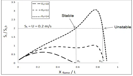
RESULTS AND DISCUSSIONTo investigate the stability limits of combustor, we studied the flame position in the points in which the burning velocity is equal to the inlet speed. Figure 3 shows the diagram of the dimensionless burning velocity in terms of the dimensionless position of flame. This diagram has been drawn for three different values of thermal conductivity in W/mK.
In the Figure, the flame position has become dimensionless with the length of combustor and the flame velocity has become dimensionless with the free flame propagation velocity. This Figure shows that if thermal conductivity of combustor is high enough, the horizontal line corresponding to inlet speed of 0.2 m/s will cut the diagram in two points, indicating the presence of two possible solutions for the position of flame. Only the upstream position (X1) is a stable
solution from amongst these points. If the flame in this point tends forward a little, the burning velocity becomes higher than the motion speed of reactants. Therefore, the flame will tend to move upward, causing it to return to its main position. If the flame position tends backward a little in the same main position, the burning velocity will become lower than the motion speed of reactants.
Figure 3. Dimensionless burning velocity in terms of dimensionless position of flame for 3 different values of thermal conductivity in W/mK. (H=2mm, L=1cm, U=0.2m/s, hout=50W/m2K, SL,fr=0.1 m/s)
Therefore, the flame will tend to move downward, and as a result, it will return to its main position.
Now, we consider the position of downstream flame (X2). If the flame in this point tends forward a little, the
burning velocity becomes lower than the motion speed of reactants. Therefore, the flame will tend to move downward, causing it to exit from the combustor. If the flame position tends backward a little in the same main position, the burning velocity will become higher than motion speed of reactants. Therefore, the flame will tend to move upward, and as a result, it will move toward the entrance of the combustor and exits from it.
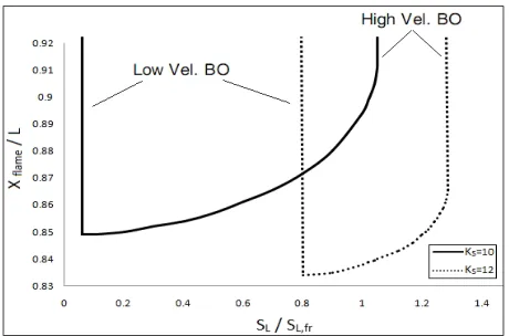
Figure 4. Dimensionless position of flame in terms of dimensionless inlet speed for two different values of thermal conductivity in W/mK. (H=2mm, L=1cm, hout=50W/m2K, SL,fr=0.1 m/s)
Therefore, decrease of the inlet speed reduces the heat for preheating, which leads to reduction of the burning velocity. This reduction process continues with decreasing the inlet speed of reactants, but the difference is that the reduction of the burning velocity has a steeper slope. As a result, the burning velocity becomes lower than the motion speed of reactants in one point and the flame exits from the end of the combustor.
Figure 4 also shows the effect of changes in thermal conductivity of the combustor wall. Increase of kS
directs the stability limits to the right side or higher velocities. The reason is that higher thermal conductivity of the wall causes a more frequent heat recirculation process from the post-flame zone to the preheat zone and facilitates preheating of the inlet reactants. Of course, increase of kS enhances the heat
loss to the environment and finally transfers the low velocity blow-off limit of the flame to higher velocities, which is not desirable.
Figure 5 shows the effect of thermal conductivity of combustor wall on stability limits of flame. The Figure demonstrates that increase in thermal conductivity of combustor wall transfers both low velocity and high velocity blow-off limits to higher velocities. No changes are made in burning velocity in very high or very low values of thermal conductivity of wall. Heat transfer from the post-flame zone to the preheat zone is limited by the convection heat transfer between gas and wall (resistances Rb1 and Rb2). In low values of thermal
conductivity of wall, heat transfer from the post-flame zone to the preheat zone is limited by the conduction of heat transfer through the wall. Therefore, changes of thermal conductivity of wall have no effect on changes of the preheating rate of reactants in very high or very low values of thermal conductivity. This causes the burning velocity to remain constant.
Figure 5. Effect of thermal conductivity of combustor wall on stability limits of flame. (H=2mm, L=1cm, hout=50W/m2K)
4. CONCLUSION
In this paper, we studied the stability of a one-dimensional flame inside a cylindrical micro-combustor. We assumed that some of the heat produced by combustion transferrs to the wall and this heat gets divided into two parts. A part gets lost in the surrounding environment of combustor. Another part gets transferred to the preheat zone through the wall of the micro-combustor and along it. Afterwards, it gets transferred to the reactants and preheats them. Then, we wrote the relations of the problem and extracted the related results. It was found that the thermal conductivity of combustor wall has considerable effect on flame stability and flame is able to be stabilized inside a combustor only in special values of this coefficient. The effect of movement speed of reactants and its interaction with the flame position were studied and the blow-off limits of flame were obtained.
5. REFERENCES
1. Ronney, P.D., "Analysis of non-adiabatic heat-recirculating combustors", Combustion and Flame, Vol. 135, No. 4, (2003), 421-439.
2. Waitz, I.A., Gauba, G. and Tzeng, Y.-S., "Combustors for micro-gas turbine engines", Journal of Fluids Engineering, Vol. 120, No. 1, (1998), 109-117.
3. Sitzki, L., Borer, K., Schuster, E., Ronney, P.D. and Wussow, S., "Combustion in microscale heat-recirculating burners", in The Third Asia-Pacific Conference on Combustion, Seoul, Korea. Vol. 6, (2001), 11-14.
4. Yang, W., Chou, S., Shu, C., Li, Z. and Xue, H., "Development of microthermophotovoltaic system", Applied physics letters, Vol. 81, No. 27, (2002), 5255-5257.
5. Li, J., Chou, S.K., Li, Z. and Yang, W., "Development of 1d model for the analysis of heat transport in cylindrical micro combustors", Applied Thermal Engineering, Vol. 29, No. 8, (2009), 1854-1863.
7. Seshadri, K., Berlad, A. and Tangirala, V., "The structure of premixed particle-cloud flames", Combustion and Flame, Vol. 89, No. 3, (1992), 333-342.
8. Hassani, M., Amini, G., Najafpour, G. and Rabiee, M., "A two-step catalytic production of biodiesel from waste cooking oil",
International Journal of Engineering-Transactions C: Aspects, Vol. 26, No. 6, (2012), 563.
9. Bidabadi, M., Noroozi, M. and Fereidooni, J., "Heat recirculation effect on the structure of wood dust flame propagation", International Journal of Engineering-Transactions B: Applications, Vol. 25, No. 2, (2012), 143. 10. Jafarmadar, S. and Pashae, J., "Experimental study of the effect
of castor oil biodiesel fuel on performance and emissions of
turbocharged di diesel", International Journal of Engineering-Transactions B: Applications, Vol. 26, No. 8, (2013), 905. 11. Leach, T., "Effect of structural heat conduction on the
performance of micro-combustors and micro-thrusters", (2005). 12. Buckmaster, J. and Takeno, T., "Blow-off and flashback of an
excess enthalpy flame", (1981).
13. Churchill, S.W., "Thermally stabilized combustion", Chemical engineering & technology, Vol. 12, No. 1, (1989), 249-254. 14. Mills, A.F., "Basic heat and mass transfer, Pearson College Div,
(1999).
15. Turn s, S.R., "An introduction to combustion, McGraw-hill New York, Vol. 287, (1996).
Effect of Heat Recirculation in Biomass Flame Stability within a Cylindrical
Micro-Combustor
M. Bidabadia, M. J. Noroozib
a Combustion Research Laboratory, School of Mechanical Engineering, Iran University of Science and Technology, Tehran, Iran
b Departmnet of Mechanical Engineering, University of Ayatollah ozma Boroujerdi, Boroujerd, Iran
P A P E R I N F O
Paper history: Received 16 October 2014
Received in revised form 15 November 2014 Accepted 18 December 2014
Keywords:
Analytical Model Heat Recirculation Wood Particles Burning Velocity Blow-Off Limits
ﺪﯿﮑﭼ
ﺖﻓﺮﮔراﺮﻗﯽﺳرﺮﺑدرﻮﻣياﻪﻧاﻮﺘﺳارﻮﺘﺳﺎﺒﻣﺎﮐوﺮﮑﯿﻣﮏﯾنورد،ﻪﻠﻌﺷيراﺪﯾﺎﭘ
.
شدﺮﮔيهﺪﯾﺪﭘداﺪﺧرﻦﺘﻓﺮﮔﺮﻈﻧردﺎﺑ
وﻪﻠﻌﺷرﺎﺸﺘﻧاﺖﻋﺮﺳ،هﺪﻨﻫدﺶﻨﮐاوداﻮﻣﺖﮐﺮﺣﺖﻋﺮﺳﺮﯿﻈﻧﯽﯾﺎﻫﺮﺘﻣارﺎﭘهدﺎﻔﺘﺳاﺎﺑوﺪﺷﻪﺘﺷﻮﻧﻪﻃﻮﺑﺮﻣﻂﺑاور،ﯽﺗراﺮﺣ
ﻫﺐﯾﺮﺿ
ﻊﻗاوﯽﺳرﺮﺑدرﻮﻣرﻮﺘﺳﺎﺒﻣﺎﮐوﺮﮑﯿﻣنوردنآيﺮﯿﮔراﺮﻗﻞﺤﻣوﻪﻠﻌﺷيراﺪﯾﺎﭘ،رﻮﺘﺳﺎﺒﻣﺎﮐيهراﺪﺟﯽﺗراﺮﺣﺖﯾاﺪ
ﺪﺷ
.
دﻮﺟورﻮﺘﺳﺎﺒﻣﺎﮐوﺮﮑﯿﻣنوردﻪﻄﻘﻧﮏﯾﺎﻬﻨﺗ،ﺺﺨﺸﻣيهراﺪﺟﯽﺗراﺮﺣﺖﯾاﺪﻫﺐﯾﺮﺿﺮﻫيازاﻪﺑﻪﮐﺪﯾدﺮﮔهﺪﻫﺎﺸﻣ
ﺎﻣراﺪﯾﺎﭘﻪﺑردﺎﻗ،دﻮﺷﻞﯿﮑﺸﺗﻪﻄﻘﻧنآردﻪﻠﻌﺷﺮﮔاﻪﮐدراد
ﺖﺳارﻮﺘﺳﺎﺒﻣﺎﮐوﺮﮑﯿﻣنوردنﺪﻧ
.
ﻪﺑﻪﮐﺪﺷهﺪﻫﺎﺸﻣﻦﯿﻨﭽﻤﻫ
ﺶﻨﮐاوداﻮﻣﺖﮐﺮﺣﺖﻋﺮﺳزاﯽﺼﺨﺸﻣيهدوﺪﺤﻣﮏﯾردﺎﻬﻨﺗ،ﺺﺨﺸﻣيهراﺪﺟﯽﺗراﺮﺣﺖﯾاﺪﻫﺐﯾﺮﺿﺮﻫيازا
ﺪﻧﺎﻣﯽﻣراﺪﯾﺎﭘرﻮﺘﺳﺎﺒﻣﺎﮐنورد ﻪﻠﻌﺷ ،هﺪﻨﻫد
.
يهراﺪﺟﯽﺗراﺮﺣﺖﯾاﺪﻫﺐﯾﺮﺿ ﻒﻠﺘﺨﻣﺮﯾدﺎﻘﻣ يازاﻪﺑ ،نآﺮﺑهوﻼﻋ
،رﻮﺘﺳﺎﺒﻣﺎﮐ
ﺪﻣآﺖﺳدﻪﺑ،رﻮﺘﺳﺎﺒﻣﺎﮐنوردهﺪﻨﻫدﺶﻨﮐاوداﻮﻣﺖﮐﺮﺣﻦﯿﯾﺎﭘوﻻﺎﺑيﺎﻫﺖﻋﺮﺳياﺮﺑﯽﺷﻮﻣﺎﺧدوﺪﺣ
.
![Figure 2. Thermal Resistances Network. [8]](https://thumb-us.123doks.com/thumbv2/123dok_us/228424.2017396/3.595.65.279.281.451/figure-thermal-resistances-network.webp)