Design of Electronic Remote Control System
Based on Wireless Sensor
https://doi.org/10.3991/ijoe.v13i05.7057
Chunmei Liu
Shenyang University of Technology, Shenyang, China
Bin Li
Shenyang University of Technology, Shenyang, China
Guohong Shi
China Petroleum Liaoyang Petrochemical Industries Co nylon factory, Liaoyang, China [email protected]
Abstract—A wireless remote sensing system based on wireless sensor
net-work solution is proposed, to achieve the remote control of home appliances. The remote control system uses STM32F103 chip as the main controller of the smart home system, and applies the CC1110 radio frequency module as the communication node of the home wireless sensor network. Through the Simpli-ci TI network protocol, these nodes together are put forward to form a small home LAN. Then, combining with GPRS wireless communication technology and Web Internet technology, these nodes to the remote server are collected. The results showed that through the user's mobile terminal access, it can form a wireless remote monitoring system. The conclusion is drawn that an intelligent home remote monitoring system based on wireless sensor network is feasible and it has good performances.
Keywords—wireless sensor, intelligent home, remote control, GPRS
1
Introduction
With the popularity of smart phones and the rapid development of mobile commu-nication technology, peoples' requirement of intelligent home system is increasing day by day [1]. In this paper, we propose a wireless remote sensing system based on wire-less sensor network solution, to achieve the remote control of home appliances.
elaborates the remote control system from the aspects of hardware design and soft-ware design. The hardsoft-ware mainly includes the choice of the main controller and the design of the node, and introduces the hardware schematic diagram of the terminal sensor CC1110 and the GPRS wireless communication module SIM900A. The design of the software is described from the functional requirements and the overall frame-work design respectively. Finally, we test the function of the system.
2
State of the art
In foreign countries, the smart home industry started early, and the function of the product is very comprehensive. Among them, the more well-known companies are the United States Honeywell (Honeyewll) and Control Company. Honeywell is a diversi-fied home multinational company. It combines the smart home system with Internet technology. In the Wifi gateway for the nuclear control platform, it implements a variety of application functions, including: home security features, remote meter read-ing function, information dissemination function, access control functions, video intercom function, home appliances remote monitoring function and so on. Through the intelligent home control platform, it can provide users with a variety of security, comfort, efficiency, information and other new services [5]. Control4 is a US compa-ny that engaged in smart home product development. It developed a set of wired and wireless series of monitoring products. Because of the advanced control methods, the construction workers can even complete the installation of the complete system in just a few hours. In addition, customers can flexibly configure the Control4 system to suit their unique lifestyle [6]. In the United States, Japan, Korea, Germany, France and other countries, intelligent home system has a very wide range of applications market.
Although smart home has many obvious advantages, its overall price is high. A Control4 control host will cost seven or eight thousand dollars, which does not in-clude a variety of peripheral switch module configuration. Because the cost is too high, the average family often cannot afford it. Therefore, it can only be used in some high-end residential and villa area. Smart home industry in the domestic start late, but its development is quite fast. At present, there are many kinds of smart home products in domestic. Among them, the representative companies are home treasure, Haier, TCL and so on. However, these companies' smart home products do not have a uni-fied control interface standard. The manufacturers of products are not compatible with each other, leading to the promotion of intelligent home products and application is very limited. Until now, there is no smart home product to occupy the domestic mar-ket share of 15%. In the development process of the smart home industry, the industry standard has become the bottleneck of the development of smart home, which will also be the key issue of the future development of smart home [8].
which is set by the system, and start the security program [9]. The function of the control system mainly includes the following five parts:
(1) Household electrical equipment switch control function
The system terminal MCU gets the status of different electrical information using the analysis of data. Through the IO port control solid state relay opening and closing, so as to control the home electrical equipment switch.
(2) Wireless LAN networking
The wireless communication node adopts CC1110 module and Simplici TI net-work protocol stack to realize netnet-working. By cascading the device nodes to form a serial network topology, the maximum number of cascading support 4 jump, and the network capacity supports 255 network nodes of the wireless LAN.
(3) Remote mobile monitoring and access Internet functions
The system uses ST's STM32F103 low-power ARM controller and Simmon's SIM900 RF module to form a wireless gateway. The successor node wireless module connects all terminal nodes in the wireless LAN through the GPRS / GSM wireless gateway to the Internet network, so as to realize the information communication be-tween wireless local area network and external network. The users can also use the mobile terminal to monitor each wireless network node in real time [10].
(4) Camera shooting function
In the room to install a number of cameras, each camera is connected with a wire-less network node, through the GPRS gateway access to the Internet network [11]. When the monitoring system detects the abnormal signal, or receives the user's remote control signal, it will start the camera function, after the photo saved in the SD card. At the same time, the photos will be sent to the remote server through the Internet network [12].
(5) Security alarm function
Once the thieves into the house, the body sensor detects abnormal signals, and trigger the camera system to take pictures. Through the wireless sensor network and GPRS network to shoot the thieves or accident scene pictures, and then send to the remote server, while informing the owner of the phone. The owner can immediately log on to the Web server to view the picture, and according to the pictures taken in a timely manner to take effective measures or alarm, it played a very good security effect.
3
Method
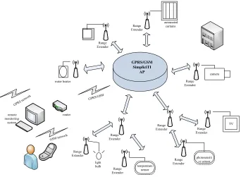
The system includes wireless LAN, remote PC monitoring and user smart phone monitoring. The system frame is shown in Figure 1.
temperature sensor
photosensiti ve sensor
TV GPRS/GSM
SimpliciTI
AP camera
water heater
router remote
monitoring system
GSM network
GPRS network
light bulb
GPRS/GSM
Range Extender
automated curtains
Range Extender
Range Extender
Range Extender Range
Extender Range Extender Range Extender Range
Extender
Range Extender
Fig. 1. The system architecture diagram
3.1 System hardware design
Bluetooth module
The main controller
(STM32F103) Bluetooth module Bluetooth module
The wireless sensor (CC1110)
AP
The wireless sensor (CC1110)
ED
The wireless sensor (CC1110)
ER
The wireless sensor (CC1110)
ED
Relay drive circuit The terminal controller
(STM32F103) Relay drive circuit The terminal controller
(STM32F103) Infrared drive circuit
The wireless sensor (CC1110)
ED
The wireless sensor (CC1110)
ER
The wireless sensor (CC1110)
ED
Infrared drive circuit
The terminal controller (STM32F103) Relay drive circuit The terminal controller
(STM32F103) Infrared drive circuit
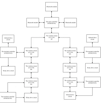
Fig. 2. Hardware system design structure
Hardware design of CC1110 wireless communication module: In the design of the system, we use ADI's ADP3300-3.3 chip as a power management chip. This chip has a wide power input range, it can reach 3 ~ 12V, and the output voltage is 3.3V [3]. Regardless of the use of batteries, USB or other means of power supply, the basic can meet the CC1110 power requirements. In the radio frequency (RF) transceiver mod-ule of the inside CC1110 chip, it contains a modem. In addition to the high sensitivity of the configuration function, it also supports a variety of modulation methods, and has a very high data transfer rate, and the maximum can reach 500kb / s [3]. The error correction of the modem can effectively reduce the bit error rate of digital signal transmission and improve the reliability of signal transmission.
sleep timer. The radio frequency matching circuit is mainly used to match the RF module input / output impedance, so that the input / output impedance is 50. Thus, it can provide the required DC bias voltage for the low noise amplifiers and power am-plifiers inside the CC1110 chip. The system uses BALUN circuit to achieve imped-ance matching function, which is composed of L122, L131, C124 and C131. The CC1110 radio frequency signal in the 433MHz band using differential signal trans-mission, and its best differential impedance is (116 + j41) [5].
Hardware design of GPRS remote wireless communication module: SIM900 communication module operating frequency is GSM / GPRS 900 / 1800MHz, the module integrates a variety of network communication protocols, including: TCP protocol, UDP protocol, HTTP protocol and FTP protocol. It can achieve the realiza-tion of voice, SMS, data and other informarealiza-tion remote transmission. The SIM900A
physical space is very compact size, and the volume is only 24 ! 24 ! 3mm. It is very
suitable for large size space requirements of a variety of smart home appliances and smart handheld terminal applications in the design. It belongs to dual frequency GSM / GPRS module, at the same time, its internal integrated a powerful ARM926EJ-S chip processor, so as to ensure the stability of the SIM900 [4].
3.2 System software design
Design of wireless LAN software system: In this section, we introduce the soft-ware design of wireless sensor network, which mainly describes the system softsoft-ware design of STM32F103 main controller and CC1110 network node.
1. The design of controller software for STM32F103
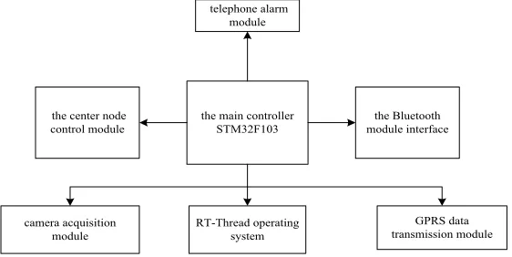
The main controller is realized by a STM32 ARM controller running RT-Thread embedded real-time operating system, which includes five functional modules, and they are image acquisition module, GPRS data transmission module, telephone alarm module, mobile phone Bluetooth interface module and the central node control mod-ule. The overall functional framework and software design process are shown in Fig-ure 3.
telephone alarm module
the main controller
STM32F103 module interfacethe Bluetooth the center node
control module
RT-Thread operating system camera acquisition
module
GPRS data transmission module
According to the functional analysis requirements, we use the modular form to achieve the functions of the various parts of the terminal controller. The terminal controller application software framework is shown in Figure 4.
the terminal controller STM32F103
the water dispenser / water
heater control module the lighting control
module the air conditioning
control module
the temperature and humidity acquisition
module
the infrared alarm monitoring module
Fig. 4. The terminal controller function frame diagram
2. The design of CC1110 wireless sensor network software
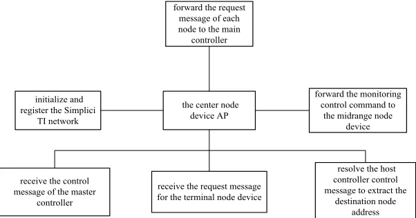
This paper mainly introduces the central node and terminal node of the design of the CC1110 wireless sensor network software. The central node equipment mainly completes the following five basic functions: (1) receiving a control message of the master controller; (2) receiving a request message for the terminal node device and the extended node device; (3) analyzing the control message of the main controller, extracting the destination address, sending the monitoring command of the main con-troller to the corresponding terminal node device and the extended node device; (4) sending a request message to the host controller for the endpoint node device; (5) initialize and register the Simplici TI network protocol. According to the central node equipment function analysis, the software design block diagram is shown in Figure 5.
the center node device AP
resolve the host controller control message to extract the
destination node address receive the control
message of the master controller initialize and register the Simplici
TI network
receive the request message for the terminal node device
forward the monitoring control command to
the midrange node device forward the request
message of each node to the main
controller
Fig. 5. The central node design block diagram
terminal controller; (5) sending an alarm message to the central node device and the extended node device. The terminal node device software design block is shown in Figure 6.
the terminal node device ED
forward the alarm request message to the
central node receive control
commands of the central node device
receive an alarm message from the terminal controller initialize and register
the Simplici TI network
forward the control command to the terminal controller
Fig. 6. Endpoint design block diagram
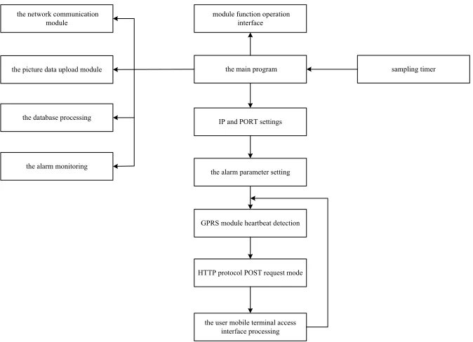
The design of the Web server software: The Web server mainly realizes the communication between the terminal hardware system and the user's mobile terminal, and stores the image data collected by the terminal hardware system in the remote database for the mobile phone client. In this software, you can check the network status, send a data transfer command, and notify the terminal to send data to the cen-ter. Respond to the query request of the mobile client and display the query result by image. The main function modules of the monitoring software design mainly include the network communication module, the image data upload module, the database module and the alarm monitoring module. The organization form is shown in Figure 7.
the network communication module
the picture data upload module
the database processing
the alarm monitoring
module function operation interface
the main program
IP and PORT settings
the alarm parameter setting
GPRS module heartbeat detection
HTTP protocol POST request mode
the user mobile terminal access interface processing
sampling timer
1. The selection and design of the servlet container
Tomcat is a very powerful SUN developed by the Servlet container, and the con-tainer is completely written in Java language. Tomcat is stable, reliable, and efficient. It is not only a Servlet container, but also can act as a Web server to use, to achieve the control platform, security domain and tomcat valve management functions [6].
Tomcat acts as a servlet container running on the server, and its primary task is to receive and resolve the client's request message, then forward the message to the corresponding servlet, and finally return the response to the client. When Tomcat acts as a servlet container, it includes three modes of operation: Servlet containers that run independently, Servlet containers in the Web server process, and Servlet containers outside the Web server process.
2. Database module design
The system uses My SQL database to manage the underlying hardware upload im-age data, and to achieve its increase, delete, change, check and other related opera-tions. The database module is the memory management module of the monitoring software. It mainly completes the establishment of the data table, performs the read and writes operation to the data table and the database maintenance function. Taking into account the ease of use of My SQL and programming requirements, all data are stored in the database format, the database access using DAO database interface.
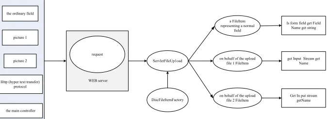
3. Photo upload server-side design
To achieve the server-side file upload, in this article, we use the Apache commons-file upload tool category. In addition, we also need a commons-io package, and then add them to the class path, and make full use of these two components. The specific implementation of the file upload block diagram is shown in Figure 8.
the ordinary field
picture 1
picture 2
Http (hyper text transfer) protocol
the main controller
ServletFileUp1oad
DiscFileItemFactory
a FileItem representing a normal
field
on behalf of the upload file 1 FileItem
on behalf of the upload file 2 FileItem
Is form field get Field Name get string
get Input Stream get Name
Get In put stream getName request
WEB server
Fig. 8. Picture upload server implementation diagram
4
Experiments
In this section, we test and validate the functional modules in the wireless sensor remote control system.
We use Servlet + JDBC technology to achieve the server, and the implementation of the program is shown in Figure 9.
browser Server Servlet + Tomcat Web
JDBC databaseMySQL
Fig. 9. Picture upload plan based on the Servlet + JDBC technology
In the test, first enter the URL in the browser search bar:
http://localhost:8080/Camera Hub/. Then, select the camera in the drop bar click to select the picture, and then click upload. Finally, click to view all the cameras. The picture upload successful indicates that the server has been successfully built and the image information upload function test passed.
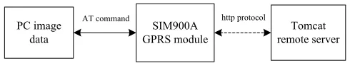
2. GPRS module image data upload server function test
In this paper, the GPRS module that we designed uses the SIMCOM Company’s SIM900A module, and through the computer's serial to debug the software. Based on the AT command of the HTTP protocol to send the GPRS module, and then send the picture data. The concrete realization scheme is shown in Figure 8.
PC image
data GPRS moduleSIM900A AT command
Tomcat remote server http protocol
Fig. 10.GPRS module picture upload function test program based on HTTP protocol
SIM900 GPRS module through the serial port connected with the PC machine string, PC through the serial port debugging tool to set the communication parame-ters: the baud rate is 115200, the data bits is set to 8 bits, the arity bit is set to "no", and the stop bit is set to "1".
Through the SIM900 GPRS module AT command to achieve HTTP network pro-tocol flow is as shown follows. Through the serial port software input instructions and parameters, each instruction followed by a new line carriage return:
AT+CSQ AT+CREG? AT+CGATT?
AT+SAPBR=3,1,"CONTYPE","GPRS" AT+SAPBR=3,1,"APN","CMNET"
AT+SAPBR=1,1 // Open the bearer to connect to the server AT+HTTPINIT // Initialize the HTTP protocol
// configure the IP address, port number, and connection directory of the remote HTTP server
AT+HTTPPARA="CONTENT","multipart/form-data;boundary=---70086703017284350872040928184"
// configure the connection parameters of the remote HTTP server, including the data type and the border character declaration
AT+HTTPDATA=7140,50000
//7140 refers to the total length of data to be sent next, here is 7140 bytes
When the module returns DOWNLOAD, enter the required data submitted by HTTP. This includes three TXT files, in the order of HTTP header files: 1.txt JPG picture of the binary data file. 2. txt and HTTP border tail file. 3. txt. It should be noted that in the second step, the data should be 2.txt COPY out and then stick to the serial debugging tool to send the area, and finally sent in hexadecimal.
AT+HTTPACTION=1 // Perform an upload operation.
AT+HTTPREAD// Displays the response information received from the server. Finally, the picture that upload to the server shows a successful upload, so far, GPRS wireless communication module upload picture data to the remote HTTP serv-er function test has been completed.
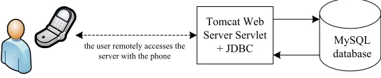
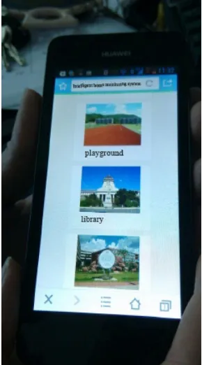
3.Mobile phone browsing remote server image information test
Tomcat Web Server Servlet
+ JDBC the user remotely accesses the
server with the phone
MySQL database
Fig. 11.The information test program of mobile phone browsing remote server image
The test program is shown in Figure 11. According to the previously deployed Tomcat Web server, here we start the HTTP server, and through the mobile terminal to access the remote server addresses:
125.89.69.239:2376/Camera Hub/cameras.jsp
The IP address is the external network IP, which supports the remote access. The results show that the phone can successfully access the URL, and normal browsing upload pictures, so the test passed, and the test results are expected to achieve the desired design goals.
Fig. 12. Mobile browsing remote server image information test results
5
Conclusions
and the popularity of 4G networks, the general image monitoring has been unable to meet the needs of most users. Therefore, the mobile video surveillance system has already become an important development trend of the intelligent home. According to the design of the remote monitoring program, we use the UDP protocol and FTP pro-tocol to realize the video communication between the mobile terminal equipment and the remote server. In addition, the system still has many shortcomings. For example, the Web services remote access interface is not friendly and beautiful, this issue should continue to improve and perfect. Due to the immaturity of power control tech-nology, the lack of encryption and other related measures, the design of the communi-cation model is relatively simple. For the large amount of data transmission and pro-cessing of video information, STM32 controller appears to be inadequate. Therefore, we should come up with a designing scheme combined the ARM and the FPGA.
6
References
[1] Adhya, S., Saha, D., Das, A., Jana, J., & Saha, H. (2016, January). An IoT based smart so-lar photovoltaic remote monitoring and control unit. In Control, Instrumentation, Energy & Communication (CIEC), 2016 2nd International Conference on (pp. 432-436). IEEE. https://doi.org/10.1109/ciec.2016.7513793
[2] Batista, N. C., Melício, R., Matias, J. C. O., & Catalão, J. P. S. (2013). Photovoltaic and wind energy systems monitoring and building/home energy management using ZigBee de-vices within a smart grid. Energy, 49, 306-315. https://doi.org/10.1016/j.energy.2012.11. 002
[3] Chang, J., & Xiao, D. (2014). Construction of intelligent home furnishing control system based on Internet of things and sensor. Journal of Chemical and Pharmaceutical Research, 6(6), 1105-1110.
[4] Fan, Z., Kulkarni, P., Gormus, S., Efthymiou, C., Kalogridis, G., Sooriyabandara, M., ... & Chin, W. H. (2013). Smart grid communications: Overview of research challenges, solu-tions, and standardization activities. IEEE Communications Surveys & Tutorials, 15(1), 21-38. https://doi.org/10.1109/SURV.2011.122211.00021
[5] GÖKBAYRAK, A. B., Kilivan, S., Akin, S., Celebi, A., & URHAN, O. (2016). Wireless sensor network-based extension to KNX home automation system. Turkish Journal of Electrical Engineering & Computer Sciences, 24(5), 3652-3663. https://doi.org/10.3906/elk-1407-47
[6] Gutiérrez, J., Villa-Medina, J. F., Nieto-Garibay, A., & Porta-Gándara, M. Á. (2014). Au-tomated irrigation system using a wireless sensor network and GPRS module. IEEE trans-actions on instrumentation and measurement, 63(1), 166-176. https://doi.org/10.1109/ TIM.2013.2276487
[7] Hafeez, A., Kandil, N. H., Al-Omar, B., Landolsi, T., & Al-Ali, A. R. (2014). Smart Home Area Networks Protocols within the Smart Grid Context. journal of Communications, 9(9), 78-86. https://doi.org/10.12720/jcm.9.9.665-671
[8] Li, M., & Lin, H. J. (2015). Design and implementation of smart home control systems based on wireless sensor networks and power line communications. IEEE Transactions on Industrial Electronics, 62(7), 4430-4442. https://doi.org/10.1109/TIE.2014.2379586 [9] Marais, J., Malekian, R., Ye, N., & Wang, R. (2016). A Review of the Topologies Used in
[10] Obaid, T., Rashed, H., Abou-Elnour, A., Rehan, M., Saleh, M. M., & Tarique, M. (2014). ZigBee Technology and its application in Wireless Home Automation systems: a survey. International Journal of Computer Networks & Communications, 6(4), 115. https://doi.org/10.5121/ijcnc.2014.6411
[11] Shen, W., Liu, G., Su, Z., Su, R., & Zhang, Y. (2016). Design and Implementation of Livestock House Environmental Perception System Based on Wireless Sensor Networks. International Journal of Smart Home, 10(5), 69-78. https://doi.org/10.14257/ijsh.2016.10.5.08
[12] Zahurul, S., Mariun, N., Grozescu, I. V., Tsuyoshi, H., Mitani, Y., Othman, M. L., ... & Abidin, I. Z. (2016). Future strategic plan analysis for integrating distributed renewable generation to smart grid through wireless sensor network: Malaysia prospect. Renewable and Sustainable Energy Reviews, 53, 978-992. https://doi.org/10.1016/j.rser.2015.09.020
7
Authors
Chunmei Liu is with Shenyang University of Technology, Shenyang, China.
Bin Li is with Shenyang University of Technology, Shenyang, China.
Guohong Shi is with China Petroleum Liaoyang Petrochemical Industries Co ny-lon factory, Liaoyang, China ([email protected]).