ISSN: 2231-5381
http://www.ijettjournal.org
Page 221
Wireless Remote Control Car Based on ARM7
V. Naga phanindra 1, B. Suresh Ram2 1
M.Tech, Dept of ECE, CMR College of Engineering and Technology, Hyderabad, AP-India,
2
Assoc Prof, Dept of ECE, CMR College of Engineering and Technology, Hyderabad, AP-India,
Abstract
—
Bluetooth is a wireless module which transfers data two Bluetooth devices. This module enables you to transmit & receive wireless data in serial format. It is an advanced technology which can is widely used now-a-days in mobile data sharing and within network communications like modem to printer, etc. Allowing transparent two way data communication. In our project we can simply use it for transmitting wireless serial data to establish connection between MCU or embedded project and PC. Our project is designed for surveillance applications, for which we are using a wireless camera and a Bluetooth modem for navigating the robot. Here we control the robot through PC hyper terminal or .net c# application. Bluetooth modem is connected to microcontroller serially with 9600 baud rate. The range of Bluetooth modem is 10 meters with frequency 2.4 GHz. Blue tooth Transmit power is 4dBm and sensitivity is 84 dBm. Here in our project Bluetooth modem acts as receiver and an android application acts as transmitter which is paired to the Bluetooth module. In this way we can control the robot.
Keywords
—
ARM7, Android mobile application, Bluetooth, Embedded development, LPC2148, L293D , PWM, UART , Wireless camera.I. INTRODUCTION
In recent years, the applications of mobile robot have gradually become more diverse, which makes the robot closer to people's daily life. At present, the middle and small scale motion robot are usually designed based on single chip
microcomputer without operating system, such as
FIFA/RoboCup middle and small scale football robot, bionic snake robot, multi-foot crawling robot and so on. In order to make the research results of the robot can actually be used in solving more realistic problems, the increasingly complex control process and some special application which is called for high real-time requirement has presented challenges to the existing motion robot design pattern [1]. The performance bottlenecks of the intelligent mobile robot focused on the following three aspects. The First contradiction is between the development cost and the hardware performance. In order to reduce the cost of the robot’s hardware in design, we often use cost-effective hardware to build the robot system. However, when the controls became more complex, precise increase gradually, the performance of the original hardware would be
inadequate. Rebuild the robot will not only increase the cost of inputs, but also waste the robot's life cycles seriously. The
next contradiction is between complexity ofcontrols and the
real-time performance. When the hardware performance is insufficient to complete the control of the higher complexity task, the system often sacrifices time to compensate the lack
of hardware performance. So that it brings a serious problem in real time. The third contradiction is different fields use platform is difficult to unity. When the mobile robot used in different occasions, as the users of the technology from different backgrounds, different habits, a lot of software and hardware tools due to the limited of hardware performance, or the interfaces is not enough will cause difficulties for practical use.
II. SYSTEM MODEL
To settle the problems above, we proposed the ARM7 based wireless remote control car system design scheme, which use the popular ARM7 processor architecture, a Bluetooth wireless communication module and a wireless camera We increase the efficiency of hardware resources by using ARM7 processor, use the embedded application software to make up for lack of hardware resources, which introduce a number of software tools directly to the mobile robot system to complete the complex intelligent control tasks and intelligent decision making tasks, so that we can exploit the maximum performance of hardware resources, ensure the stability of mobile robots with real-time while we make sure the control of complex tasks in the case of cost savings.
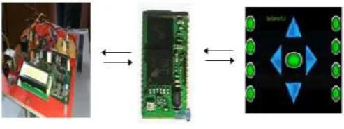
Figure 1. Overall Structure of Wireless Remote Control Car System
Figure 1 is the overall structure diagram of wireless remote control car system. According to the idea that the function decides structure, and hardware and software co design principles [3], we used the distributed structure and divided the system intothree parts:
ISSN: 2231-5381
http://www.ijettjournal.org
Page 222
provide other functions. It can also achieve some basicmechanical function with the servo and transmit the collected data to the mobile through Bluetooth. In this paper, the embedded remote control car equipped with the image sensor used to implement video capture. Figure 2 shows the logic block diagram of the embedded remote control car. The bottom layer is hardware circuit layer, which is the hardware physical implementation part of the car. We choose the ARM7 development board as the control centre which connects motors of the robot through L293D [H-Bridge], used for peripheral motion control circuit through the appropriate interfaces. Some peripheral devices related with the motion control can also be connected to the motion control circuit which controls the movement of remote control car by changing the motor’s parameters. The layer above hardware circuit layer is the Bluetooth module which works on serial communication RS-232 protocol UART to receive commands from the remote mobile phone with smart Android Application.
Figure 2. Block Diagram of Embedded Car
Figure 3. Blue control Android Application
Blue Control is a basic universal Remote Control for Blue-Tooth enabled serial devices such as Blue Blue-Tooth modules connected to a micro-controller. For each button pressed the corresponding ASCII code for the label will be sent. For example pressing buttons A-H will send the characters "a" - "h". The up, down, left, right, and centre buttons will send
"U","D","L","R", and "C" characters. Hopefully this will inspire people to create a lot of fun Blue-Tooth Controlled devices.
Figure 4. Wireless camera Communication Diagram
Technical Parameters of Transmitting Unit
Video Camera Parts: 1/3" 1/4" Image Sensors
System: PAL/CCIR NTSC/EIA
Effective Pixel: PAL: 628X582 NTSC: 510X492
Image Area: PAL: 5.78X4.19mm NTSC:
4.69X3.45mm
Horizontal Definition: 380 TV Lines
Scanning Frequency: PAL/CCIR: 50HZ
NTSC/EIA: 60HZ
Minimum Illumination: 3LUX
Sensitivity: +18DB-AGL ON-OFF
Output Electrical Level: 50MW
Output Frequency: 1.2G/2.4G
Transmission Signal: Video, Audio
Linear Transmission Distance: 50-100M
Voltage: DC+9V
Current: 300mA
Power Dissipation:<=640MW
Technical Parameters of Receiving Unit
Wireless Audio Receiver
Receiving Method: Electronic Frequency
Modulation
Reception Sensitivity: +18DB
Receiving Frequency: 1.2G/2.4G
Receiving Signal: Video, Audio
Voltage: DC 12V
Current: 500mA
ISSN: 2231-5381
http://www.ijettjournal.org
Page 223
task processing and control decision part to the PC console.PC has many advantages include low cost of hardware, processor capacity strong, storage space large and we can use software tools which can’t be used in the embedded equipment to do data processing and decision analysis, such as Matlab. Mobile robot sent the collected data to PC for processing and decision-making through wireless network and mobile send the results back to the mobile robot for executing. In another words, complex control process and decision-making process is done by the mobile, but not the mobile robot. In this way, Mobile Robot can do anything as long as it can be done by mobile. Furthermore, no matter what kind of software tools and intelligent algorithms, as long as the mobile can use, it can be directly applied in mobile robot application. This thoroughly solved the problem that the mobile robot was constrained by technical background and usage in different application area and greatly enhances the complexity of the task which low cost mobile robot can complete
.
II. HARDWAREDESCRIPTION
The hardware architecture of the main part of the system is shown in Figure 4. The embedded remote control car circuit is exhibited in the right part of figure 4, using the mini2440 development board produced by Friendly ARM company, the USB camera and USB wireless network card are connected with the development board, the main control board also provides a plentiful high-speed peripheral interfaces, GPIO interfaces and system bus interfaces for practical application increasing the variety of remote control car module, in specific circumstances, if needed. The left part of figure 4 shows the architecture of the motion control circuit, the board selected the Uptech Robotics Multiplex board, as it uses ATmega128 MCU as microcontroller, four groups with the PWM I/O interface control the movement of two driven wheels, each driven wheels is driven by a DC brush motor. Motion control board provides 7 analog input interfaces, The motion control circuit communicates the main control circuits through the 5 Pin RS232 interface, the motion control programs is written through the ISP interface.
A.PWM Signals
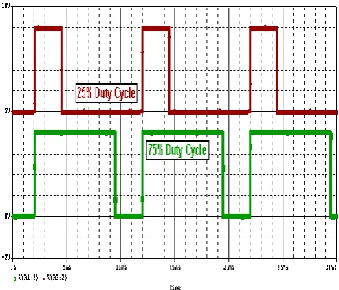
Pulse Width Modulation (PWM) is a process which changes the pulse width of a signal, while keeping the frequency/period constant. The result is a signal that may be switched HIGH for a longer or shorter amount of time than it is switched LOW. When a PWM circuit alters the pulse width in this way, it is said to be changing the duty cycle of the signal, which is the ratio of the pulse width time over the total period. Duty Cycle is a dimensionless quantity that is stated as a percentage. Figure B3 shows two examples of pulse width modulated signals.
Figure 5: Pulse Width Modulated Signals
Figure 6: The Hardware Structure Diagram
ISSN: 2231-5381
http://www.ijettjournal.org
Page 224
III. BLUETOOTHDESCRIPTION
BTM-5 module is a Class 2 Bluetooth module using BlueCore4-External chipset from leading Bluetooth chipset supplier Cambridge Silicon Radio. This module both support Master and Slave mode operation, it can be easily changed by AT command configuration. It is highly recommend using BTM-5 pair to communicate with each other. User can also use the module with the Laptop, PDA, Mobile Phone and etc.
Figure 7. Bluetooth module
The remote control car main program is an application program running on a ARM7 development board, which mainly responsible for connection of the Bluetooth console, sending the collected data to the console, receiving the instruction of the PC Console, sending the motion related instructions to the motion control circuit.
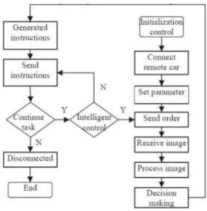
Figure 8. The Program Flow Diagram On Embedded Car Side
Motion control program is taking in charge of all the motion control of the remote control car. The specific process is shown in Figure 8, after power on, the development board and motor control board begin initializing their own program, after the main control board setting up the IP address to connect with the console, it would receive orders from the console to execute, through the Socket, if it is not a motion instructions (such as data collecting, data sending, data preprocessing, etc.), then it performs the corresponding work, until the console has no more requires available. The main control program sent the motion instruction to the motion control board through UART, the motion control.In the situation of the no automatic decisions, the operator could send motion instructions to control the movement of the remote control car manually. When the task ends, disconnecting from the console connection with the remote control car. The specific process is shown in Figure 9.
Figure 9. The Program Flow Diagram Of PC Console
V.
RESULTS & DISCUSSIONSISSN: 2231-5381
http://www.ijettjournal.org
Page 225
Figure 11. video monitoring through wireless camera in pcFigure 10 is the embedded remote control car. After platform construction is completed, we integrated test the whole system through a simple gesture recognition experiments. Figure 8 shows the interface of the system console. Due to the obstacle refraction will affect the wireless signal strength the wireless communication distance is approximate 13 meters indoor and about 180 meters outdoor in open area. Video frame rate is 8.62fps-13.16fps (as the wireless signal status). The average recognition time of gesture recognition is 1.52 seconds, the system real-time within an acceptable range.
VI. CONCLUSION
We designed and implemented a wireless remote control car system based on ARM7 in this paper. And we suggested a solution which ensures the last few tens of meters communication between the remote control cars through the secure wireless communications. We connected the remote control car to wireless mobile application. This can break the robot platform hardware performance bottlenecks, and apply the complex, sophisticated algorithms of intelligent robots to real life. Eventually, we verify the feasibility of the final design through a simple gesture recognition experiments. According to the actual needs, the algorithm in the system can be extended to complete pattern recognition, automatic obstacle avoidance, motion planning, intelligent wireless monitoring and control and other fields of application in real life.
REFERENCES
[1] Volker Graefe and Rainer Bischoff. From Ancient Machines to Intelligent Robots -A Technical Evolution[C]. The Ninth International Conference on Electronic Measurement & Instruments.
2009. Vol.3, 418-431.
[2] Liggesmeyer P., Trapp M.. Trends in Embedded Software Engineering[J]. IEEE Software, 2009, 26(3):19-25.
[3] E. D. Lagnese and D. E. Thomas, Architectural partitioning for system level design[C], in Proc. 26th DAC. June 1989, 62-67.
[4] ATMEL Corporation. ATmega128 Preliminary Summary [EB/OL]. (2010-06-21) [2011-01-13].
http://wenku.baidu.com/view/9a4bb6fb84 ae45c3b358c5d.html.
[5] Kar-Keung D. Young, Yong Quan Ou, Lun Huai Cai, Jason Kam On Ho and Ken Kin Man Cheng. Real Time Embedded Control System
Development for Wireless Mobile Platforms[C]. Industrial Electronics, 2008.
ISIE 2008. IEEE International Symposium on 2008.11.18,2022-2027.