Synthesis and Rendering of 3D Textures
Yacov Hel-Or
Tom Malzbender
Dan Gelb
School of Computer Science
Hewlett-Packard Laboratories
The Interdisciplinary Center
1501 Page Mill Road
Kanfey Nesharim St., Herzeliya, Israel
Palo Alto, CA., U.S.A.
Abstract— We extend the machinery of existing texture synthe-sis methods to handle texture images where each pixel contains not only RGB values, but reflectance functions. Like conventional texture synthesis methods, we can use photographs of surface textures as examples to base synthesis from. However multiple photographs of the same surface are used to characterize the surface across lighting variation, and synthesis is based on these source images. Our approach performs synthesis directly in the space of reflectance functions and does not require any intermediate 3D reconstruction of the target surface. The resulting synthetic reflectance textures can be rendered in real-time with continuous control of lighting direction.
I. INTRODUCTION
The characterization of real world textures and surfaces is an important aspect of enabling photorealistic rendering. Powerful texture synthesis methods were developed in the late 80’s and 90’s that are able to synthesize new texture samples from photographic examples (e.g.[1], [2], [3], [4], [5]). These methods have practical ramifications for 3D computer graphics since they can simplify the texture mapping process in several ways. First, larger patches of a texture can be produced, yielding more source material for the texture mapping process. Second, textures may be synthesized with periodic boundary conditions, producing textures that can be seamlessly tiled, with the high image quality of photographs.
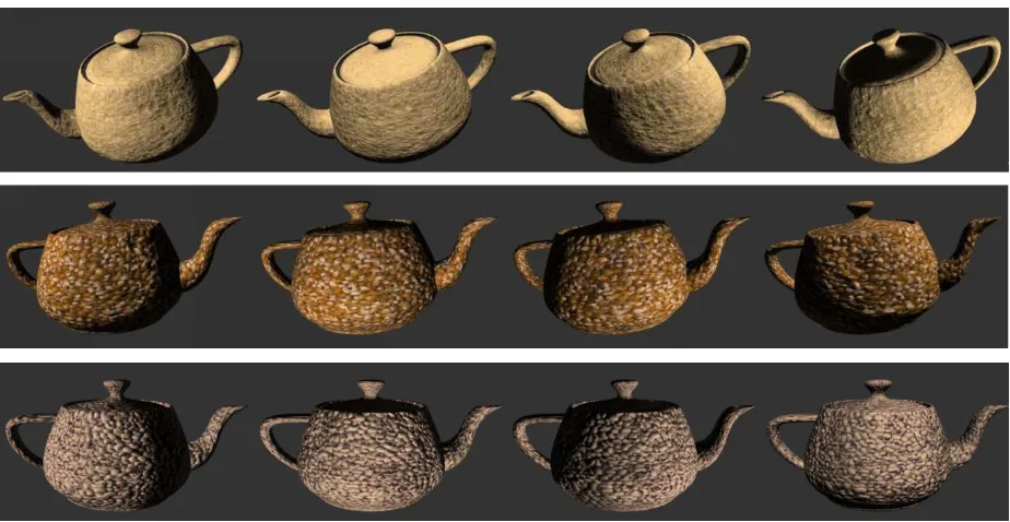
Although powerful, these texture synthesis methods have limitations that we address in this paper. Since the example photographs used as input to the texture synthesis algorithms are captured under specific lighting conditions, the synthe-sized textures have these same lighting conditions ’baked in’. Although the results will be convincing when those lighting conditions match the lighting conditions that the texture patch finds itself on the 3D object, in general this will not be the case. Due to the surface microstructure, the modifications in surface appearance due to 3D object geometry are poorly approximated by attenuating the surface intensity. Figure 2 demonstrates this behavior, when rendering results using a light-dependent texture model are compared to the rendering of the same texture modeled without lighting dependency.
Image-based re-lighting methods [6], [7], [8] provide a so-lution to this quandary. In this approach, multiple photographs of a surface, person or object are taken under varying lighting conditions and viewing directions, and a reflectance model characterizing the surface appearance is constructed. Using this model very realistic renderings of the original can be produced under arbitrary lighting and viewing conditions.
In this paper we demonstrate how the image-based re-lighting methods can be directly leveraged for the purposes of synthesizing light dependent textures. These synthetic textures can be produced having the practical advantages of tileabil-ity and photorealism that texture synthesis methods provide, combined with the lighting control of image-based reflectance functions. The main advantage of the suggested approach is that no intermediate 3D reconstruction is needed for synthesis and the process is applied directly to the image domain.
II. SURFACEREFLECTANCECHARACTERIZATION
The reflectance properties of a textured opaque material can be exhaustively specified by its Bidirectional Texture Function (BTF) introduced in [9]. The BTF measures the ratio of radiance L exiting a surface at direction (φe, θe), to the incidence irradianceIstriking the surface in a differential solid angle from direction(φi, θi):
BT Fr,g,b(φi, θi, φe, θe, u, v) =dL(φe, θe, u, v)
dI(φi, θi, u, v)
where the spatial variation is indexed by(u, v). The BTF can efficiently specify 3D texture surfaces, whose characteristics arise from spatial variations of both albedo and surface normal. Thus, the BTF function can implicitly characterize appear-ance effects such as shading, shadows, self occlusions, inter-reflections, mutual shadowing, etc. However, storage require-ments for the BTF can be prohibitive for real-time computer graphics applications, due to the high dimensionality (6 d.o.f.). In this paper we restrict ourselves to a less general, but more tractable representation we called the Unidirectional Texture Function, or UTF. Unlike the BTF, the UTF includes a dependence on only one direction, namely that of the incident light:
U T Fr,g,b(φi, θi, u, v)
III. PREVIOUSBTF/UTF TEXTURESYNTHESIS
There has been extensive work in the area of 2D texture synthesis (e.g. [1], [2], [3], [10], [4], [5]. However, the synthesis of reflectance textures from examples is conceptu-ally different from the 2D texture synthesis. A collection of images of a particular surface acquired under various lighting conditions cannot be treated as an independent collection of 2D textures. There are strong correlations between the sampled images, as all of them are instances of a unique underlying physical surface. These correlations have to be maintained while synthesizing a novel reflectance texture.
Relative to the volume of previous work in the area of 2D texture synthesis, there are only a handful of papers relevant to the synthesis of reflectance textures. Note, that the synthesized and the example textures have 4D reflectance functions assigned to each pixel. Working explicitly with this data is computationally prohibited. Thus, some sort of dimensionality reduction prior to synthesis must be applied.
Liu et. al. [11] use a texture’s height-field along with an albedo map as an intermediate representation for BTF. This representation is reconstructed from the texture examples, us-ing shape-from-shadus-ing techniques. Then, a synthesis scheme is applied directly to the height-field, using non-parametric sampling [1], resulting in a representation of a novel texture from which a new BTF is derived. Leung and Malik [12] suggests using the 3D texton map as a basis for generating a novel 3D texture. This approach is similar in spirit to [11] where a texton map is used as an intermediate compact representation. The texture’s BTF can be derived from this representation similarly to the height-field map. Tong et. al. [13] also use the texton map representation as a basis for synthesis directly on a 3D object.
All previously suggested methods use an intermediate com-pact representation for BTF, which requires some sort of 3D reconstruction. In Addition to the fact that this reconstruction is computationally intensive, it incorporates inaccuracies in the synthesized textures since accurate 3D reconstruction of complicated textures (such as fur, sponge, etc.) is impractical. This paper suggests a new technique for 3D texture syn-thesis, which takes advantage of the image-based re-relighting methods. The texture synthesis works directly with the ac-quired data with no intermediate 3D models. Our texture rep-resentation is that of a UTF modelled with polynomial texture maps (PTM) [7]. By sacrificing the view dependence of a BTF we gain a compact texture representation well matched to the rendering process, but also directly employed for synthesis. The PTMs, produced by our synthesis method can be then used in place of conventional texture maps and applied to 3D objects, providing interactive and realistic control of lighting effects, such as shading, self shadowing, interreflections, and surface scattering.
IV. BLOCKBASEDTEXTURESYNTHESIS
Viewing a texture image as a realization of a homogenous Markovian process implies that the color distributions of a texture block W are completely characterized by its causal
neighborhood NW, and that this characterization is spatially invariant (Figure 1). Therefore, the conditional probability P(W|NW) completely determines the texture characteristics. In this paper we build on a collection of techniques, which are referred to as block-based texture synthesis [3], [14]. In these methods, the Markovian process parameters are not estimated but rather the process is emulated by sampling directly from the example texture. Hence, a realization of the conditional probability P(W|NW) is achieved by randomly choosing a block from amongst all blocks Wi in the texture example satisfying: X
u,v
kNW −NWik2< δ
where δ is a predefined threshold, as shown in Figure 1. In the works of [3] and [14] blocks of texture are copied from the source images into the synthesized texture, based on the similarity of their neighborhoods. Overlapping block regions are either alpha blended or optimal boundary cuts are calculated between each neighboring blocks, so that block stitching looks smooth.
W
W
1W
2N
N
w wFig. 1. Copying blocks with similar causal neighborhoods
This paper extends the block-based method from working on images containing color values, to ’images’ of reflectance functions. We view a UTF image as a texture of functions rather than a texture of values. Thus, a UTF image is regarded as a realization of a Markovian process in the spatial domain. However, the stochastic process is performed over functions rather than over values. According to this view, a function index ψ = Ψ{g(φ, θ)} is assigned to each pixel reflectance function g(φ, θ), and the function index, ψ, is regarded as a random variable, over which a stochastic process is defined.
A Markovian process over functions implies that the distri-bution of functions attached to a texture block W is charac-terized by the conditional probability:
P(Ψ{W}|Ψ{NW})
representation of reflectance functions from a finite set of texture images, each at a specific lighting condition? Second, how can we attach an index for each possible reflectance function? The Polynomial Texture Maps or PTM [7] which was developed for image-based re-lighting purposes can give the solutions for these two questions.
V. PTMS
Polynomial texture maps [Malzbender 01] provide a com-pact representation for reflectance functions. In this approach, a real-world surface is photographed multiple times with a fixed digital camera under varying illuminations directions
{(l(i)u , l(i)v )}Ni=1 providing N images: {L(i)(u, v)}Ni=1, where
(lu, lv)denotes the projection of a unit vector whose direction is (φ, θ) onto the(u, v) plane. The PTM representation of a texture patch describes, independently for each pixel(u, v), the luminance variation,L, as a function of(lu, lv). The luminance is modeled by biquadradic polynomial function inlu, lv:
L(u, v;lu, lv) = a0(u, v)l2u+a1(u, v)l2v+a2(u, v)lulv
+ a3(u, v)lu+a4(u, v)lv+a5(u, v)
where the parameters (a0..a5) are chosen to best fit the acquired image values, thus minimizing:
X
i
kL(u, v;l(i)
u , lv(i))−L(i)(u, v)k2
Once the coefficients (a0..a5) are estimated for each pixel, renderings of the surface for arbitrary lighting direction can be computed in real time using either pure software, or pro-grammable graphics hardware acceleration, to map them onto 3D surfaces in a manner similar to conventional texture map-ping. The biquadratic polynomial as the interpolation function is not mandatory and other bases are possible as well. Note, however, that the PTM basis functions are closely related to the low degree spherical harmonics, which are optimally spanning Lamberian surfaces illuminated under various directions [15], [16].
VI. 3D TEXTURESYNTHESIS USINGPTM
Going back to block-based 3D texture synthesis, PTM coefficients can be efficiently used as the reflectance function indices over which texture synthesis is applied. Thus, a similar block-based synthesis scheme can be applied directly to the 6 dimensional vector field (a0..a5). However, care must be taken: In the 2D texture synthesis, the conditional probability P(W|NW) is achieved by sampling similar blocks in the source texture, where similarity is defined based on the values in the causal neighborhoods (Equation 6). This scheme cannot be automatically applied to function indices in the reflectance texture case. The transformation from function space to in-dex space does not necessarily preserve function distances, namely:
Z Z
kg1(lu, lv)−g2(lu, lv)k2dludlv6=kψ{g1} −ψ{g2}k2
for any given two functions g1, g2. This implies also that function pdf’s are not preserved, and in our case: P(W) 6=
P(ψ{W}). Therefore, instead of using the original coefficients of the PTM, we linearly transform the coefficients so that an orthogonal basis is used. Since orthogonal transformation is distance preserving, distance between two functions can be measured directly in the index vectors, and consequently, function probability and its corresponding index probability can be used indistinguishably.
In our implementation we have used the 2D Legendre polynomial basis, which is orthogonal over [−1,1]2. The 6 basis functions used in the standard PTM (Eq. 8), A =
{l2
u, l2v, lulv, lu, lv,1} were transformed into the orthonormal basisB:
B=
(
1 2,
√
3 2 lu,
√
3 2 lv,
3 2lulv,
√
45 4 l
2 u−
√
45 12 ,
√
45 4 l
2 v−
√
45 12
)
Ifa= [a0..a5]are the original PTM coefficients, the new basis coefficients, b= [b0..b5], are easily calculated by applying a matrix multiplication b = Ma, where M is a 6x6 matrix (see [17] for the matrix values). Using the new coefficients, each pixel(u, v)has an associated index which is constructed by the 6 dimensional vectorψ{L(u, v)}= [b0..b5]u,v. Using this indexing, a realization of the conditional probability can be achieved by randomly choosing a block from amongst all blocksWi in the texture example satisfying:
X
u,v
kψ{NW(u, v)} −ψ{NWi(u, v)}k2< δ
Edge handling between synthesized blocks is performed also in the orthogonal representations. In our case, the coefficients in the common boundaries were alpha blended. Since PTM functions are represented in an orthonormal space, coefficient blending is equivalent to blending the reflectance functions with similar weights. In a similar manner optimal cut along the common boundaries should be performed in the orthonormal basis as pixel comparisons are meaningful. At the final stage of the synthesis, an inverse transformation is performed to the standard PTM representation.
VII. SEARCHSTRATEGY
The main burden of block based texture synthesis is the search required for each generated block in the synthesized PTM. For each such block, a full search is performed in the source PTM, i.e. the distance must be computed between the block neighborhood and each of then×nneighborhoods of the source PTM image. Naively applying this search is time con-suming. Several approaches have been suggested to expedite this search. Among them, multiscale search [14], tree structure vector quantization [10], and k-coherence search [13]. All these approaches improve run time by orders of magnitude at the expense of approximating the search results. A rejection scheme, proposed in [18], can dramatically improve run time, without sacrificing the resulting accuracy. In this approach, highly dissimilar block neighborhoods in the example PTM are rejected quickly.
block neighborhood is composed ofppixels, its associated 1D vector is a6pdimensional vector, because each pixel includes 6 PTM coefficients. Using this notation, the error distance between two block neighborhoods NW1 andNW2 is defined
as:
d(NW1, NW2) =kNW1−NW2k2= k
X
i=1
[NW1(i)−NW2(i)]2
(1) wherek= 6p. However, it is possible to reject a neighborhood before evaluating allk= 6psums if the error distance already exceeds a threshold δ. This threshold can be set ahead of time or can simply be the actual error distance to the best neighborhood evaluated so far. Equation 1 is still valid when NW1 andNW2 are represented in a different orthogonal basis,
ˆ
NW1,NWˆ 2. Thus,
d(NW1, NW2)≥ `
X
i=1
[ ˆNW1(i)−NWˆ 2(i)]
2 (2)
for any `≤6p. If we choose a basis that concentrates vector energy in the first few entries, we can achieve a tight lower bound with very few calculations. Such a representation can be calculated by applying the Singular Value Decomposition on the entire neighborhood ensemble, or by using a basis set which is known to have energy compactness for natural images, such as the DCT basis, the Harr Wavelets or the Walsh Hadamard which can be computed very efficiently [18].
Using this lower bound (eq. 12), a very fast search scheme can be applied as follows: First, each neighborhood vector in the example PTM is projected onto the first basis-vector U1, resulting in ann×narray of scalar values (applied only once). Given a new block neighborhood,NW, from the synthesized image, we projectNW ontoU1, and calculate a lower bound on the neighborhood distance for each neighborhood in the example PTM using eq. 2 (where ` = 1). Note, that this lower bound is achieved by applying a single subtraction and a single multiplication per example neighborhood. Each neighborhood, whose lower bound is above the thresholdδ, is rejected and discarded in further calculations. Typically, 90% of the neighborhoods are rejected after the first projection. For the resulting neighborhoods we continue with the second basis-vector U2, increasing the lower bound, and rejecting additional neighborhoods. This process continues with con-secutive basis-vectors. After very few projections (around 3), only a few candidates remain, for which the actual distances are calculated. A typical run time for synthesis of a 512x512 patch composed of 30x30 blocks is approximately 3-5 minutes using this approach, compared to 30-60 minutes for the brute force search.
VIII. RESULTS
Figures 2-4 show results of reflectance texture synthesis from photographic examples collected under 50 light direc-tions. Figure 3 shows a single source photograph along with synthesis results under varying lighting. Figures 4 demonstrate various synthesized reflectance textures applied to 3D objects,
also under a number of lighting directions. These objects can all be illuminated and viewed in real-time. Figure 2 shows the difference between 3D texture mapping, and the conventional texture mapping.
IX. CONCLUSION
We have presented a texture synthesis method that results in the construction of images of reflectance functions instead of simply color values. This synthesis is performed directly using the representation of polynomial texture maps, thus the resulting texture maps can be rendered in real time on modern graphics hardware with parametric control over lighting direction. At the heart of our approach is the ability to compare pixels of reflectance functions directly in place of comparing pixel RGB values. This same approach allows any texture synthesis method that compares pixel colors to be extended in the analogous manner to support the synthesis of reflectance function textures.
REFERENCES
[1] A. Efros and T. Leung, “Texture synthesis by non-parametric sampling,” in IEEE ICCV, Corfu, Greece, 1999, pp. 1033–1038.
[2] D. Heeger and J. Bergen, “Pyramid-based texture analysis/synthesis,” in
ACM SIGGRAPH, 1995, pp. 229–238.
[3] A. Efros and W. Freeman, “Image quilting for texture synthesis and transfer,” in ACM SIGGRAPH, 2001, pp. 341–346.
[4] J. Portilla and E. Simoncelli, “A parametric texture model based on joint statistics of complex wavelet coefficients,” IJCV, vol. 40, no. 1, pp. 149–71, Dec. 2000.
[5] J. Debonet, “Multiresolution sampling procedure for analysis and syn-thesis of texture images,” in ACM SIGGRAPH, 1997, pp. 361–368. [6] P. Debevec, T. Hawkins, C. Tchou, H. Duiker, W. Sarokin, and M. Sagar,
“Acquiring the reflectance field of a human face,” in ACM SIGGRAPH, 2000, pp. 145–156.
[7] T. Malzbender, D. Gelb, and H. Wolters, “Polynomial texture maps,” in
ACM SIGGRAPH, 2001, pp. 519–528.
[8] M. Ashikhmin and P. Shirley, “Steerable illumination textures,” ACM
Trans. on Graphics, vol. 21, no. 1, pp. 1–19, Jan. 2002.
[9] K. Dana, B. Ginneken, S. Nayar, and J. Koenderink, “Reflectance and texture of real-world surfaces,” ACM Trans. on Graphics, vol. 18, no. 1, pp. 1–34, Jan. 1999.
[10] L. Wei and M. Levoy, “Fast texture synthesis using tree-structured vector quantization,” in ACM SIGGRAPH, 2000, pp. 479–488.
[11] X. Liu, Y. Yu, and H. Shum, “Synthesizing bidirectional texture func-tions for real-world surfaces,” in ACM SIGGRAPH, 2001, pp. 97–106. [12] T. Leung and J. Malik, “Represention and recognizing the visual
appearance of materials using three-dimensional textons,” IJCV, vol. 43, no. 1, pp. 29–44, Jan. 2001.
[13] X. Tong, J. Zhang, L. Liu, X. Wang, B. Guo, and H. Shum, “Synthesis of bidirectional texture functions on arbitrary surfaces,” in ACM
SIG-GRAPH, 2000, pp. 665–672.
[14] L. Liang, C. Lieu, Y. Xu, B. Guo, and H. Shum, “Real-time texture synthesis by patch based sampling,” ACM Trans. on Graphics, vol. 20, no. 3, pp. 127–150, 2001.
[15] R. Ramamoorthi, “nalytic pca construction for theoretical analysis of lighting variability in images of a lambertian object,” IEEE T-PAMI, vol. 24, no. 10, Oct. 2002.
[16] R. Basri and D. Jacobs, “Lambertian reflectence and linear subspaces,”
IEEE T-PAMI, vol. 25, no. 2, Feb. 2003.
[17] Y. Hel-Or, T. Malzbender, and D. Gelb, “Synthesis of reflectance function textures from examples,” HP Labs, Tech. Rep. HPL-2003-16R1, 2003.
Fig. 2. Bottom: Synthetic sponge material with varying reflectance function per textel. Top: Synthetic sponge without reflectance functions (conventional texture map).
Fig. 3. Left: Section of original source image under one lighting condition. Right: Synthetic texture under varying lighting directions.