Available Online at www.ijpret.com 1617
INTERNATIONAL JOURNAL OF PURE AND
APPLIED RESEARCH IN ENGINEERING AND
TECHNOLOGY
A PATH FOR HORIZING YOUR INNOVATIVE WORKADDITIVE WAVELET BASED IMAGE FUSION USING A TROUS WAVELET
DECOMPOSITION AND IMPROVED NONLINEAR IHS TRANSFORM
MAHESH P. CHAKKARWAR1, PROF A. V. DEORANKAR2, DR. P. N. CHATUR3
1.M. Tech. Scholar, GCOE, Amravati.
2.Head of Information Technology Dept., GCOE, Amravati.
3.Head of Computer Science & Engineering Dept., GCOE, Amravati.
Accepted Date: 05/03/2015; Published Date: 01/05/2015
Abstract:Satellite sensors are diverse in their properties, as sensors generating images with high spectral resolution have low spectral resolution and vice versa. Several methods have been proposed so far, not touched out of gamut problem of creating new colors which falls out of RGB cube. Existing methods solve the out of gamut problem by color clipping that leads to color distortion and contrast reduction. In this paper improved nonlinear IHS conversion is used, so that all the out of gamut pixels falls into RGB cube without using color clipping technique. But, but due to the large intensity difference between Multispectral (MS) and Panchromatic(PAN) image, saturation value expands to its maximum value that leads to color distortion. The solution to the problem is rather than direct intensity substitution; add only spatial information from PAN image to MS. In this paper wavelet based additive wavelet using a trous wavelet decomposition is proposed to solve color distortion due to the large intensity difference.
Keywords: Non Linear, IHS Transform
Corresponding Author: MR. MAHESH P. CHAKKARWAR
Access Online On:
www.ijpret.com
How to Cite This Article:
Mahesh P. Chakkarwar, IJPRET, 2015; Volume 3 (9): 1617-1626
Available Online at www.ijpret.com 1618
INTRODUCTION
IKONOS and Quick Bird are the satellites uses image fusion techniques to generate images with high spatial and spectral resolution that can be used for feature extraction, land cover classification and visual inspection etc. Many techniques proposed so far for image fusion such as IHS (Intensity, Hue, and Saturation) [1]-[2], Independent Component Analysis (ICA) [3], Principle Component Analysis (PCA), Wavelet Transformation[5] etc. These methods not touched gamut problem that arises when transformed color falls out of RGB cube.
Nonlinear IHS image Fusion Technique:
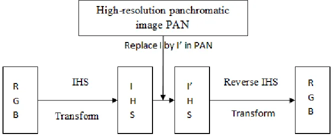
In nonlinear IHS image fusion technique, each pixel in RGB image is mapped to IHS color space where each component of pixel such as Intensity, Hue and Saturation are intuitively manipulated separately. The basic model for nonlinear IHS image fusion is given as below [6];
Fig. 1 Illustration of Image Fusion using IHS Transformation using intensity substitution
The nonlinear IHS model also called HSI model is nothing but direct scaling operation in the RGB cube by doing 𝑖′ = 𝑖 × 𝛾 is given as fallows[7];
𝑟′ 𝑔′ 𝑏′
=
𝑖′(1 − 𝑠)
𝑖′[1 + 𝑠𝑐𝑜𝑠()/cos(60° − )]
3𝑖′ − (𝑟′ + 𝑔′)
= (𝑖′/𝑖)
𝑟 𝑔 𝑏
= 𝛾 𝑟 𝑔 𝑏
Improved Nonlinear IHS transform:
Available Online at www.ijpret.com 1619 1) Conversion of RGB to improve nonlinear IHS transformation is defined as fallows [7];
The boundary surface 𝐵𝑆𝑖𝑁𝐼𝐻𝑆 two halves is given as;
𝑖 =2
3−
𝑚𝑜𝑑 120 −60
180 ;
The algorithm for RGB to iNIHS is as fallows;
𝐼 =(𝑅 + 𝐺 + 𝐵)
3
𝑎 = (2𝐵 − 𝐺 − 𝑅)/2
(𝐵 − 𝐺)2+ (𝐵 − 𝑅)(𝐺 − 𝑅)
𝐻 = cos
−1 𝑎 𝑖𝑓 𝐺 ≥ 𝑅
2𝜋 − cos−1 𝑎 𝑖𝑓 𝐺 < 𝑅
𝑖𝑓 𝑖𝑐 ≤ 2
3−
𝑚𝑜𝑑 120 −60
180 then
% Pixel C is in 𝐻𝐿𝑂𝑊𝐸𝑅
% RGB to IHS transformation
𝑆 = 1 −3min(𝑅, 𝐺, 𝐵)
𝑅 + 𝐺 + 𝐵
𝑒𝑙𝑠𝑒
% Pixel C is in 𝐻𝑈𝑃𝑃𝐸𝑅
% CMY to IHS transformation
𝑆 = 1 −3(1 − max 𝑅, 𝐺, 𝐵 )
3 − (𝑅 + 𝐺 + 𝐵)
2) Reverse of iNIHS to RGB conversion is given as [7];
a) iNIHS to RGB conversion for 𝐻𝐿𝑂𝑊𝐸𝑅
Available Online at www.ijpret.com 1620
𝐵 = 𝐼 1 − 𝑆 ;
𝑅 = 𝐼 𝑆𝐶𝑂𝑆 𝐻
𝐶𝑂𝑆 60° − 𝐻 ;
𝐺 = 3𝐼 − 𝑅 + 𝐵 ;
%SECTION GB (120° ≤ 𝐻 < 240°)
𝑅 = 𝐼 1 − 𝑆 ;
𝐺 = 𝐼 1 + 𝑆𝐶𝑂𝑆 𝐻
𝐶𝑂𝑆 60° − 𝐻 ;
𝐵 = 3𝐼 − 𝑅 + 𝐺 ;
% SECTION BR (240° ≤ 𝐻 < 360°)
𝐺 = 𝐼 1 − 𝑆 ;
𝐵 = 𝐼 1 + 𝑆𝐶𝑂𝑆 𝐻
𝐶𝑂𝑆 60° − 𝐻 ;
𝐵 = 3𝐼 − 𝑅 + 𝐺 ;
b) iNIHS to RGB conversion for 𝐻𝑈𝑃𝑃𝐸𝑅
% SECTION YC(60° < 𝐻 ≤ 180°)
𝐻 = 𝐻 − 240°;
𝐺 = 𝐼 1 − 𝑆 + 𝑆;
𝐵 = (1 − 𝐼) 1 + 𝑆𝐶𝑂𝑆 𝐻
𝐶𝑂𝑆 60° − 𝐻 ;
𝑅 = 3𝐼 − 𝐺 + 𝐵 ;
%SECTION CM 180° ≤ 𝐻 < 300° 𝑎𝑛𝑑 𝑖 >1
3+ |𝐻 − 240°|/180°;
Available Online at www.ijpret.com 1621
𝑅 = (1 − 𝐼) 1 + 𝑆𝐶𝑂𝑆 𝐻
𝐶𝑂𝑆 60° − 𝐻 ;
𝐺 = 3𝐼 − 𝐺 + 𝐵 ;
% SECTION MY −60° < 𝐻 ≤ 0° 𝑎𝑛𝑑 𝐼 > 1
3+
360°−𝐻
180 ° 𝑂𝑅 (0° < 𝐻 ≤ 60° 𝑎𝑛𝑑 𝐼 >
1 3+
/180°)
𝐻 = 𝐻 − 120°;
𝑅 = 𝐼 1 − 𝑆 + 𝑆;
𝐺 = (1 − 𝐼) 1 + 𝑆𝐶𝑂𝑆 𝐻
𝐶𝑂𝑆 60° − 𝐻 ;
𝐵 = 3𝐼 − 𝑅 + 𝐺 ;
A trous Wavelet transform:
A trous algorithm is an discrete approach of the wavelet transform. In this algorithm the decomposition is represented as parallelepiped. The original image is represented as I2j with resolution 2j with C columns and R rows. Each level of parallelepiped is approximation to the original image. When the dyadic decomposition is applied, Nthlevel of the parallelepiped has resolution 2j-N. The spatial details lost between two successive approximationsI2jand I2j-1 is collected in wavelet plane w2j-1. A trous algorithm also called shift invariant discrete wavelet decomposition as each approximation has same number of rows and columns as original image. The consequence of this algorithm is, orthogonal i.e. each approximation has redundant information to its previous approximation. The decomposition scheme is dynamically shown as below [8];
Available Online at www.ijpret.com 1622
Additive Wavelet Image fusion using a trous Wavelet Decomposition:
The steps for merging IKONOS images using additive wavelet using iNIHS transformation are as fallows;
1) Apply the iNIHS transform to the RGB composition of the multispectral image. This transformation separates the spatial information of the multispectral image into the Intensity component.
2) Generate a new panchromatic image, whose histogram matches the histogram of the Intensity image.
3) Apply a trous wavelet decomposition algorithm to the ‘histogram-matched’ panchromatic one.
4) Get first wavelet coefficient w1 by subtracting 1st level approximation from original image.
5) Apply step 3 again to get wavelet coefficient w2 by subtracting 2nd level approximation from 1st level approximation.
6) Add this spatial detail information in wavelet coefficients w1 and w2 by adding w1 and w2 to the Intensity image.
7) Apply iNIHS to RGB transform.
Available Online at www.ijpret.com 1623
Fig.2 Additive Wavelet Fusion using improved nonlinear IHS transform
Experimental Results
a. Visual Analysis
The multispectral images are downloaded from Quick Bird. Artificial dataset for image fusion i.e. multispectral (MS) and panchromatic (PAN) images are derived from given satellite multispectral image. The generation of dataset for image fusion is as fallows;
1) Let the given satellite image be I.
2) Transform the image Iinto gray image G.
3) Equalize the histogram of image G, and take the result as PAN image.
4) Down-sample I to its original resolution to get generated MS image I’.
5) Darken I’ or brighten G so that the intensity values of PAN (G) image are higher than the MS (I’).
6) Image fusion is carried out on PAN (G) and MS (I’) image.
Available Online at www.ijpret.com 1624
a) b)
c) d)
Fig. 3 a) MS image b) PAN image c) Image fusion result of a and b using intensity substitution d) Image fusion result of a and b using a trous additive wavelet.
b. Quantitative Results:
The quantitative analysis of methods of image fusion is carried out by the measures Spatial Coefficient (SC), Root Mean Square Error (RMSE), Correlation Coefficient (CC).
1. The RMSE between original MS image and fused image is given as[9];
𝑅𝑀𝑆𝐸 = (𝛿𝑚𝑠 − 𝛿𝑓𝑢𝑠𝑒𝑑)2+ (𝑚𝑚𝑠 − 𝑚𝑓𝑢𝑠𝑒𝑑)2 (0<=RMSE<=1)
Lower the RMSE value, more the correspondence between MS and Fused image.
2. The Correlation Coefficient between MS image and result of image fusion is given as;
𝑟 = 𝑥𝑖 −𝑥𝑚 𝑦𝑖 −𝑦𝑚 𝑖
𝑥𝑖 −𝑥𝑚 2
𝑖 𝑥𝑖 −𝑥𝑚 𝑖 2 (-1<=Correlation Coefficient<=+1)
Available Online at www.ijpret.com 1625 3. The spatial quality analysis is done using spatial coefficient. The filter used is Laplacian as
illustrated in the following equation[9];
−1 −1 −1
−1 8 −1
−1 −1 −1
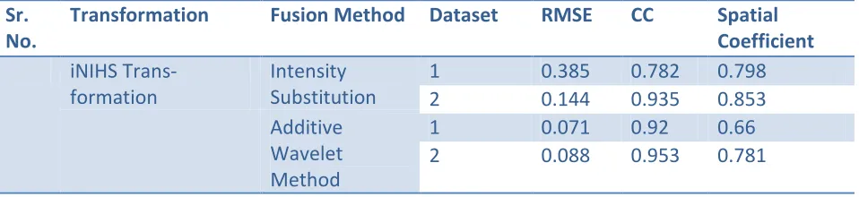
The correlation coefficient between high-pass filtered Fused image and high pass filtered PAN image is used to get spatial coefficient whose value is in the range of 0<= Spatial Coefficient <=1. More the value more spatial similarity between fused and MS image. The comparison of both image fusion methods i.e. intensity substitution and a trous additive wavelet quantitatively are as fallows;
Sr. No.
Transformation Fusion Method Dataset RMSE CC Spatial
Coefficient
iNIHS Trans- formation
Intensity Substitution
1 0.385 0.782 0.798
2 0.144 0.935 0.853
Additive Wavelet Method
1 0.071 0.92 0.66
2 0.088 0.953 0.781
Table 1 Quantitative Results of image fusion using intensity substitution and additive wavelet.
CONCLUSION
Available Online at www.ijpret.com 1626
REFERENCES
1. E. M. Schetselaar, “Fusion by the IHS transform: Should we use cylindrical or spherical coordinates?” Int. J. Remote Sens., vol. 19, no. 4, pp. 759–765, Mar. 1998.
2. Y. Kim, Y. Eo, Y. Kim, and Y. Kim, “Generalized IHS-based satellite imagery fusion using spectral response functions,” ETRI J., vol. 33, no. 4, pp. 497–505, Aug. 2011.
3. F. Chen, F. Qin, G. Peng, and S. Chen, “Fusion of remote sensing images using improved ICA mergers based on wavelet decomposition,” Proc.Eng., vol. 29, pp. 2938–2943, 2012.
4. M. Gonzalez-Audicana, J. L. Saleta, R. G. Catalan, and R. Garcia, “Fusion of multispectral and panchromatic images using improved IHS and PCA mergers based on wavelet decomposition,”
IEEE Trans. Geosci. Remote Sens., vol. 42, no. 6, pp. 1291–1299, Jun. 2004.
5. J. Nunez, X. Otazu, O. Fors, A. Prades, V. Pala, and R. Arbiol, “Multi resolution-based image fusion with additive wavelet decomposition,” IEEE Trans. Geosci. Remote Sens., vol. 37, no. 3, pp. 1204–1211, May 1999.
6. Y. Zhang, “Understanding image fusion,” Photogramm. Eng. Remote Sens., vol.70, no. 6, pp. 657–661,2004.
7. Chun-Liang Chien and Wen-Hsiang Tsai, “Image Fusion With No Gamut Problem by Improved Nonlinear IHS Transforms for Remote Sensing”, IEEE Transactions on Geoscience And Remote Sensing, Vol. 52, No. 1, January 2014.
8. M. González-Audícana, X. Otazu, O.Fors, and A. Seco, “Comparison between Mallat’s and the ‘a trous’ discrete wavelet transform based algorithms for the fusion of multispectral and panchromatic images,” Int. J.Remote Sens., vol. 26, no. 3, pp. 595–614, Feb. 2005.