Available Online at www.ijpret.com 375
INTERNATIONAL JOURNAL OF PURE AND
APPLIED RESEARCH IN ENGINEERING AND
TECHNOLOGY
A PATH FOR HORIZING YOUR INNOVATIVE WORKDESIGN AND DEVELOPMENT OF FRAME STRUCTURE FOR HYDRAULIC
PRESS WITH FEA TECHNIQUE
MR. ABHIJIT. G. NAIK1, MR. AMAY D. MESHRAM2
1. Assistant Professor, Mechanical Engineering Department, IBSS college of Engineering, Amravati, MH, India. 2. Assistant Professor, Mechanical Engineering Department, IBSS college of Engineering, Amravati, MH, India.
Accepted Date: 05/03/2015; Published Date: 01/05/2015
\
Abstract:This paper proposes a methodology for design and development of frame structure for hydraulic cotton lint bailing press with CAD (Computer Aided Design)/ FEA (finite element analysis) techniques. Structural optimization tools and computer simulations have gained the paramount importance in industrial applications as a result of innovative designs, reduced weight and cost effective products. Especially, in aircraft and automobile industries, optimization has become an integral part of the product design process Ginning is the process of separation of fiber from cottonseed. Composite ginnery performs ginning and pressing operations to convert lint cotton into a bale. In modern day, capacity of ginning plant is such that the cotton bale handled by their press system gives rise to very large forces. Frame structure like all the other equipment has to be able to withstand these forces without damage. It is essential that the calculations for mechanical strength to check the suitability of top and bottom frame. Against the structure of frame-type hydraulic press in this paper, a solid model has been built with CAD program Pro/E/ANSYS12 modeling environment and the hydraulic press frame is simulated by finite element simulation program ANSYS under static conditions for maximum load condition. This paper analyses the variation of stress, strain and frame deformation under working conditions, and the failure sections of hydraulic press frame can be found under the maximum work load at top frame.
Keywords:Failure analysis, Hydraulic press, Cotton bale. FEA, ANSYS, Frame structure, Optimization .
Corresponding Author: MR. ABHIJIT. G. NAIK
Access Online On:
www.ijpret.com
How to Cite This Article:
Available Online at www.ijpret.com 376
INTRODUCTION
Modern hydraulic presses are, in some cases, better suited to applications where the mechanical press has been traditionally more popular. [1] The hydraulic press is one of the oldest of the basic machine tools. In its modern form, is well adapted to presswork ranging from coining jewelry to forging aircraft parts. The full force of a hydraulic press can be delivered at any point in the stroke. This feature is a very important characteristic of most hydraulic presses. A mechanical press usually can exert several times the rated maximum force in the event of an accidental overload. This extreme overload often results in severe press and die damage. It is essential that the calculations for mechanical strength to check the suitability of top and bottom frame. For quality compare the weight if possible. Try to determine the character of the frame construction. If a weldment, look at the plate thicknesses, extent of ribbing, and stress relieving [2].
So in this paper successful attempt to overcome different problem of top and bottom frame, which is reported by the manufacturer. By using the Pro/E wildfire 4.0 firstly we had developed the CAD model of the top and bottom frame mechanism and than by using ANSYs software the FEM analysis of it is carried out. Due to the diversification of structural optimization problems, most structural optimization problems can be classified as size, shape and topology optimization. The main application of optimal design of steel structures is the size optimization, because this method is possible to minimize the weight of structures [4].
1.2 Hydraulically operated up packing cotton lint baling press:-
The Jadhav Zen Door-Less Bale Press is designed to be “energy efficient”. It uses a Single 2 no's x 250 mm in diameter-ram. Features include a super high capacity lint feeder and a totally enclosed right-angle gear drive tramper. A unique follow block and platen design enables square knot type wire to be applied manually and semi-automatically. Automatic strapping and wire tying systems are also applicable to the variable shut-height system. The Bale press consists of a frame, hydraulic rams, and a hydraulic power system.
1.3 Problem Identification
Reduction of bending stresses causing bending of frame by optimizing the Top & Bottom frame.
Reduction of cost and Improve safety
Available Online at www.ijpret.com 377
Designing an optimal thickness to minimize the maximum deflection.
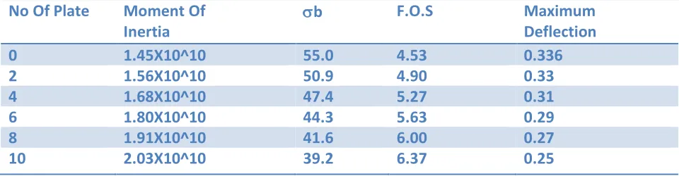
2 ANALYTICAL ANALYSIS FOR TOP AND BOTTOM FRAME WITH SHOWING THE EFFECT OF SUPPORTING PLATE (RIBS) ON FRAME
Table1 Analytical analysis for Top frame
No Of Plate Moment Of
Inertia
b F.O.S Maximum
Deflection
0 1.45X10^10 55.0 4.53 0.336
2 1.56X10^10 50.9 4.90 0.33
4 1.68X10^10 47.4 5.27 0.31
6 1.80X10^10 44.3 5.63 0.29
8 1.91X10^10 41.6 6.00 0.27
10 2.03X10^10 39.2 6.37 0.25
Available Online at www.ijpret.com 378
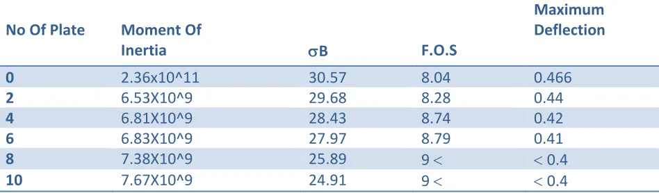
Table 2 Analytical analysis for bottom frame
3. FINITE ELEMENT ANALYSIS OF TOP & BOTTOM FRAME
The main goal of FEM is to obtain the finite element mesh, transforming the continuous structure into a discrete model, model with a finite no of points. The boundary condition and external loads are applied to this system before solving. Conventional analytical method for solving stress and strain become very complex and almost impossible when part geometry is very complex and almost impossible when part geometry is intricate. Finite element process allows discrediting the intricate geometries into small fundamental volumes called finite element. It is possible to write the governing equations and material properties for these elements. These equations when solved give the result that described the behavior of original complex body being analyzed.[6]
The process is repeated until specified convergence criterion is satisfied. Application programs developed to integrate commercially available CAD/CAM/FEA/Design optimization tools enable implementation in virtual environment and facilitate automation. The application programs can be reused for similar design problems provided that the same set of tools is used.[8]
3.1 FEA Objective:-
Primary:- Reduction of bending stresses causing bending of frame by optimizing the frame supports. Secondary: Reduction of cost & Improve safety. The whole objective is to use FEA based simulation, and determine which the best design solution for frame.
3.2 Element Selection
For most supports analysis, the element selection is made from three categories of elements:
No Of Plate Moment Of
Inertia B F.O.S
Maximum Deflection
0 2.36x10^11 30.57 8.04 0.466
2 6.53X10^9 29.68 8.28 0.44
4 6.81X10^9 28.43 8.74 0.42
6 6.83X10^9 27.97 8.79 0.41
8 7.38X10^9 25.89 9 0.4
Available Online at www.ijpret.com 379
1. ax symmetric solid elements
2. shell/plate elements
3. 3-D brick elements.
Although nearly all problems can be solved using 3-D brick elements, the other two types offer significant reductions in the solution time and effort where they are applicable, Therefore a four node quadratic shell Elements is selected.
3.3 Boundary & Loading condition
TABLE4 Boundary & Loading condition For Bottom frame
4 ANALYSIS REASULT FOR OLD FRAME
Parts force(N) due to
Punching along
upward direction
Self-weight Fix
Displacement
Weight of the Hydraulic cylinder
Top frame Old model
177000 9810mm/sec2
along downward direction
At support hinged
Available Online at www.ijpret.com 380
5 REASULT CONCLUSION FROM FEA
Equivalent stress observed that Equivalent stress >> Yield strength of material
Available Online at www.ijpret.com 381
Analytically It is found that Rectangular cross sectional top frame most suitable for Hydraulic Press. Now Optimize the Rectangular cross sectional top frame.
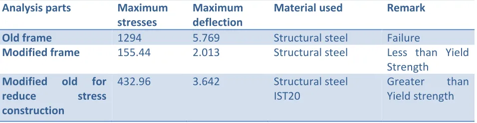
Table 5 Comparison between Last three cases
Analysis parts Maximum
stresses
Maximum deflection
Material used Remark
Old frame 1294 5.769 Structural steel Failure
Modified frame 155.44 2.013 Structural steel Less than Yield
Strength
Modified old for
reduce stress
construction
432.96 3.642 Structural steel
IST20
Greater than
Yield strength
6. FEA OPTIMIZATION
Objective function: Weight Minimization
Constraints: - Equivalent stresses i.e. Yield Strength of Material (310 Mpa) and Deformation (3 mm) [5] Parameters: - By reducing and changing No of support plate for topology optimization Method [6]and changing the thickness of plate (size optimization) Changing the Material (Design optimization)
7 REASULT & DISCUSSION
Component Current design
weight (kg)
New design
weight (kg) Weight reduction (kg) Weight reduction In Percentage FRAME WEIGHT
2146 1854 292 13
FRAME COST
Available Online at www.ijpret.com 382
8 CONCLUSIONS
The trade-off between structural performance and machining cost is highlighted using these design examples. Furthermore, the process starts with prelim information about the component and delivers optimum components at the end.
The design calculations of Hydraulic press system are playing important role as we come to know the value of total force develops in the system. The value of tensile stresses developed in the system is greater than the permissible limit. Selection of good shape provides strength to the system as the system is only undergoing through bending according to the FEA Analysis the best solution is obtained by changing the shape and design of the Top and Bottom frame structure.
REREFERENCES
1. R. Lown, "Hydraulic Presses in the 80's", Based on SME Technical Paper, MF82-918, The Society of Manufacturing Engineers, Dearborn Michigan, © 1982.
2. S Marco Evangelos Biancolini, Carlo Brutti, Eugenio Pezzuti ,"Shape Optimizations For Structural Design By Means Of Finite Elements" Method XII ADM International Conference - Grand Hotel - Rimini – Italy - Sept. 5th-7th, 2001
3. A text book "Design data hand book ,By K madhwan, Third edition, CBS Publication and distribution
Available Online at www.ijpret.com 383
5. P.E. Uys, K. Jarmai, J. Farkas "Optimal design of Hoist structure frame" Department of Mechanical Engineering, University of Miskolc, H-3515 Miskolc Egytemvanoc, Hungary Received: 10 July 2001; received in revised form 31 March 2003; accepted 9 June 2003
6. Edke, K. H. Chang "Shape optimization of heavy load carrying components for structural performance and manufacturing cost “Received: 2 May 2005 / Revised manuscript received: 8 July 2005 / Published online: 2 February 2006.
7. B.Tadic, P.M.Todorovic, B.M. Jeremic "Failure analysis and effect of redesign of a polypropylene yarn twisting machine" Department for Production Engineering, 34000 Kragujevac, Serbia. 21 March 2011