Extreme Networks, Inc. 3585 Monroe Street
Summit 200 Series Switch
Installation and User Guide
Software Version 6.2e.2
©2003 Extreme Networks, Inc. All rights reserved. Extreme Networks and BlackDiamond are registered trademarks of Extreme Networks, Inc. in the United States and certain other jurisdictions. ExtremeWare, ExtremeWare Vista, ExtremeWorks, ExtremeAssist, ExtremeAssist1, ExtremeAssist2, PartnerAssist, Extreme Standby Router Protocol, ESRP, SmartTraps, Alpine, Summit, Summit1, Summit4, Summit4/FX, Summit7i, Summit24, Summit48, Summit 200 Series, Summit 200-24, Summit 200-48, Summit Virtual Chassis, SummitLink, SummitGbX, SummitRPS and the Extreme Networks logo are trademarks of Extreme Networks, Inc., which may be registered or pending registration in certain jurisdictions. The Extreme Turbodrive logo is a service mark of Extreme Networks, which may be registered or pending registration in certain jurisdictions. Specifications are subject to change without notice.
NetWare and Novell are registered trademarks of Novell, Inc. Merit is a registered trademark of Merit Network, Inc. Solaris is a trademark of Sun Microsystems, Inc. F5, BIG/ip, and 3DNS are registered trademarks of F5 Networks, Inc. see/IT is a trademark of F5 Networks, Inc.
“Data Fellows”, the triangle symbol, and Data Fellows product names and symbols/logos are trademarks of Data Fellows.
F-Secure SSH is a registered trademark of Data Fellows.
Contents
Preface
Introduction xiii
Conventions xiv
Related Publications xiv
Chapter 1
Summit 200 Series Switch Overview
Summit 200 Series Switches 15
Summary of Features 15
Summit 200-24 Switch Physical Features 16
Summit 200-24 Switch Front View 16
Summit 200-24 Switch Rear View 18
Summit 200-48 Switch Physical Features 19
Summit 200-48 Switch Front View 19
Summit 200-48 Switch Rear View 21
Mini-GBIC Type and Hardware/Software Support 22
Mini-GBIC Type and Specifications 22
Chapter 2
Switch Installation
Determining the Switch Location 27
Following Safety Information 28
Installing the Switch 28
Rack Mounting 28
Free-Standing 29
Stacking the Switch and Other Devices 29
Contents
Logging In for the First Time 31
Installing or Replacing a Mini-Gigabit Interface Connector (Mini-GBIC) 32
Safety Information 32
Preparing to Install or Replace a Mini-GBIC 32
Removing and Inserting a Mini-GBIC 33
Chapter 3
ExtremeWare Overview
Summary of Features 35
Virtual LANs (VLANs) 36
Spanning Tree Protocol 36
Quality of Service 37
Unicast Routing 37
Load Sharing 37
ESRP-Aware Switches 37
Software Licensing 38
Feature Licensing 38
Security Licensing for Features Under License Control 39
SSH2 Encryption 39
Software Factory Defaults 40
Chapter 4
Accessing the Switch
Understanding the Command Syntax 41
Syntax Helper 42
Command Shortcuts 42
Summit 200 Series Switch Numerical Ranges 42
Names 43
Symbols 43
Line-Editing Keys 43
Command History 44
Common Commands 44
Configuring Management Access 46
User Account 46
Administrator Account 47
Default Accounts 47
Creating a Management Account 48
Domain Name Service Client Services 49
Checking Basic Connectivity 50
Ping 50
Contents
Chapter 5
Managing the Switch
Overview 53
Using the Console Interface 54
Using Telnet 54
Connecting to Another Host Using Telnet 54
Configuring Switch IP Parameters 54
Disconnecting a Telnet Session 56
Controlling Telnet Access 57
Using Secure Shell 2 (SSH2) 57
Enabling SSH2 57
Using SNMP 58
Accessing Switch Agents 58
Supported MIBs 58
Configuring SNMP Settings 58
Displaying SNMP Settings 60
Authenticating Users 60
RADIUS Client 60
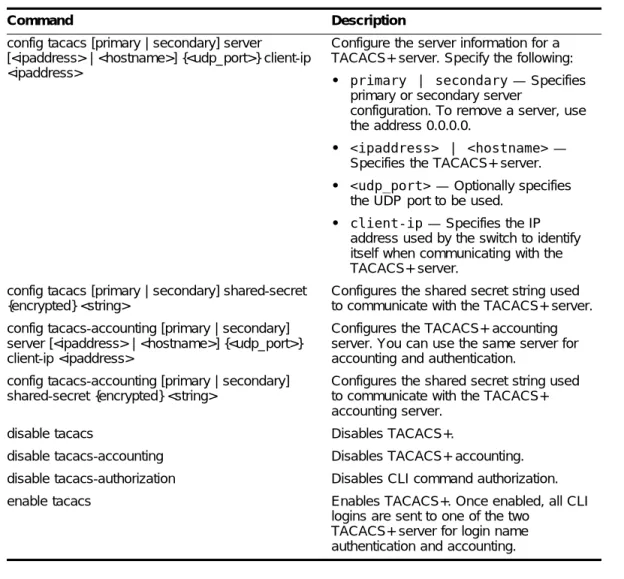
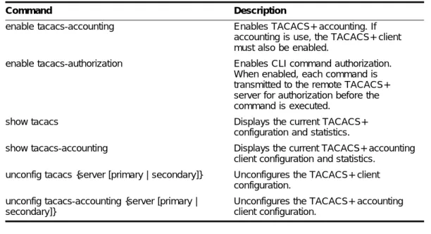
Configuring TACACS+ 65
Using Network Login 66
Using Network Login in Campus Mode 67
Using Network Login in ISP Mode 69
DHCP Server on the Switch 70
Network Login Configuration Commands 70
Displaying Network Login Settings 70
Disabling Network Login 71
Using EAPOL Flooding 71
Using the Simple Network Time Protocol 72
Configuring and Using SNTP 72
SNTP Configuration Commands 75
SNTP Example 75
Chapter 6
Configuring Ports on a Switch
Enabling and Disabling Switch Ports 77
Configuring Switch Port Speed and Duplex Setting 77
Switch Port Commands 79
Load Sharing on the Switch 80
Load-Sharing Algorithms 80
Configuring Switch Load Sharing 81
Contents
Port-Mirroring Commands 83
Port-Mirroring Example 83
Extreme Discovery Protocol 84
EDP Commands 84
Chapter 7
Virtual LANs (VLANs)
Overview of Virtual LANs 85
Benefits 85
Types of VLANs 86
Port-Based VLANs 86
Tagged VLANs 88
VLAN Names 90
Default VLAN 90
Renaming a VLAN 91
Configuring VLANs on the Switch 91
VLAN Configuration Commands 91
VLAN Configuration Examples 92
Displaying VLAN Settings 92
MAC-Based VLANs 93
MAC-Based VLAN Guidelines 93
MAC-Based VLAN Limitations 94
MAC-Based VLAN Example 94
Timed Configuration Download for MAC-Based VLANs 94
Chapter 8
Forwarding Database (FDB)
Overview of the FDB 97
FDB Contents 97
FDB Entry Types 97
How FDB Entries Get Added 98
Associating a QoS Profile with an FDB Entry 98
Configuring FDB Entries 99
FDB Configuration Examples 100
Displaying FDB Entries 100
Chapter 9
Access Policies
Overview of Access Policies 101
Access Control Lists 101
Rate Limits 101
Routing Access Policies 102
Using Access Control Lists 102
Contents
Access Lists 102
Rate Limits 103
How Access Control Lists Work 104
Access Mask Precedence Numbers 104
Specifying a Default Rule 104
The permit-established Keyword 104
Adding Access Mask, Access List, and Rate Limit Entries 105 Deleting Access Mask, Access List, and Rate Limit Entries 106
Verifying Access Control List Configurations 106
Access Control List Commands 106
Access Control List Examples 110
Using Routing Access Policies 114
Creating an Access Profile 114
Configuring an Access Profile Mode 114
Adding an Access Profile Entry 114
Deleting an Access Profile Entry 115
Applying Access Profiles 115
Routing Access Policies for RIP 115
Routing Access Policies for OSPF 117
Making Changes to a Routing Access Policy 118 Removing a Routing Access Policy 118
Routing Access Policy Commands 119
Chapter 10
Network Address Translation (NAT)
Overview 121
Internet IP Addressing 122
Configuring VLANs for NAT 122
NAT Modes 123
Configuring NAT 124
Configuring NAT Rules 124
Creating NAT Rules 125
Creating Static and Dynamic NAT Rules 125
Creating Portmap NAT Rules 125
Creating Auto-Constrain NAT Rules 126
Advanced Rule Matching 126
Configuring Timeouts 127
Displaying NAT Settings 127
Contents
Chapter 11
Ethernet Automatic Protection Switching
Overview of the EAPS Protocol 129
Fault Detection and Recovery 131
Restoration Operations 132
Summit 200 Series Switches in Multi-ring Topologies 133 Commands for Configuring and Monitoring EAPS 134
Creating and Deleting an EAPS Domain 135
Defining the EAPS Mode of the Switch 135
Configuring EAPS Polling Timers 135
Configuring the Primary and Secondary Ports 136
Configuring the EAPS Control VLAN 137
Configuring the EAPS Protected VLANs 137
Enabling and Disabling an EAPS Domain 138
Enabling and Disabling EAPS 138
Unconfiguring an EAPS Ring Port 138
Displaying EAPS Status Information 138
Chapter 12
Quality of Service (QoS)
Overview of Policy-Based Quality of Service 143
Applications and Types of QoS 144
Voice Applications 144
Video Applications 144
Critical Database Applications 144
Web Browsing Applications 145
File Server Applications 145
Configuring QoS for a Port or VLAN 145
Traffic Groupings 146
Access List Based Traffic Groupings 146
MAC-Based Traffic Groupings 147
Explicit Class of Service (802.1p and DiffServ) Traffic Groupings 148
Configuring DiffServ 150
Physical and Logical Groupings 152
Verifying Configuration and Performance 153
QoS Monitor 153
Displaying QoS Profile Information 153
Modifying a QoS Configuration 154
Traffic Rate-Limiting 154
Dynamic Link Context System 154
DLCS Guidelines 155
DLCS Limitations 155
Contents
Chapter 13
Status Monitoring and Statistics
Status Monitoring 157
Port Statistics 159
Port Errors 159
Port Monitoring Display Keys 160
Setting the System Recovery Level 161
Logging 161
Local Logging 162
Remote Logging 163
Logging Configuration Changes 163
Logging Commands 164
RMON 165
About RMON 165
RMON Features of the Switch 165
Configuring RMON 166
Event Actions 167
Chapter 14
Spanning Tree Protocol (STP)
Overview of the Spanning Tree Protocol 169
Spanning Tree Domains 169
Defaults 170
STPD BPDU Tunneling 170
STP Configurations 170
Configuring STP on the Switch 172
STP Configuration Example 175
Displaying STP Settings 175
Disabling and Resetting STP 175
Chapter 15
IP Unicast Routing
Overview of IP Unicast Routing 177
Router Interfaces 178
Populating the Routing Table 179
Subnet-Directed Broadcast Forwarding 180
Proxy ARP 180
ARP-Incapable Devices 181
Proxy ARP Between Subnets 181
Contents
IP Commands 183
Routing Configuration Example 187
Displaying Router Settings 188
Resetting and Disabling Router Settings 189
Configuring DHCP/BOOTP Relay 190
Verifying the DHCP/BOOTP Relay Configuration 190
UDP-Forwarding 190
Configuring UDP-Forwarding 191
UDP-Forwarding Example 191
ICMP Packet Processing 191
UDP-Forwarding Commands 192
Chapter 16
Interior Gateway Routing Protocols
Overview 193
RIP Versus OSPF 194
Overview of RIP 194
Routing Table 195
Split Horizon 195
Poison Reverse 195
Triggered Updates 195
Route Advertisement of VLANs 195
RIP Version 1 Versus RIP Version 2 195
Overview of OSPF 196
Link-State Database 196
Areas 197
Point-to-Point Support 200
Route Re-Distribution 201
Configuring Route Re-Distribution 201
OSPF Timers and Authentication 202
Configuring RIP 203
RIP Configuration Example 205
Displaying RIP Settings 206
Resetting and Disabling RIP 206
Configuring OSPF 206
Configuring OSPF Wait Interval 211
Displaying OSPF Settings 212
OSPF LSD Display 212
Contents
Chapter 17
IP Multicast Groups and IGMP Snooping
Overview 215
Configuring IGMP and IGMP Snooping 216 Displaying IGMP Snooping Configuration Information 217 Clearing, Disabling, and Resetting IGMP Functions 217
Appendix A
Safety Information
Important Safety Information 219
Power 219
Power Cord 220
Connections 220
Lithium Battery 220
Appendix B
Technical Specifications
Summit 200-24 Switch 223
Summit 200-48 Switch 226
Appendix C
Supported Standards
Appendix D
Software Upgrade and Boot Options
Downloading a New Image 231
Rebooting the Switch 232
Saving Configuration Changes 232
Returning to Factory Defaults 233
Using TFTP to Upload the Configuration 233 Using TFTP to Download the Configuration 234
Downloading a Complete Configuration 234
Downloading an Incremental Configuration 234
Scheduled Incremental Configuration Download 234
Remember to Save 235
Upgrading and Accessing BootROM 235
Upgrading BootROM 235
Accessing the BootROM menu 235
Contents
Appendix E
Troubleshooting
LEDs 233
Using the Command-Line Interface 234
Port Configuration 235
VLANs 236
STP 237
Debug Tracing 237
TOP Command 237
Contacting Extreme Technical Support 237
Index
Preface
This preface provides an overview of this guide, describes guide conventions, and lists other publications that may be useful.
Introduction
This guide provides the required information to install the Summit 200 series switch and configure the ExtremeWare™ software running on the Summit 200 series switch.
This guide is intended for use by network administrators who are responsible for installing and setting up network equipment. It assumes a basic working knowledge of:
• Local area networks (LANs)
• Ethernet concepts
• Ethernet switching and bridging concepts
• Routing concepts
• Internet Protocol (IP) concepts
• Simple Network Management Protocol (SNMP)
NOTE
If the information in the release notes shipped with your switch differs from the information in this guide, follow the release notes.
Conventions
Table 1 and Table 2 list conventions that are used throughout this guide.
Related Publications
The publications related to this one are:
• ExtremeWare Release Notes
• Summit 200 Series Switch Release Notes
Documentation for Extreme Networks products is available on the World Wide Web at the following location:
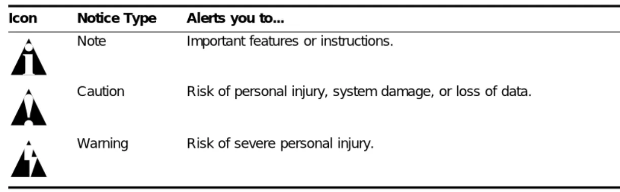
• http://www.extremenetworks.com/ Table 1: Notice Icons
Icon Notice Type Alerts you to...
Note Important features or instructions.
Caution Risk of personal injury, system damage, or loss of data.
Warning Risk of severe personal injury.
Table 2: Text Conventions
Convention Description
Screen displays This typeface indicates command syntax, or represents information as it appears on the screen.
The words “enter” and “type”
When you see the word “enter” in this guide, you must type something, and then press the Return or Enter key. Do not press the Return or Enter key when an instruction simply says “type.”
[Key] names Key names are written with brackets, such as [Return] or [Esc]. If you must press two or more keys simultaneously, the key names are linked with a plus sign (+). Example:
Press [Ctrl]+[Alt]+[Del].
Words in italicized type Italics emphasize a point or denote new terms at the place where they are defined in the text.
1
Summit 200 Series Switch Overview
This chapter describes the features and functionality of the Summit 200 series switches:
• Summit 200 Series Switches on page 15
• Summary of Features on page 15
• Summit 200-24 Switch Physical Features on page 16
• Summit 200-48 Switch Physical Features on page 19
• Mini-GBIC Type and Hardware/Software Support on page 22
Summit 200 Series Switches
The Summit 200 series switches include the following switch models:
• Summit 200-24 switch
• Summit 200-48 switch
Summary of Features
The Summit 200 series switches support the following ExtremeWare features:
• Virtual local area networks (VLANs) including support for IEEE 802.1Q and IEEE 802.1p
• Spanning Tree Protocol (STP) (IEEE 802.1D)
• Quality of Service (QoS) including support for IEEE 802.1p, MAC QoS, and four hardware queues
• Wire-speed Internet Protocol (IP) routing
• DHCP/BOOTP Relay
• Network Address Translation (NAT)
• Extreme Standby Router Protocol (ESRP) - Aware support
• Ethernet Automated Protection Switching (EAPS) support
Summit 200 Series Switch Overview
• Access-policy support for routing protocols
• Access list support for packet filtering
• Access list support for rate-limiting
• IGMP snooping to control IP multicast traffic
• Load sharing on multiple ports
• RADIUS client and per-command authentication support
• TACACS+ support
• Network Login
• Console command-line interface (CLI) connection
• Telnet CLI connection
• SSH2 connection
• Simple Network Management Protocol (SNMP) support
• Remote Monitoring (RMON)
• Traffic mirroring for ports
Summit 200-24 Switch Physical Features
The Summit 200-24 switch is a compact enclosure (see Figure 1) one rack unit in height (1.75 inches or 44.45 mm) that provides 24 autosensing 10BASE-T/100BASE-TX ports using RJ-45 connectors. It also provides two 10/100/1000BASE-T Gigabit Ethernet uplink ports using RJ-45 connectors and two optical ports that also allow Gigabit Ethernet uplink connections through Extreme 1000BASE-SX, 1000BASE-LX, or 1000BASE-ZX Small Form Factor pluggable (SFP) Gigabit Interface Connectors (GBICs)—also known as mini-GBICs—using LC optical fiber connectors.
Summit 200-24 Switch Front View
Figure 1 shows the Summit 200-24 switch front view.
Figure 1: Summit 200-24 switch front view
NOTE
See Table 5 for information about supported mini-GBIC types and distances.
LC24001A
10/100 Mbps ports Console
port Mini-GBIC
port status LEDs
Unit stacking ID LED
Mini-GBIC ports 1000-baseT ports
Summit 200-24 Switch Physical Features
NOTE
See “Summit 200-24 Switch LEDs” on page 17 for more details.
Console Port
Use the console port (9-pin, “D” type connector) for connecting a terminal and carrying out local management.
Port Connections
The Summit 200-24 switch has 24 10BASE-T/100BASE-TX ports using RJ-45 connectors for communicating with end stations and other devices over 10/100Mbps Ethernet.
The switch also has four Gigabit Ethernet uplink ports. These ports are labeled 25 and 26 on the front panel of the switch. Two of the ports are 10/100/1000BASE-T ports using RJ-45 connectors. The other two ports are unpopulated receptacles for mini-SFP GBICs, using optical fibers with LC connectors. The Summit 200-24 switch supports the use of 1000BASE-SX, 1000BASE-LX, or 1000BASE-ZX mini-GBICs.
NOTE
Only mini-GBICs that have been certified by Extreme Networks (available from Extreme Networks) should be inserted into the mini-GBIC receptacles on the Summit 200 series switch.
Only two of the four Gigabit Ethernet uplink ports can be active at one time. For example, you can use both 1000BASE-T ports, both mini-GBIC ports, or a combination of one 1000BASE-T port and one mini-GBIC.
NOTE
For information on the mini-GBIC, see “Mini-GBIC Type and Hardware/Software Support” on page 22.
Full-Duplex
The Summit 200-24 switch provides full-duplex support for all ports. Full-duplex allows frames to be transmitted and received simultaneously and, in effect, doubles the bandwidth available on a link. All 10/100 Mbps ports on the Summit 200-24 switch autonegotiate for half- or full-duplex operation.
Summit 200-24 Switch LEDs
Summit 200 Series Switch Overview
Summit 200-24 Switch Rear View
Figure 2 shows the rear view of the Summit 200-24 switch.
Figure 2: Summit 200-24 switch rear view Table 3: Summit 200-24 switch LED behavior
Unit Status LED (MGMT LED)
Color Indicates
Green solid Green blinking Amber
The Summit switch is operating normally. The Summit switch POST is in progress.
The Summit switch has failed its POST or an overheat condition is detected.
Fan LED
Color Indicates
Green
Amber blinking
The fan is operating normally.
A failed condition is present on the fan.
Port Status LEDs (Ports 1–26) Color Indicates
Green
Green blinking Off
Link is present; port is enabled.
Link is present, port is enabled, and there is activity on the port. Link is not present or the port is disabled.
Media-Selection (Fiber) LEDs (Ports 25 and 26) Color Indicates
Green Off
Fiber link is selected; mini-GBIC is present and being used for the Gigabit Ethernet uplink.
1000BASE-T link is selected; the switch is using the RJ-45 port for the Gigabit Ethernet uplink.
Unit Stacking ID Number LED Color Indicates
N/A When several Summit 200-24 switches are interconnected (stacked), each switch will be assigned a unique stacking ID number that will be visible in the unit stacking ID number LED. The switch acting as the stack master will be assigned the number 0, which is the default.
LC24002
Summit 200-48 Switch Physical Features
Power Socket
The Summit 200-24 switch automatically adjusts to the supply voltage. The power supply operates down to 90 V.
Serial Number
Use this serial number for fault-reporting purposes.
MAC Address
This label shows the unique Ethernet MAC address assigned to this device.
NOTE
The Summit 200-24 switch certification and safety label is located on the bottom of the switch.
Summit 200-48 Switch Physical Features
The Summit 200-48 switch is a compact enclosure (see Figure 3) one rack unit in height (1.75 inches or 44.45 mm) that provides 48 autosensing 10BASE-T/100BASE-TX ports using RJ-45 connectors. It also provides two 10/100/1000BASE-T Gigabit Ethernet uplink ports using RJ-45 connectors and two optical ports that also allow Gigabit Ethernet uplink connections through Extreme 1000BASE-SX, 1000BASE-LX, or 1000BASE-ZX SFP mini-GBICs using optical fibers with LC connectors.
Summit 200-48 Switch Front View
Figure 3 shows the Summit 200-48 switch front view.
Figure 3: Summit 200-48 switch front view
NOTE
See Table 5 for information about supported mini-GBIC types and distances.
NOTE
LC48001
10/100 Mbps ports
Console port
1000-baseT ports Mini-GBIC ports
Summit 200 Series Switch Overview
Console Port
Use the console port (9-pin, “D” type connector) for connecting a terminal and carrying out local management.
Port Connections
The Summit 200-48 switch has 48 10BASE-T/100BASE-TX ports using RJ-45 connectors for communicating with end stations and other devices over 10/100Mbps Ethernet.
The switch also has four Gigabit Ethernet uplink ports. These ports are labeled 49 and 50 on the front panel of the switch. Two of the ports are 10/100/1000BASE-T ports using RJ-45 connectors. The other two ports are unpopulated receptacles for mini-SFP GBICs, using optical fibers with LC connectors. The Summit 200-48 switch supports the use of 1000BASE-SX, 1000BASE-LX, or 1000BASE-ZX mini-GBICs.
NOTE
Only mini-GBICs that have been certified by Extreme Networks (available from Extreme Networks) should be inserted into the mini-GBIC receptacles on the Summit 200 series switch.
Only two of the four Gigabit Ethernet uplink ports can be active at one time. For example, you can use both 1000BASE-T ports, both mini-GBIC ports, or a combination of one 1000BASE-T port and one mini-GBIC.
NOTE
For information on the mini-GBIC, see “Mini-GBIC Type and Hardware/Software Support” on page 22.
NOTE
When configuring the Summit 200-48 switch, all ports specified as mirrored ports and mirroring port, or ACL ingress ports and egress port, must belong to the same port group. Port group 1 consists of ports 1 through 24 and port 49; port group 2 consists of ports 25 through 48 and port 50.
Full-Duplex
The Summit 200-48 switch provides full-duplex support for all ports. Full-duplex allows frames to be transmitted and received simultaneously and, in effect, doubles the bandwidth available on a link. All 10/100 Mbps ports on the Summit 200-48 switch autonegotiate for half- or full-duplex operation.
Summit 200-48 Switch Physical Features
Summit 200-48 Switch LEDs
Table 4 describes the LED behavior on the Summit 200-48 switch.
Summit 200-48 Switch Rear View
Figure 4 shows the rear view of the Summit 200-48 switch.
Figure 4: Summit 200-48 switch rear view
Power Socket
The Summit 200-48 switch automatically adjusts to the supply voltage. The power supply operates down to 90 V.
Table 4: Summit 200-48 switch LED behavior
Unit Status LED (MGMT LED)
Color Indicates
Green solid Green blinking Amber
The Summit switch is operating normally. The Summit switch POST is in progress.
The Summit switch has failed its POST or an overheat condition is detected.
Fan LED
Color Indicates
Green
Amber blinking
The fan is operating normally.
A failed condition is present on the fan.
Port Status LEDs (Ports 1–50) Color Indicates
Green
Green blinking Off
Link is present; port is enabled.
Link is present, port is enabled, and there is activity on the port. Link is not present or the port is disabled.
Media-Selection (Fiber) LEDs (Ports 49 and 50) Color Indicates
Green Off
Fiber link is selected; mini-GBIC is present and being used for the Gigabit Ethernet uplink.
1000BASE-T link is selected; the switch is using the RJ-45 port for the Gigabit Ethernet uplink.
LC48002
Summit 200 Series Switch Overview
Serial Number
Use this serial number for fault-reporting purposes.
MAC Address
This label shows the unique Ethernet MAC address assigned to this device.
NOTE
The Summit 200-48 switch certification and safety label is located on the bottom of the switch.
Mini-GBIC Type and Hardware/Software Support
The Summit 200 series switch supports the SFP GBIC, also known as the mini-GBIC, in three types: the SX mini-GBIC, which conforms to the 1000BASE-SX standard, the LX mini-GBIC, which conforms to the 1000BASE-LX standard, and the ZX mini-GBIC, a long-haul mini-GBIC that conforms to the IEEE 802.3z standard. The system uses identifier bits to determine the media type of the mini-GBIC that is installed. The Summit 200 series switches support only the SFP mini-GBIC.
NOTE
Only mini-GBICs that have been certified by Extreme Networks (available from Extreme Networks) should be inserted into the mini-GBIC receptacles on the Summit 200 series switch.
This section describes the mini-GBIC types and specifications.
Mini-GBIC Type and Specifications
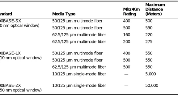
Table 5 describes the mini-GBIC type and distances for the Summit 200 series switches.
Table 5: Mini-GBIC types and distances
Standard Media Type
Mhz•Km Rating Maximum Distance (Meters) 1000BASE-SX
(850 nm optical window)
50/125 µm multimode fiber 50/125 µm multimode fiber 62.5/125 µm multimode fiber 62.5/125 µm multimode fiber
400 500 160 200 500 550 220 275 1000BASE-LX
(1310 nm optical window)
50/125 µm multimode fiber 50/125 µm multimode fiber 62.5/125 µm multimode fiber 10/125 µm single-mode fiber
400 500 500 — 550 550 550 5,000 1000BASE-ZX
(1550 nm optical window)
Mini-GBIC Type and Hardware/Software Support
SX Mini-GBIC Specifications
Table 6 describes the specifications for the SX mini-GBIC.
Total optical system budget for the SX mini-GBIC is 11.5 dB. Extreme Networks recommends that 3 dB of the total budget be reserved for losses induced by cable splices, connectors, and operating margin. While 8.5 dB remains available for cable-induced attenuation, the 1000BASE-SX standard specifies supported distances of 275 meters over 62.5 micron multimode fiber and 550 meters over 50 micron multimode fiber. There is no minimum attenuation or minimum cable length restriction.
LX Mini-GBIC Specifications
Table 7 describes the specifications for the LX mini-GBIC.
Total optical system budget for the LX mini-GBIC is 13.5 dB. Measure cable plant losses with a 1310 nm light source and verify this to be within budget. When calculating the maximum distance attainable using optical cable with a specified loss per kilometer (for example 0.25 dB/km) Extreme Networks recommends that 3 dB of the total budget be reserved for losses induced by cable splices, connectors, and operating margin. Thus, 10.5 dB remains available for cable induced attenuation. There is no Table 6: SX mini-GBIC specifications
Parameter Minimum Typical Maximum Transceiver
Optical output power –9.5 dBm –4 dBm
Center wavelength 830 nm 850 nm 860 nm
Receiver
Optical input power sensitivity –21 dBm
Optical input power maximum –4 dBm
Operating wavelength 830 nm 860 nm
General
Total system budget 11.5 dB
Table 7: LX mini-GBIC specifications
Parameter Minimum Typical Maximum Transceiver
Optical output power –9.5 dBm –3 dBm
Center wavelength 1275 nm 1310 nm 1355 nm
Receiver
Optical input power sensitivity –23 dBm
Optical input power maximum –3 dBm
Operating wavelength 1270 nm 1355 nm
General
Summit 200 Series Switch Overview
ZX Mini-GBIC Specifications
Table 8 describes the specifications for the ZX mini-GBIC.
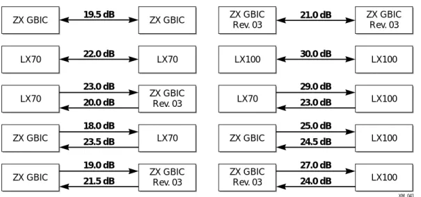
Long Range GBIC System Budgets
Measure cable plant losses with a 1550 nm light source and verify this to be within budget. When calculating the maximum distance attainable using optical cable with a specified loss per kilometer (for example 0.25 dB/km), Extreme Networks recommends that 3 dB of the total budget be reserved for losses induced by cable splices, connectors, and operating margin. Figure 5 shows the total optical system budget between long range GBICs in various end-to-end combinations (ZX, ZX Rev 03, LX70, and LX100).
NOTE
The ZX mini-GBIC is equivalent to the ZX Rev 03 GBIC.
Figure 5: Total optical system budgets for long range GBICs Table 8: ZX mini-GBIC specifications
Parameter Minimum Typical Maximum Transceiver
Optical output power –2 dBm 0 dBm 3 dBm
Center wavelength 1540 nm 1550 nm 1570 nm
Receiver
Optical input power sensitivity –23 dBm
Optical input power maximum –3 dBm
Operating wavelength 1540 nm 1550 nm 1570 nm
XM_041
ZX GBIC ZX GBIC
Rev. 03 ZX GBIC Rev. 03 ZX GBIC Rev. 03 21.0 dB 19.5 dB
ZX GBIC ZX GBIC
LX70 LX70
18.0 dB 23.5 dB
ZX GBIC LX70
29.0 dB 23.0 dB
19.0 dB 21.5 dB 23.0 dB
20.0 dB LX70 LX100
LX100 LX100 30.0 dB ZX GBIC ZX GBIC Rev. 03 LX100 LX100 25.0 dB 24.5 dB 27.0 dB 24.0 dB
LX70 ZX GBIC
Rev. 03
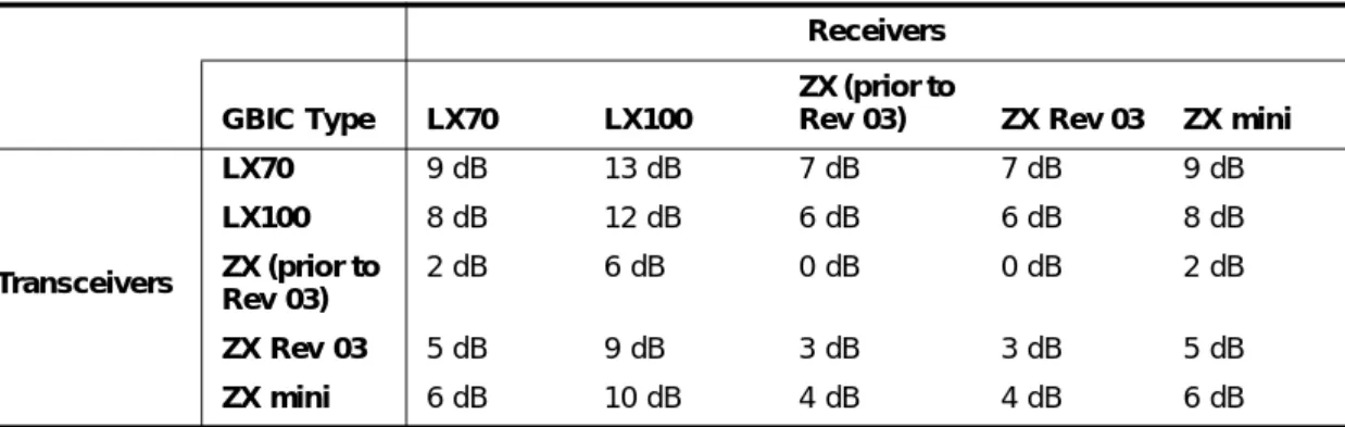
Mini-GBIC Type and Hardware/Software Support
Table 9 lists the minimum attenuation requirements to prevent saturation of the receiver for each type of long range GBIC.
Table 9: Minimum attenuation requirements
Receivers GBIC Type LX70 LX100
ZX (prior to
Rev 03) ZX Rev 03 ZX mini
Transceivers
LX70 9 dB 13 dB 7 dB 7 dB 9 dB
LX100 8 dB 12 dB 6 dB 6 dB 8 dB
ZX (prior to Rev 03)
2 dB 6 dB 0 dB 0 dB 2 dB
ZX Rev 03 5 dB 9 dB 3 dB 3 dB 5 dB
2
Switch Installation
This chapter describes the following topics:
• Determining the Switch Location on page 27
• Following Safety Information on page 28
• Installing the Switch on page 28
• Connecting Equipment to the Console Port on page 29
• Powering On the Switch on page 30
• Checking the Installation on page 31
• Logging In for the First Time on page 31
• Installing or Replacing a Mini-Gigabit Interface Connector (Mini-GBIC) on page 32
CAUTION
Use of controls or adjustments of performance or procedures other than those specified herein can result in hazardous radiation exposure.
Determining the Switch Location
The Summit 200 series switch is suited for use in the office, where it can be free-standing or mounted in a standard 19-inch equipment rack. Alternately, the device can be rack-mounted in a wiring closet or equipment room. Two mounting brackets are supplied with the switch.
When deciding where to install the switch, ensure that:
• The switch is accessible and cables can be connected easily.
• Water or moisture cannot enter the case of the unit.
• Air-flow around the unit and through the vents in the side of the case is not restricted. You should provide a minimum of 1 inch (25 mm) clearance.
• No objects are placed on top of the unit.
Switch Installation
Following Safety Information
Before installing or removing any components of the switch, or before carrying out any maintenance procedures, read the safety information provided in w of this guide.
Installing the Switch
The Summit 200 series switch switch can be mounted in a rack, or placed free-standing on a tabletop.
Rack Mounting
CAUTION
Do not use the rack mount kits to suspend the switch from under a table or desk, or to attach the switch to a wall.
To rack mount the Summit 200 series switch:
1 Place the switch upright on a hard flat surface, with the front facing you.
2 Remove the existing screws from the sides of the case (retain the screws for Step 4).
3 Locate a mounting bracket over the mounting holes on one side of the unit.
4 Insert the screws and fully tighten with a suitable screwdriver, as shown in Figure 6.
Figure 6: Fitting the mounting bracket
5 Repeat steps 2 through 4 for the other side of the switch.
6 Insert the switch into the 19-inch rack.
7 Secure the switch with suitable screws (not provided).
8 Connect the switch to the redundant power supply (if applicable).
9 Connect cables.
Connecting Equipment to the Console Port
Free-Standing
The Summit 200 series switch is supplied with four self-adhesive rubber pads. Apply the pads to the underside of the device by sticking a pad in the marked area at each corner of the switch.
Stacking the Switch and Other Devices
You can place up to four Summit switches on top of one another.
NOTE
This relates only to stacking the devices directly one on top of one another.
Apply the pads to the underside of the device by sticking a pad at each corner of the switch. Place the devices on top of one another, ensuring that the corners align.
Connecting Equipment to the Console Port
Connection to the console port is used for direct local management. The switch console port settings are set as follows:
• Baud rate—9600
• Data bits—8
• Stop bit—1
• Parity—None
• Flow control—None
NOTE
If you set the switch console port flow control to XON/XOFF rather than None, you will be unable to access the switch. Do not set the switch console port flow control to XON/XOFF.
The terminal connected to the console port on the switch must be configured with the same settings. This procedure is described in the documentation supplied with the terminal.
Appropriate cables are available from your local supplier. To make your own cables, pinouts for a DB-9 male console connector are described in Table 10.
Table 10: Console Connector Pinouts
Function Pin Number Direction
DCD (data carrier detect) 1 In
RXD (receive data) 2 In
TXD (transmit data) 3 Out
Switch Installation
Figure 7 shows the pin-outs for a 9-pin to RS-232 25-pin null-modem cable.
Figure 7: Null-modem cable pin-outs
Figure 8 shows the pin-outs for a 9-pin to 9-pin PC-AT null-modem serial cable.
Figure 8: PC-AT serial null-modem cable pin-outs
Powering On the Switch
To turn on power to the switch, connect the AC power cable to the switch and then to the wall outlet. Turn the on/off switch to the on position.
RTS (request to send) 7 Out
CTS (clear to send 8 In
Table 10: Console Connector Pinouts (continued)
Function Pin Number Direction
Screen TxD RxD Ground RTS CTS DSR DCD DTR
Cable connector: 9-pin female
Summit
Cable connector: 25-pin male/female
PC/Terminal Screen RxD TxD Ground RTS DTR CTS DSR DCD Shell 3 2 5 7 8 6 1 4 1 3 2 7 4 20 5 6 8 ser_sum1 Screen DTR TxD RxD CTS Ground DSR RTS DCD
Cable connector: 9-pin female
Summit
Cable connector: 9-pin female
PC-AT Serial Port
Screen DCD RxD TxD DTR Ground DSR RTS CTS Shell 4 3 2 8 5 6 7 1 Shell 1 2 3 4 5 6 7 8 ser_sum2
Checking the Installation
Checking the Installation
After turning on power to the Summit 200 series switch, the device performs a Power On Self-Test (POST).
During the POST, all ports are temporarily disabled, the port LED is off, and the MGMT LED flashes. The MGMT LED flashes until the switch successfully passes the POST.
If the switch passes the POST, the MGMT LED is solid green. If the switch fails the POST, the MGMT LED is amber.
NOTE
For more information on the LEDs, see Chapter 1, “Summit 200 Series Switch Overview”.
Logging In for the First Time
After the Summit 200 series switch completes the POST, it is operational. Once operational, you can log in to the switch and configure an IP address for the default VLAN (named default).
To configure the IP settings manually, follow these steps:
1 Connect a terminal or workstation running terminal-emulation software to the console port.
2 At your terminal, press [Return] one or more times until you see the login prompt.
3 At the login prompt, enter the default user name admin to log on with administrator privileges. For example:
login: admin
Administrator capabilities allow you to access all switch functions.
NOTE
For more information on switch security, see Chapter 4, “Accessing the Switch”. 4 At the password prompt, press [Return].
The default name, admin, has no password assigned. When you have successfully logged on to the switch, the command-line prompt displays the name of the switch (for example, Summit200-24) in its prompt.
5 Assign an IP address and subnetwork mask for VLAN default by typing config vlan default ipaddress 123.45.67.8 255.255.255.0 Your changes take effect immediately.
6 Save your configuration changes so that they will be in effect after the next switch reboot, by typing save
Switch Installation
7 When you are finished using the facility, logout of the switch by typing logout
NOTE
After two incorrect login attempts, the Summit 200 series switch locks you out of the login facility. You must wait a few minutes before attempting to log in again.
Installing or Replacing a Mini-Gigabit Interface Connector
(Mini-GBIC)
This section describes the safety precautions and preparation steps that you must perform before inserting and securing a mini-GBIC.
Safety Information
Before you install or replace a mini-GBIC, read the safety information in this section.
WARNING!
Mini-GBICs can emit invisible laser radiation. Avoid direct eye exposure to beam.
Mini-GBICs are a class 1 laser device. Use only devices approved by Extreme Networks.
NOTE
Remove the LC fiber-optic connector from the mini-GBIC prior to removing the mini-GBIC from the switch.
Preparing to Install or Replace a Mini-GBIC
To ensure proper installation, complete the following tasks before inserting the mini-GBIC:
• Disable the port that is needed to install or replace the mini-GBIC.
• Inspect and clean the fiber tips, coupler, and connectors.
• Prepare and clean an external attenuator, if needed.
• Do not stretch the fiber.
• Make sure the bend radius of the fiber is not less than 2 inches.
In addition to the previously described tasks, Extreme Networks recommends the following when installing or replacing mini-GBICs on an active network:
• Use the same type of mini-GBIC at each end of the link.
• Connect one end of the link to the Tx port. Without an attenuator, measure the total loss from the Tx port to the other side of the link.
Installing or Replacing a Mini-Gigabit Interface Connector (Mini-GBIC)
Removing and Inserting a Mini-GBIC
You can remove mini-GBICs from, or insert mini-GBICs into your Summit 200 series switch without powering off the system. Figure 9 shows the two types of mini-GBIC modules.
Figure 9: Mini-GBIC modules
Mini-GBICs are a 3.3 V Class 1 laser device. Use only devices approved by Extreme Networks.
WARNING!
Mini-GBICs can emit invisible laser radiation. Avoid direct eye exposure to beam.
NOTE
Remove the LC fiber-optic connector from the mini-GBIC prior to removing the mini-GBIC from the switch.
NOTE
If you see an amber blinking Mini-GBIC port status LED on your Summit 200 series switch, the mini-GBIC installed in your switch is one that is not approved or supported by Extreme Networks. To correct this problem, ensure that you install a mini-GBIC that is approved and supported by Extreme Networks.
Removing a Mini-GBIC
To remove a mini-GBIC similar to the one labeled “Module A” in Figure 9, gently press and hold the black plastic tab at the bottom of the connector to release the mini-GBIC, and pull the mini-GBIC out of the SFP receptacle on the switch.
To remove a mini-GBIC similar to the one labeled “Module B” in Figure 9, rotate the front handle down and pull the mini-GBIC out of the slot.
XM_024
Switch Installation
Inserting a Mini-GBIC
NOTEMini-GBICs can be installed in the SFP mini-GBIC receptacles for ports 25 and 26 on the Summit 200 series switches.
To insert a mini-GBIC connector:
1 Holding the mini-GBIC by its sides, insert the mini-GBIC into the SFP receptacle on the switch.
2 Push the mini-GBIC into the SFP receptacle until you hear an audible click, indicating the mini-GBIC is securely seated in the SFP receptacle. If the mini-GBIC has a handle, push up on the handle to secure the mini-GBIC.
3
ExtremeWare Overview
This chapter describes the following topics:
• Summary of Features on page 35
• Software Licensing on page 38
• Security Licensing for Features Under License Control on page 39
• Software Factory Defaults on page 40
ExtremeWare is the full-featured software operating system that is designed to run on the Summit 200 series switch. This section describes the supported ExtremeWare features for the Summit 200 series switch.
Summary of Features
The Summit 200 series switch supports the following ExtremeWare features:
• Virtual local area networks (VLANs) including support for IEEE 802.1Q and IEEE 802.1p
• Spanning Tree Protocol (STP) (IEEE 802.1D)
• Quality of Service (QoS) including support for IEEE 802.1p, MAC QoS, and four hardware queues
• Wire-speed Internet Protocol (IP) routing
• DHCP/BOOTP Relay
• Network Address Translation (NAT)
• Extreme Standby Router Protocol (ESRP) - Aware support
• Ethernet Automated Protection Switching (EAPS) support
• Routing Information Protocol (RIP) version 1 and RIP version 2
• Open Shortest Path First (OSPF) routing protocol
• Diffserv support
• Access-policy support for routing protocols
ExtremeWare Overview
• RADIUS client and per-command authentication support
• TACACS+ support
• Network Login
• Console command-line interface (CLI) connection
• Telnet CLI connection
• SSH2 connection
• Simple Network Management Protocol (SNMP) support
• Remote Monitoring (RMON)
• Traffic mirroring for ports
Virtual LANs (VLANs)
ExtremeWare has a VLAN feature that enables you to construct your broadcast domains without being restricted by physical connections. A VLAN is a group of location- and topology-independent devices that communicate as if they were on the same physical local area network (LAN).
Implementing VLANs on your network has the following three advantages:
• They help to control broadcast traffic. If a device in VLAN Marketing transmits a broadcast frame, only VLAN Marketing devices receive the frame.
• They provide extra security. Devices in VLAN Marketing can only communicate with devices on VLAN Sales using routing services.
• They ease the change and movement of devices on networks.
NOTE
For more information on VLANs, see Chapter 7, “Virtual LANs (VLANs)”.
Spanning Tree Protocol
The Summit 200 series switch supports the IEEE 802.1D Spanning Tree Protocol (STP), which is a bridge-based mechanism for providing fault tolerance on networks. STP enables you to implement parallel paths for network traffic, and ensure that:
• Redundant paths are disabled when the main paths are operational.
• Redundant paths are enabled if the main traffic paths fail.
A single spanning tree can span multiple VLANs.
NOTE
Summary of Features
Quality of Service
ExtremeWare has Quality of Service (QoS) features that support IEEE 802.1p, MAC QoS, and four queues. These features enable you to specify service levels for different traffic groups. By default, all traffic is assigned the “normal” QoS policy profile. If needed, you can create other QoS policies and rate-limiting access control lists and apply them to different traffic types so that they have different maximum bandwidth, and priority.
NOTE
For more information on Quality of Service, see Chapter 12, “Quality of Service (QoS)”.
Unicast Routing
The Summit 200 series switch can route IP traffic between the VLANs that are configured as virtual router interfaces. Static IP routes are maintained in the routing table. The following routing protocols are supported:
• RIP version 1
• RIP version 2
• OSPF
NOTE
For more information on IP unicast routing, see Chapter 15, “IP Unicast Routing”.
Load Sharing
Load sharing allows you to increase bandwidth and resiliency by using a group of ports to carry traffic in parallel between systems. The sharing algorithm allows the switch to use multiple ports as a single logical port. For example, VLANs see the load-sharing group as a single virtual port. The algorithm also guarantees packet sequencing between clients.
NOTE
For information on load sharing, see Chapter 6, “Configuring Ports on a Switch”.
ESRP-Aware Switches
Extreme switches that are not running ESRP, but are connected on a network that has other Extreme switches running ESRP are ESRP-aware. When ESRP-aware switches are attached to ESRP-enabled switches, the ESRP-aware switches reliably perform fail-over and fail-back scenarios in the prescribed recovery times. No configuration of this feature is necessary.
ExtremeWare Overview
and the FDB timer used by the other vendor’s layer 2 switch. As such, ESRP can be used with layer 2 switches from other vendors, but the recovery times vary.
The VLANs associated with the ports connecting an ESRP-aware switch to an ESRP-enabled switch must be configured using an 802.1Q tag on the connecting port, or, if only a single VLAN is involved, as untagged using the protocol filter any. ESRP will not function correctly if the ESRP-aware switch interconnection port is configured for a protocol-sensitive VLAN using untagged traffic.
Software Licensing
Some Extreme Networks products have capabilities that are enabled by using a license key. Keys are typically unique to the switch, and are not transferable. Keys are stored in NVRAM and, once entered, persist through reboots, software upgrades, and reconfigurations. The following sections describe the features that are associated with license keys.
Feature Licensing
Summit 200 series switches support software licensing for different levels of functionality. In
ExtremeWare version 6.2e.2, feature support is separated into two sets: Edge and Advanced Edge. Edge is a subset of Advanced Edge.
Edge Functionality
Edge functionality requires no license key. Summit 200 series switches have Edge functionality without the requirement of a license key. Edge functionality includes all switching functions, and also includes all available layer 3 QoS, access list, and ESRP-aware functions. Layer 3 routing functions include support for:
• IP routing using RIP version 1 and/or RIP version 2
• IP routing between directly attached VLANs
• IP routing using static routes
Advanced Edge Functionality
The Advanced Edge license enables support of additional functions, including:
• Rate-limiting ACLs
• IP routing using OSPF
• EAPS Edge (cannot be a core node on the ring)
• Network Login
• RADIUS and TACACS+ command authentication
• Network Address Translation (NAT)
Enabling the Advanced Edge Functionality
To enable the Advanced Edge software feature license, use the following command: enable license advanced-edge <license_key>
Security Licensing for Features Under License Control
NOTE
The command unconfig switch all does not clear licensing information. Once it is enabled on the switch, this license cannot be disabled.
Verifying the Advanced Edge License
To verify the Advanced Edge license, use the show switch command.
Obtaining an Advanced Edge License
You can order the desired functionality from the factory, using the appropriate model of the desired product. If you order licensing from the factory, the switch arrives packaged with a certificate that contains the unique license key(s), and instructions for enabling the correct functionality on the switch. The certificate is typically packaged with the switch documentation. Once the license key is entered, it should not be necessary to enter the information again. However, we recommend keeping the certificate for your records.
You can upgrade the Advanced Edge licensing of an existing product by purchasing a voucher for the desired product and functionality. Please contact your supplier to purchase a voucher.
The voucher contains information and instructions on obtaining a license key for the switch using the Extreme Networks Support website at:
http://esupport.extremenetworks.com
or by phoning Extreme Networks Technical Support at:
• (800) 998-2408
• (408) 579-2826
Security Licensing for Features Under License Control
Certain additional ExtremeWare security features, such as the use of Secure Shell (SSH2) encryption, might be under United States export restriction control. Extreme Networks ships these security features in a disabled state. In order to enable the use of these features, you must first obtain an export license, which you can do through Extreme Networks (at no extra charge).
SSH2 Encryption
ExtremeWare version 6.0 and above supports the SSH2 protocol. SSH2 allows the encryption of Telnet session data. The encryption methods used are under U.S. export restriction control.
To obtain information on enabling SSH2 encryption, access the Extreme Networks Support website at:
http://esupport.extremenetworks.com
ExtremeWare Overview
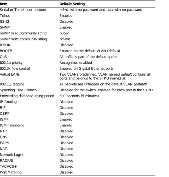
Software Factory Defaults
Table 11 shows factory defaults for ExtremeWare features supported on the Summit 200 series switch.
NOTE
For default settings of individual ExtremeWare features, see the applicable individual chapters in this guide.
Table 11: ExtremeWare Software Feature Factory Defaults for the Summit 200 Series
Item Default Setting
Serial or Telnet user account admin with no password and user with no password
Telnet Enabled
SSH2 Disabled
SNMP Enabled
SNMP read community string public
SNMP write community string private
RMON Disabled
BOOTP Enabled on the default VLAN (default)
QoS All traffic is part of the default queue 802.1p priority Recognition enabled
802.3x flow control Enabled on Gigabit Ethernet ports
Virtual LANs Two VLANs predefined. VLAN named default contains all ports and belongs to the STPD named s0
802.1Q tagging All packets are untagged on the default VLAN (default) Spanning Tree Protocol Disabled for the switch; enabled for each port in the STPD Forwarding database aging period 300 seconds (5 minutes)
IP Routing Disabled
RIP Disabled
OSPF Disabled
IGMP Enabled
IGMP snooping Enabled
NTP Disabled
DNS Disabled
EAPS Disabled
NAT Disabled
Network Login Disabled
RADIUS Disabled
TACACS+ Disabled
4
Accessing the Switch
This chapter describes the following topics:
• Understanding the Command Syntax on page 41
• Line-Editing Keys on page 43
• Command History on page 44
• Common Commands on page 44
• Configuring Management Access on page 46
• Domain Name Service Client Services on page 49
• Checking Basic Connectivity on page 50
Understanding the Command Syntax
This section describes the steps to take when entering a command. Refer to the sections that follow for detailed information on using the command-line interface.
When entering a command at the prompt, ensure that you have the appropriate privilege level. Most configuration commands require you to have the administrator privilege level. To use the command-line interface (CLI), follow these steps:
1 Enter the command name.
If the command does not include a parameter or values, skip to step 3. If the command requires more information, continue to step 2.
2 If the command includes a parameter, enter the parameter name and values.
3 The value part of the command specifies how you want the parameter to be set. Values include numerics, strings, or addresses, depending on the parameter.
4 After entering the complete command, press [Return].
NOTE
If an asterisk (*) appears in front of the command-line prompt, it indicates that you have outstanding configuration changes that have not been saved. For more information on saving configuration changes,
Accessing the Switch
Syntax Helper
The CLI has a built-in syntax helper. If you are unsure of the complete syntax for a particular command, enter as much of the command as possible and press [Return]. The syntax helper provides a list of options for the remainder of the command.
The syntax helper also provides assistance if you have entered an incorrect command.
Command Completion with Syntax Helper
ExtremeWare provides command completion by way of the [Tab] key. If you enter a partial command, pressing the [Tab] key posts a list of available options, and places the cursor at the end of the command.
Abbreviated Syntax
Abbreviated syntax is the most unambiguous, shortest allowable abbreviation of a command or parameter. Typically, this is the first three letters of the command.
In command tables throughout this guide, abbreviated syntax is noted using bold characters.
NOTE
When using abbreviated syntax, you must enter enough characters to make the command unambiguous and distinguishable to the switch.
Command Shortcuts
All named components of the switch configuration must have a unique name. Components are named using the create command. When you enter a command to configure a named component, you do not need to use the keyword of the component. For example, to create a VLAN, you must enter a unique VLAN name:
create vlan engineering
Once you have created the VLAN with a unique name, you can then eliminate the keyword vlan from all other commands that require the name to be entered. For example, on the stand-alone switch, instead of entering the command
config vlan engineering delete port 1-3,6 you could enter the following shortcut:
config engineering delete port 1-3,6
Summit 200 Series Switch Numerical Ranges
Commands that require you to enter one or more port numbers on a Summit 200 series switch use the parameter <portlist> in the syntax. A portlist can be a range of numbers, for example:
port 1-3
You can add additional port numbers to the list, separated by a comma: port 1-3,6,8
Line-Editing Keys
Names
All named components of the switch configuration must have a unique name. Names must begin with an alphabetical character and are delimited by whitespace, unless enclosed in quotation marks.
Symbols
You may see a variety of symbols shown as part of the command syntax. These symbols explain how to enter the command, and you do not type them as part of the command itself. Table 12 summarizes command syntax symbols.
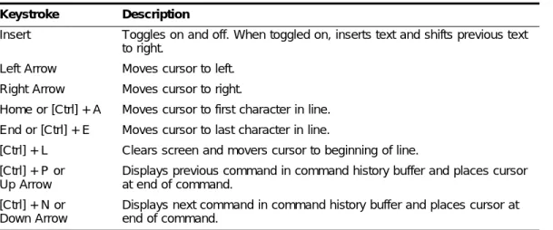
Line-Editing Keys
Table 13 describes the line-editing keys available using the CLI. Table 12: Command Syntax Symbols
Symbol Description
< > (angle brackets) Enclose a variable or value. You must specify the variable or value. For example, in the syntax
config vlan <name> ipaddress <ip_address>
you must supply a VLAN name for <name> and an address for
<ip_address> when entering the command. Do not type the angle brackets.
[ ] (square brackets) Enclose a required value or list of required arguments. One or more values or arguments can be specified. For example, in the syntax
use image [primary | secondary]
you must specify either the primary or secondary image when entering the command. Do not type the square brackets.
| (vertical bar) Separates mutually exclusive items in a list, one of which must be entered. For example, in the syntax
config snmp community [read-only | read-write] <string>
you must specify either the read or write community string in the command. Do not type the vertical bar.
{ } (braces) Enclose an optional value or a list of optional arguments. One or more values or arguments can be specified. For example, in the syntax
reboot {<date> <time> | cancel}
you can specify either a particular date and time combination, or the keyword cancel to cancel a previously scheduled reboot. If you do not specify an argument, the command will prompt, asking if you want to reboot the switch now. Do not type the braces.
Table 13: Line-Editing Keys
Keystroke Description
Accessing the Switch
Command History
ExtremeWare “remembers” the last 49 commands you entered. You can display a list of these commands by using the following command:
history
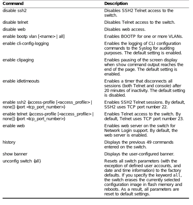
Common Commands
Table 14 describes common commands used to manage the switch. Commands specific to a particular feature are described in the other chapters of this guide.
Insert Toggles on and off. When toggled on, inserts text and shifts previous text to right.
Left Arrow Moves cursor to left. Right Arrow Moves cursor to right.
Home or [Ctrl] + A Moves cursor to first character in line. End or [Ctrl] + E Moves cursor to last character in line.
[Ctrl] + L Clears screen and movers cursor to beginning of line. [Ctrl] + P or
Up Arrow
Displays previous command in command history buffer and places cursor at end of command.
[Ctrl] + N or Down Arrow
Displays next command in command history buffer and places cursor at end of command.
Table 14: Common Commands
Command Description
clear session <number> Terminates a Telnet session from the switch.
config account <username> {encrypted} {<password>}
Configures a user account password. Passwords must have a minimum of 1 character and can have a maximum of 32 characters. User names and passwords are case-sensitive.
config banner Configures the banner string. You can
enter up to 24 rows of 79-column text that is displayed before the login prompt of each session. Press [Return] at the beginning of a line to terminate the command and apply the banner. To clear the banner, press [Return] at the beginning of the first line.
config ports <portlist> auto off {speed [10 | 100 | 1000]} duplex [half | full]
Manually configures the port speed and duplex setting of one or more ports on a switch.
config ssh2 key {pregenerated} Generates the SSH2 host key. Table 13: Line-Editing Keys (continued)
Common Commands
config sys-recovery-level [none | critical | all] Configures a recovery option for instances where an exception occurs in
ExtremeWare. Specify one of the following:
• none—Recovery without system reboot.
• critical—ExtremeWare logs an error to the syslog, and reboots the system after critical exceptions.
• all—ExtremeWare logs an error to the syslog, and reboots the system after any exception.
The default setting is none.
config time <date> <time> Configures the system date and time. The format is as follows:
mm/dd/yyyy hh:mm:ss
The time uses a 24-hour clock format. You cannot set the year past 2036.
config timezone <gmt_offset> {autodst | noautodst} Configures the time zone information to the configured offset from GMT time. The format of gmt_offset is +/- minutes from GMT time. Specify:
• autodst—Enables automatic Daylight Savings Time change.
• noautodst—Disables automatic Daylight Savings Time change. The default setting is autodst. config vlan <name> ipaddress <ip_address>
{<mask>}
Configures an IP address and subnet mask for a VLAN.
create account [admin | user] <username> {encrypted} {<password>}
Creates a user account. This command is available to admin-level users and to users with RADIUS command authorization. The username is between 1 and 32 characters, the password is between 0 and 16 characters.
create vlan <name> Creates a VLAN.
delete account <username> Deletes a user account.
delete vlan <name> Deletes a VLAN.
disable bootp vlan [<name> | all] Disables BOOTP for one or more VLANs. disable cli-config-logging Disables logging of CLI commands to the
Syslog.
disable clipaging Disables pausing of the screen display when a show command output reaches the end of the page.
disable idletimeouts Disables the timer that disconnects all sessions. Once disabled, console sessions remain open until the switch is rebooted or Table 14: Common Commands (continued)
Accessing the Switch
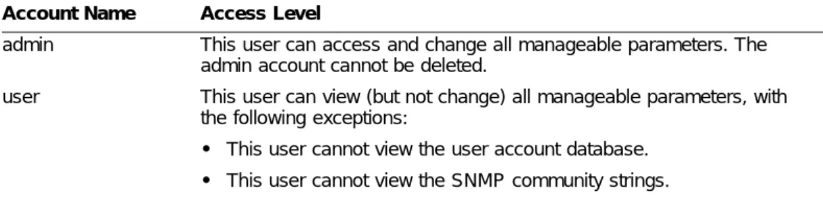
Configuring Management Access
ExtremeWare supports the following two levels of management:
• User
• Administrator
In addition to the management levels, you can optionally use an external RADIUS server to provide CLI command authorization checking for each command. For more information on RADIUS, see “RADIUS Client” in Chapter 5, “Managing the Switch”.
User Account
A user-level account has viewing access to all manageable parameters, with the exception of:
disable ssh2 Disables SSH2 Telnet access to the
switch.
disable telnet Disables Telnet access to the switch.
disable web Disables web access.
enable bootp vlan [<name> | all] Enables BOOTP for one or more VLANs. enable cli-config-logging Enables the logging of CLI configuration
commands to the Syslog for auditing purposes. The default setting is enabled. enable clipaging Enables pausing of the screen display
when show command output reaches the end of the page. The default setting is enabled.
enable idletimeouts Enables a timer that disconnects all sessions (both Telnet and console) after 20 minutes of inactivity. The default setting is disabled.
enable ssh2 {access-profile [<access_profile> | none]} {port <tcp_port_number>}
Enables SSH2 Telnet sessions. By default, SSH2 uses TCP port number 22.
enable telnet {access-profile [<access_profile> | none]} {port <tcp_port_number>}
Enables Telnet access to the switch. By default, Telnet uses TCP port number 23.
enable web Enables web server on the switch for
Network Login support. By default, the web server is enabled.
history Displays the previous 49 commands
entered on the switch.
show banner Displays the user-configured banner.
unconfig switch {all} Resets all switch parameters (with the exception of defined user accounts, and date and time information) to the factory defaults. If you specify the keyword all, the switch erases the currently selected configuration image in flash memory and reboots. As a result, all parameters are reset to default settings.
Table 14: Common Commands (continued)