Capacity Enhancement of Multiuser Wireless
Communication System through Adaptive
Non-Linear Pre coding
Dalveer Kaur, Neeraj Kumar
Department of Electronics & Communication Engineering, I.K Gujral Punjab Technical University, Jalandhar, India
Abstract: Multiuser multiple-input multiple-output (MIMO) nonlinear pre coding techniques face the issue of poor computational scalability of the size of the network. But by this nonlinear pre coding technique the interference is pre-cancelled automatically and also provides better capacity. So in order to reduce the computational burden in this paper, a definitive issue of MU-MIMO scalability is tackled through a non-linear adaptive optimum vector perturbation technique. Unlike the conventional (Vector Perturbation) VP methods, here a novel anterograde tracing is utilized which is usually recognized in the nervous system thus reducing complexity. The tracing of distance can be done through an iterative-optimization procedure. By this novel non-linear technique the capacity is improved to a greater extend which is explained practically. By means of this, the computational complexity is managed to be in the cubic order of the size of MUMIMO, and this mainly derives from the inverse of the channel matrix. The proposed signal processing system has been implemented in the working platform of MATLAB/SIMULINK. The simulation results of proposed communication system and comparison with existing systems shows the significance of the proposed work.
Keywords: adaptive optimum vector perturbation technique, anterograde tracing, multiple loop interference cancellation filters, equal probability (EP) algorithm.
1. Introduction
A wireless communications system incorporates a base station and a variety of terminal units comprising the storage unit and the communication unit which can be a mobile, radio transmission, microwave transmission, infrared and millimeter waves etc. The base station constitutes connections among sets of two or more of the mobile units so as to privilege private, full-duplex conversations that access within various set of terminal units [1]. The base station allots packet time slots for each active terminal unit to transmit, and dynamically diminishes the allocation per terminal unit only as the number of active terminal units increments [2]. The transmitter or the source transmits the message to the receiver or the destination through a secure channel that can be a satellite or a radio channel. The transmitter includes a microcontroller which transmits digital data to the receiver [3]. The data is encoded by the transmitter which is split into different streams and then the split encoded stream is transmitted to different transmit antennas. This output is received by the receiver where the decoder is obtained [4].
Some of the common challenges which tend to occur in the wireless communication network include the security vulnerabilities, some influence which can be made by the climatic conditions, interference from the other wireless devices etc. [5]. Apart from this the wireless network also includes problems such as the user mobility, noise limitations, spectrum limitations, energy limitations,
multipath propagation which lead to the complications such as the fading and ISI (Inter Symbol Interference) [6]. The spectrum limitations occur since the spectrum available is limited and is also regulated by international agreements. In case of the user mobility the system should be aware of the cell which the user is using every time. The noise is added to the transmitted signal during the transmission through a communication channel or the radio channel which reduce the signal quality [7]. The interference signal usually is capable of modifying the transmitted signal recognized in the channel between the transmitter and the receiver. The interfering signal obtained is decoded by the receiver and it is cancelled from the original message [8].
It is seen that the 4G wireless network, the LTE and CRN plays a vital role. There has been a developing pattern toward applying game theory (GT) to different building fields keeping in mind the end goal to take care of improvement issues with various contending elements/benefactors/players. Looks into in the fourth era (4G) remote net-work field additionally misused this propelled theory to defeat long-term evolution (LTE) difficulties, for example, asset portion, which is a standout amongst the most vital research points. Truth be told, an effective de-indication of asset assignment plans is the way to higher execution. Be that as it may, the standard does not indicate the advancement way to deal with executes the radio asset administration and in this way it was left open for thinks about. 4G-LTE radio asset distribution issue and its improvement [9].Cognitive radio networks (CRNs) have risen as a worldview tending to the issue of restricted range accessibility also, the range underutilization in remote networks by entrepreneurially abusing bits of the unused range by authorized essential clients. Routing in CRNs is a testing issue because of the PU exercises and versatility that are past the control of CRNs. Then again, vitality mindful routing is exceptionally essential in vitality limitation CRNs. Keeping in mind the end goal to outline a strong routing plan for portable cognitive radio specially appointed networks (CRANs), the requirements on lingering vitality of every CR client, dependability, and the assurance of Pus should furthermore be taken into account. In addition, multipath routing has awesome potential for enhancing the conclusion to-end execution of specially appointed networks. [10].
will be improved. Since there are large numbers of antennas, it is not possible to extend expensive and powerful hardware with small noise and distortion at the base station [12]. The techniques used to solve include the linear and non-linear pre coding. In existing paper the linear pre coding used is Zero-Forcing Coding (ZF) where an approximation to the distribution of the instantaneous per-terminal SNR of a ZF MU-MIMO system is presented to rectify the SNR (Signal to Noise Ratio) [13].
The linear Beam forming algorithm is also presented as a pre coding technique which is utilized for multi user Multi Input Single Output System (MU-MISO). A heuristic hybrid beam forming design was proposed that achieves a performance close to the performance of the fully digital beam forming baseline was designed also it establishes that if the number of RF chains is twice the total number of data streams, the hybrid beam forming structure can appreciate any fully digital beam former exactly, irrespective of the number of antenna elements [14]. The ZF and the Beam forming algorithms were also used hybrid and distributed implementations is facilitated by using Charnes-Cooper's transformation [15]. The nonlinear pre coding is identified better than the linear pre coding algorithm since the interference cancellation is done automatically and also it performs better. The nonlinear robust Tomlinson-Harashima pre coding outperforms by transforming the robust transceiver design problem into a difference of convex programming [16]. Capacity enhancements of multiuser wireless communication system through adaptive non-linear pre coding were addressed here. The outline of this paper is summarized as follows. Section 2 deals with related research problems. Section 3 discussed about the multiuser wireless communication system. Section 4 discussed about the simulation result and performance evaluation of this research and conclusion is stated in section 5.
2. Related Work
Some of the recent related works regarding multiuser wireless communication problems is discussed as follows Jin et al.[17] presented about the massive multiple-input multiple-output (MIMO) antenna system that use of an enormous number of base station (BS) antennas to handle a small number of user terminals (UTs) for spectral efficiency. Due to the unavoidable reuse of pilot sequences from UTs the performance was identified limited by pilot contamination. The performance of massive MIMO zero-forcing (ZF) systems was analyzed using the time-shifted pilot scheme by which the achievable sum rates and the associated SINRs for both forward link and reverse link were derived which was tend to work with both the limited and unlimited antenna cases. Moreover, a user scheduling algorithm LCFS was introduced based on the difference between the MIMO zero-forcing system and the time shifted pilot scheme which that promote the rate and fairness performance for conjugate pre coder. Due to the use of the time shifting pilot scheme the interference process which occurs in the MIMO system can be reduced to minor state. This process is mainly employed to improve the throughput of system. In turn there arise a drawback in LCF which fails to optimize the seek time.
Huberman et al. [18] have presented a single or multi-user Multiple Input-Multiple-Output (MIMO) Full-Duplex (FD)
pre coding transceiver structure relevant for single-carrier and Orthogonal Frequency Division Multiplexing (OFDM) systems. The cancellation of self-interference and for the combination of the forward beam forming with pre coding at the transmitter, its dimensionality was increased. A separate and a joint pre coding design was presented for sum-rate maximization where the joint designs make the benefit of Sequential Convex Programming (SCP).Other than the self-interference minimization the MIMO FDP structure that confess for different algorithms and optimization objectives. The separate FDP algorithm was identical to a self-interference canceller, where the cancellation is done by pre coding other than a self-interference while the joint FDP algorithms take procession of sequential convex programming. Although the separate and join designs offer an identical sum-rate performance; the amount of cancellation power was limited and further the joint FDP algorithm contribute performance improvements. Computational time and tradeoff are some factors are which needs improvement in FDP.
Christus masouros et al.[20] have considered a K link multiple-input multiple-output (MIMO) interference channel in which each link comprised of two full-duplex (FD) nodes exchanging information simultaneously in a bi-directional communication mode. The nodes in each pair suffered from self-interference occurred due to operating in FD mode, and inter-user interference from other links occurred due to accompanied transmission at each link. The transmitter and receiver filter design for Weighted Sum-Rate (WSR) maximization problem prone to sum-power constraint of the system at each node of the system. A low complexity alternating algorithm was recognized based on the relationship between WSR and Weighted Minimum-Mean-Squared-Error (WMMSE) problems for FD MIMO interference channels. The algorithm introduced was identified is not only applicable to FD cellular systems, in which a base station (BS) operating in FD mode serves multiple uplink (UL) and downlink (DL) users operating in half duplex(HD) mode, simultaneously along with FD MIMO interference channels. This provides acceptable spectral efficiency of optimized half duplex for SU-MIMO considerations anyhow there is a lagging in throughput of this system.
that reduces the transmit power over conventional techniques and the required QoS was guaranteed. By using this technique the optimization of conventional transmit power occurs which in turn saves small scale MISO downlink channels with data-aided optimization. Reduced CSI must to be considered as drawback in turn reduces throughput. Moretti et al. [21] had dealt with resource allocation scheme in the downlink of spatial multiplexing multiple-input– multiple-output (MIMO)-orthogonal frequency-division multiple-access (OFDMA) SDMA-MIMO-OFDMA systems. The problem of optimizing the transmitter and receiver processing matrices, the channel assignment, and the power allocation were concentrated with the objective of minimizing the total power consumption at the same time different quality-of-service (QoS) requirements are also satisfied. The introduced solution relied on the layered architecture in which MAI (Multiple Access Interference) was first removed by means of a THP technique operating at user level. A layered architecture was utilized where the users were first partitioned in different groups on the basis of their channel quality, and then channel assignment and transceiver design were addressed using a ZF-based approach. A Tomlinson–Harashima pre coder was utilized by which the multiuser interference among users belonging to different groups was removed at the base station (BS). This is mainly implemented to minimize the power consumption by satisfying the specific requirements of QOS given as the sum of the MSEs over the assigned subcarriers but further power consumption is needed and better transmit power. Thus in above techniques discussed there are some drawbacks in terms of computational time, capacity and throughput. All the above criterias are considered and overcome in our framework.
3. Capacity Enhancement of MU-MIMO
Wireless Communication System
The wireless communication system is meant for transmitting and receiving the voice or the data with the aid of electromagnetic waves. This information between the transmitter and the receiver is usually carried within a well-defined channel which imports a fixed frequency bandwidth and a capacity. The transmitter provides the message to the receiver through a secure communication channel. Also, the message sent by the transmitter is encoded by the encoder and then it is provided to the receiver. The receiver decodes the signal and eliminates the interference which is send along with the encoded message.
The wireless communication system includes the complications such as the security vulnerabilities, low capacity, high complexity, low speed. Also, for setting the infrastructure it requires high cost, it is also influenced by the climatic conditions, physical obstructions etc. Interference is another complication which is identified by the effect of nearby wireless devices. The nonlinear pre coding rectifies the above-mentioned problems along with the cancellation of the interference and enhances the capacity. In order to solve these problems the adaptive optimum vector perturbation technique along with multiple filters is presented.
Figure 1 shows the process flow of the proposed approach. The proposed methodology describes about the MU-MIMO which includes multiple transmitter, multiple receiver and communication channel. Initially transmitter transmits the
signal to the receiver through the communication channel by pre coding process for which adaptive optimum vector perturbation technique is utilized. In this algorithm the Euclidean distance is replaced by utilizing anterograde tracing. After pre coding, scheduling is done by utilizing equal probability (EP) algorithm then the pre coded signal is fed as input to the communication channel, where communication channel adds noise along with interference.
Scheduling
Communication channel Post coding with adaptive
vector perturbation Noise filter Precoding with adaptive vector
perturbation MU-MIMO Transmitter
MU-MIMO Receiver
Figure 1: An MU-MIMO System with Adaptive Vector Pre coding
After that multiple loop interference cancellation filter is utilized to cancel the interference and also the capacity is enhanced also the Gaussian noise occurred is also reduced simultaneously. The pre coded message from the transmitter is post coded in the receiver and the corresponding message is obtained. The multiple receivers have some complications regarding the recognition of appropriate receiver and finally the corresponding recipient sends the message receipt after signal delivery.
3.1. Channel model for MU-MIMO wireless communication system
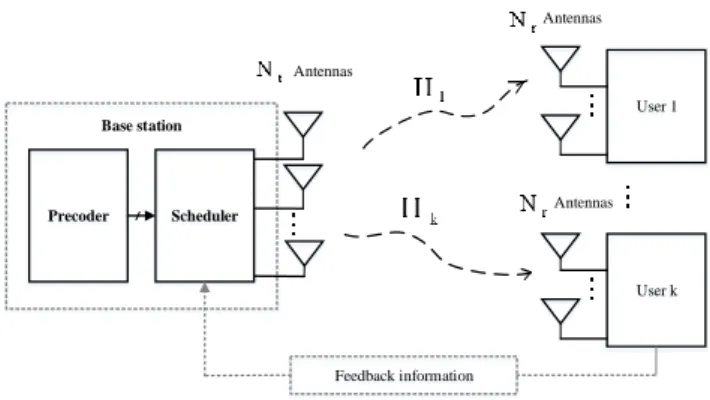
Precoder Scheduler
User 1
User k
Base station
Antennas
Antennas
Antennas
Feedback information
Figure2. Channel model for MU-MIMO wireless communication system
Figure 2 shows the Channel model for MU-MIMO wireless communication system. Initially the transmitter transmit the input signal T and the received signal at receiver is given as,
HT
R
(1) Consider a MIMO multiuser transmission system, the coupling between the transmitter and receiver can be modelled usingk
HT
samples of the complex receive-array output and
k
is anS
R
n
n
matrix containing zero-mean complex Gaussian noise and is added in the communication channel. It is often useful to investigate the structure of the channel matrix and the mean-square attenuation independently. This can be achieved by studying the root-mean-square normalized channel matrixH
m
1
H
(3)R T
2
2
n
n
H
m
F(4)
Where
m
2is the mean-square transmitter-to-receiver attenuation,H
is the normalized channel matrix, andF
indicates the Frobenius norm. The input signal from the transmitter is fed to the pre coding section.
3.2 Adaptive optimum vector perturbation technique for pre coding
Pre coding is a technique which misuses transmit diversity by weighting information stream, i.e. the transmitter transmits the coded information to the receiver in order to the pre-learning of the channel. The receiver is a simple detector which does not have any knowledge about channel side information.
In multi-user MIMO, a multi-antenna transmitter communicates at the same time with multiple receivers (each having one or multiple antennas) known as space-division multiple access (SDMA). Pre-coding algorithms for SDMA systems can be sub-separated into linear and nonlinear pre coding types. Linear pre coding approaches as a rule achieve sensible performance with much lower complexity, however the interference cannot be canceled automatically and practically capacity achieving algorithms are nonlinear. It is designed in light of the concept of dirty paper coding (DPC), which demonstrates that any known interference at the transmitter can be subtracted without the punishment of radio resources if the ideal pre-coding scheme can be connected on the transmit signal.
This can be seen as a multi-objective optimization issue where each objective corresponds to maximization of the capacity of one of the clients. For simplify this problem we are using adaptive optimum vector perturbation. Usually the perturbation technique uses the Euclidean distance to measure the distance between the transmitter and receiver where the complexity increases. Here we replace the Euclidean distance by utilizing Anterograde tracing by which the complexity is reduced to a greater extend by iterative processing and also the capacity enhancement is also made alternatively and is explained mathematically. It traces the distance between the transmitter and the receiver. This anterograde tracing was usually recognized in the nervous system which is used to trace the axonal projections from the source i.e. the cell body to the point of termination i.e. synapse perfectly and also allow mapping of connections between neurons. The iterative tracing is done with the help of the objective function and hence reduces the complexity and the performance is improved by including multiple iterations also reducing the coverage problems.
Generally in the Euclidean distance estimation the minimum mean square error is utilized where some information loss occurs but in the anterograde tracing sigmoid function is utilized that derives a maximum entropy level i.e. by information theory all the information given through the communication channel is given clearly to the receiver. Non-linear sigmoid function applied to the signal by anterograde tracing before transmitting in order to express the derivative in terms of mathematical function such as
))
(
1
)(
(
)
(
T
if
T
if
T
if
(5) wheref
(
T
i)
is a sigmoid function.2
)
1
(
)
(
i i i
T
T
T
f
(6)Consider transmit vector constructed from the user data vector
v
[
v
1,
v
2,...
v
N]
D
N1 and perturbation vectoru
[
u
1,
u
2,...
u
N]
D
N1 such that,
T
v
u
(7) Where,
is a positive scalaru
is a complex Gaussian integer vector that is,u
i
{
b
ja
b
,
a
Y
},
.
,...
1
N
i
Transmit vectorT
is pre coded by the pre coder matrixZ
D
PN to produce pre coded symbol vectorc
[
c
1,c
2,...
c
P]
D
P1 that isc
ZT
. Consequently, each user for example thei
th
user receives the signalR
i
D
over the channelCh
i
D
P1 contaminated by the additive white Gaussian noisek
i
D
andk
i~
Cn
(
0
,
K
o)
.Cn
(
0
,
)
, denotes a zero-mean circularly symmetric complex Gaussian (CSCG) random variable with variance
. We consider a spatially uncorrelated Rayleigh fading environment that is the elements ofCh
i is independent and identically distributed)
1
,
0
(
Cn
. As a result the received signal ofi
th
useri
R
can be written as,i H i i
Ch
c
k
R
,i
1
,...
N
(8) The user scalesR
i by the normalization factor
(
0
)
that has been chosen to satisfy the base station power constraint. Therefore the scaled received signalT
i
R
i^
,
N
i
1
,...
can be given by,
T
Hc
k
^
(9) Where
H
[
Ch
1,
Ch
2,...
Ch
n]
H,k
[
k
1,
k
2...
k
n]
and
]
ˆ
,...
ˆ
,
ˆ
[
ˆ
2
1
T
T
NT
, is chosen to provide symmetric decoding regions around constellation points and the choice2
2
max
C
where,
max
C
is the absolute value of the value of the largest magnitude constellation symbol and
is the spacing between constellation points, serves this purpose. With this choice for
, each user is able to apply modulo function(.)
f
onT
i
independently (i.e., without cooperation) and remove
u
i without knowing its value. Here,
(
b
)
b
[(
b
2
)
]
f
where
.
denotes thelargest integer less than or equal to its argument. Note that
(.)
f
is independently performed on both real and imaginary components ofT
i
.
3.3 Equal probability (EP) algorithm for scheduling
Assume that the BS schedules in each slot on each beam where a single user is randomly chosen among the positive feedback for that beam reported.. According to the conservative rate assignment, the average sum-rate is formulated as,
j
J j L l S J j j
SUM R P jl
R
1 log , 2 1 1 1 (10) Depends on the probability of scheduling the user
j
on beaml
, here rewritten as
jl j
J d l Sp
d
j
d
P
l
j
P
1 ,
1
|
,
(11)Where
P
l
d
|
j
, is the probability thatd
users (out ofJ
) exceed their thresholds on beaml
conditioned to the event that the userj
exceeds its threshold on the same beaml
, andp
j,l
j
is the probability that the SINR of userj
on beaml
exceeds the threshold
j. The beam forming randomization of opportunistic strategy implies that the SINR probability density function experienced by each user depends only on the channel powerp
jand on the receiver characteristics (namely the number of antennasNo
land the receiver’s combining scheme), but it is independent of the beam indexl
, so thatp
j,l
j
p
j,l
j
. Hence, all the beams have the same (average) performance and thus the beam index m will be omitted. The sum-rate (11) reduces to:
j j
j
J j J j SUM p d j d P LR
1 log 1 | 2 1 1 (12) The drawback to sum-rate (12) maximization is the need to set up a centralized optimization problem to evaluate all the optimal thresholds
jin addition to the lack of a manageable expression forP
d
|
j
. The nearly-optimal distributed threshold estimation algorithm described below guarantees the evaluation of a set of thresholds
jfor theasymptotical maximization of the sum-rate based on local estimates carried out by each MS independently.
The EP threshold setting algorithm forces all the
J
users to set their SINR threshold on any of the beams according to the system-defined feedback loading probability
j j
p
F
(13) Once every MS is aware of the system-defined feedback probability valueF
, it can locally evaluate its SINR threshold by solving (13) for
j. From a practical point of view, it is convenient to redefine (13) according to the scheduling outage probability (i.e., the probability that no user exceeds its threshold on a given beam and thus the beam is not used):
J outF
P
1
(14) Sum-rate (12) and thresholds{
j}
can thus be rewritten in terms of outage probabilityP
outonce it is known the number of usersJ
. Channels independence implies that the scheduling probability is the same for all the users so thatJ
P
P
j
P
S
S
1
out)
(
(15)Therefore, when constraint (13) holds the resources are shared in a fair way among all the
J
MSs with respect to the scheduling probabilities. The achievable sum-rate (12) under EP scheduling constraint (13) reduces to
J j out j out SUMP
J
P
L
R
1 21
log
1
(16) Where we highlighted the dependence of
jfromP
out. The sum-rate maximization problem is thus reduced to optimizing the system-defined outage probability valueP
out in (16). As it will be shown in the next paragraph, the nearly optimal value ofP
out (or equivalentlyF
according to (14)) can be locally evaluated by the BS and all the MSs without any need for dedicated signalling.After scheduling the pre coded signal is fed to the communication channel. Then the interference will acquires. The interference is anything which modifies, or disrupts a signal as it travels along a channel between a source and a receiver. The interference matrix is E,
]
,...
[
E
1,E
2E
PE
Then the output from thecommunication channel is
E
k
Hc
I
(
)
(17) 3.4 Multiple loop interference cancellation filterWe define 1
2 ,
1 ,... ]
[ P P D T T T
T and
1 2
,
1 ,... ]
[ P P D R R R
R , and these are the vector of the data
signal at the BS and the vector of the received signal at the MSs, respectively. After pre coding the signal changes in the form of
i i R
T
^
matrix
C
. Note that the dimension of matricesY
andC
areM
M
andN
N
, respectively.
]
,...
[
E
1,E
2E
PC
(18)The BS transmits data signal
T
to the MS. The channel receives the signal and then cancels the loop interference
]
,...
[
E
1,E
2E
PE
by usingC
. The signal after the loop interference cancellation, can be written as
C
E
k
Hc
f
(
)
(19) That complication includes the interference cancellation that also comprises loop interference caused by coupling, ILS (Integer Least Square), coverage problems. After loop interference cancellation, the signal is processed using weighting matrixW
and then transmitted to the MSs. The received signal at the MSs can be written ask
Hc
f
(20) Wherek
is the vector of noise at the MSs. Then the noise is removed by usingk
00
k
k
Hc
f
(21) The received signal at the MSs can be rewritten asHc
f
(22) 3.5 Adaptive optimum vector perturbation technique for Post codingThe pre coded message from the transmitter is post coded in the receiver and the corresponding signal is obtained. By the usage of the adaptive non-linear vector perturbation technique the corresponding capacity improvement is made in the receiver side. The multiple receivers have some complications regarding the recognition of appropriate receiver. Finally the corresponding recipient sends the message receipt after signal delivery. It is a reverse process of pre coding. Here the matrix
Z
and
normalization factor can be removed. Thus the receiver gets the original signal as output.The received signal at the receiver can be rewritten as
Hc
R
(23) Wherec
ZT
then the received signal isHZT
R
(24) In the post coding we remove the normalization factor and pre coded matrix.
Z
HZT
R
(25) Then we get the original signal as outputHT
R
(26) 3.6 Multiuser MIMO CapacityThe multiuser system capacity enhancement made in the receiver side is then a simple extension of channel capacity for single-input single-output channels with memory can be expressed mathematically as
]
...
,
[
]
,...
,
[
det
log
1
2 1 2 1 1 2 n N vP
k
k
k
I
T
T
T
L
a
C
(27)where
v
is a single user.L
is Data transmitted in blocks of symbols of length.det(.)
, represents the determinant of the input matrix
takes the modulus of every entry of the input matrix.MIMO and the upper bound are based on diagonalization and uncoupled channels result, capacity is readily calculated (27). To allow performance comparisons in addition to bit-error rate (BER), we introduce an approximate capacity measure. Such a measure is based on the use of the Gaussian assumption which implies that the interference becomes Gaussian distributed when there are several users. Suppose that we have a linear model similar
R
HT
k
.where
k
is the undesired signal vector which can be correlated noise. Assuming thatk
is Gaussian with covariance matrix[
k
1,
k
2...
k
n]
and is uncorrelated withT
. From (27), we know that the capacity is of the form)
]
...
,
det([
)
]
,...
,
det([
log
2 1 2 1 2 n Nk
k
k
T
T
T
Ca
(28)After some manipulation, (28) can be simplified as
det
)
]
,...
,
[
H
(
det
log
1 2 2 NT
T
T
Ca
(29)The multiuser MIMO channel capacity is just a simple extension of (29). Using the system model defined in Section 3.1, the total capacity per transmission of the Pth user link,
P
Ca
, can be found byP P P P
T
Ca
det
)
H
(
det
log
P2 (30)
where
I
k
T
P v P P P P
1 PP
H
(31)As a result, the overall system spectral efficiency of a multiuser MIMO system is given by
mission
bits/trans
1
1
v P PCa
L
a
C
(32)The above capacity expression is generally not exact, but is a good approximation when the number of users or the number of transmits antennas is large by central limit theorem. Because this approximate capacity expression inherits the relations between the co-channel signals, capacity based on (32) is still used for primary performance comparison even for the case when the number of users and the number of transmit antennas are small.
Table 1. Nomenclature
VARIABLES EXPLANATION
R
receive-array outputH
channel matrixT
transmit array vectorR
n
number of receive antennaT
n
number of transmit antennaS
n
number of samplesm
mean-squaretransmitter-to-receiver attenuation
u
perturbation vectorv
user data vector
positive scalarD
channel side informationquantization
Z
Pre coder matrixY
Complex functiona
imaginary componentsb
Real componentsc
Pre coded symbol vector)
,
0
(
Cn
zero-mean circularlysymmetric complex Gaussian
normalization factor^
T
scaled received signal
(.)
f
modulo function
C
max
absolute value of the value of the largest magnitudeconstellation symbol
spacing between constellationpoints
SUM
R
average sum ratej
userl
Beam index
j
l
P
S,
Probability of scheduling theuser
j
on beaml
.
d
j
P
l|
probability thatd
users (outof
J
) exceed their thresholdson beam
l
conditioned to theevent that the user
j
exceedsits threshold on the same beam
l
jl j
p
,
probability that the SINR ofuser
j
on beaml
exceeds thethreshold
jj
p
channel powerl
No
number of antennasF
feedback probability valueout
P
outage probabilityE
Interference matrixC
cancelling matrixW
Weighted matrixL
symbols of lengthCa
channel capacity4. Simulation results and discussion
This section presents the simulation results in the proposed research work. Our proposed work has been implemented in the MATLAB/SIMULINK platform. The proposed methodology describes about the MU-MIMO which includes multiple transmitter, receiver and communication channel. The transmitter transmits the signal to pre coding process. For pre coding adaptive optimum vector perturbation technique will be utilized. In this algorithm we replace the Euclidean distance by utilizing anterograde tracing. After pre coding, scheduling will be done by utilizing equal probability (EP) algorithm. Then the pre coded signal fed as input to the communication channel, where the communication channel adds noise along with the interference. After that the multiple loop interference cancellation filter is utilized to cancel the interference and also the capacity will be enhanced also the Gaussian noise occurred will also be reduced simultaneously. The pre coded message from the transmitter will be post coded in the receiver and the corresponding message will be obtained. The multiple receivers have some complications regarding the recognition of appropriate receiver. Finally the corresponding recipient sends the message receipt after signal delivery. The simulation outputs obtained from the proposed design is presented in the upcoming sections.
4.1 Simulink model of the proposed system
The Simulink model design of the proposed communication system is shown in figure 3 (on the last page). The proposed methodology describes about the MU-MIMO which includes multiple transmitter, receiver. The multi transmitter connected to the multi receiver through a communication channel. Here the transmitter side pre coding and the receiver side post coding will be done.
4.2 Proposed System Results
In our proposed work the transmitter transmit the signal to receiver through communication channel. The input signal fed as the input for pre coding process. The input signal from the transmitter is shown in the figure 4. In this work we considered 6 input signals.
utilizing equal probability (EP) algorithm. The pre coded signal is shown in the figure 5.
Figure 4. The input signal from the transmitter
Figure 5. The pre coded signal
After pre coding the pre coded signal is scheduled using equal probability (EP) algorithm. Then it is fed as the input to the communication channel. In this communication channel the interference and Gaussian noise will be added with the pre coding signal. After this signal fed as the input for filtering. The output from the communication channel is shown in figure 6.
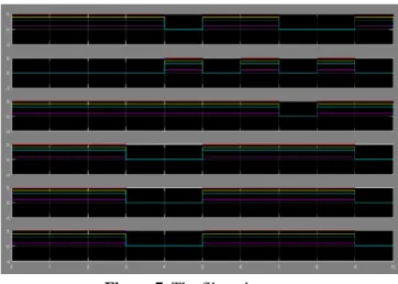
Figure 6. Output from the communication channel The output from the communication channel is filtered by using multiple loop interference cancellation. Utilizing this filter the interference will cancelled also the capacity will be enhanced also the Gaussian noise occurred will also be reduced simultaneously. The filtered output is shown in the figure 7.
Figure 7. The filtered output
The pre coded message from the transmitter will be post coded in the receiver and the corresponding message will be obtained. It is the reverse process of pre coding. The multiple receivers have some complications regarding the recognition of appropriate receiver. Finally the corresponding recipient sends the message receipt after signal delivery. The simulation outputs obtained from the proposed design is presented in the upcoming sections. The output signal from the receiver is shown in the figure 8.
Figure 8. The output signal 4.3 Performance and evaluation
In this work Performance such as throughput, BER, delay, SINR, complexity, capacity and SNR are calculated. Then it is compared with the existing methods.
4.3.1 Throughput
Throughput is the rate of successful message delivery over a communication channel. Throughput is usually measured in bits per second (bit/s or bps) as in (33).
Throughput=
Time bits of
Number (33)
4.3.2 Bit error rate (BER)
In transmission, the number of bit errors is the number of received bits of a data stream over a communication
channel that have been altered due
to noise, interference, distortion as in (34). BER=
sent bits of Number
error of Number
4.3.3 Delay
It is a transmission delay. It is the amount of time required to push all the packet's bits into the wire as in (35).
Delay=
ion transmiss of
Rate
bits of Number
(35)
4.3.4 SNR (Signal Noise Ratio)
It is a signal to noise ratio between the input and output signals.
SNR=
Noise receiver in Signal
4.3.5 SINR (Signal to Interference Noise Ratio)
The signal to noise interference ratio is described as the ratio of the power of incoming signal (
P
) from the transmitter divided by the sum of the interference signal (I
) and the noise (N
) as in (36).N I
P
SINR (36)
4.3.6 Capacity
Along with all other parameters the capacity of the MU-MIMO system is also considered in order to verify the effectiveness of the system. For practical applications the capacity is calculated by using by the formula as in (30, 31 and 32). As in (30) the capacity of each and every signal is calculated individually and thus capacity for every users are recorded. Then as in (32) the total capacity value is calculated by taking the summation of the values obtained.
4.3.7 Complexity
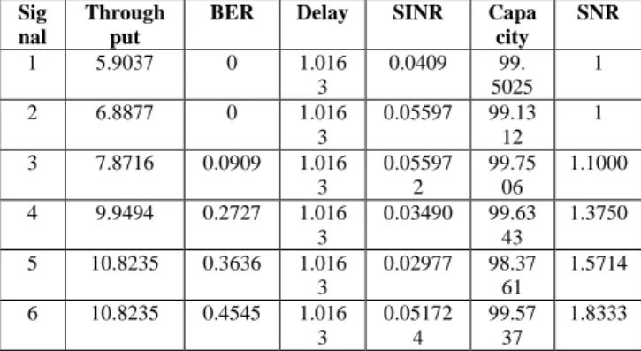
The complexity of the proposed method is reduced to a greater extend since the proposed anterograde tracing methods in most cases identify the receiver without any iterations and thus implementing a better output. The complexity is measured with the aid of delay. The BER, Throughput, delay, SINR, Capacity and SNR of our proposed work is shown in the table 1 and figure 8.
Table 2. BER, Throughput, SINR, Capacity, SNR and Delay Sig
nal
Through put
BER Delay SINR Capa city
SNR
1 5.9037 0 1.016
3
0.0409 99.
5025 1
2 6.8877 0 1.016
3
0.05597 99.13
12 1
3 7.8716 0.0909 1.016
3
0.05597 2
99.75 06
1.1000
4 9.9494 0.2727 1.016
3
0.03490 99.63
43
1.3750
5 10.8235 0.3636 1.016
3
0.02977 98.37
61
1.5714
6 10.8235 0.4545 1.016
3
0.05172 4
99.57 37
1.8333
Figure 9. Proposed parameters for SNR, BER, Throughput, SINR and Capacity
4.4 Comparison Results
Our proposed signal processing system is compared with the existing system. This proposed approach throughput, BER, SINR, complexity, throughput, capacity and SNR is compared with the existing VP (Vector perturbation) approaches. The given parameters are compared with the existing pre coding approaches such as the Robust Minimum Mean Square Error Pre coding (RRMMSEP), Robust Multi Branch Tomlinson–Harashima Pre coding (RMTHP), Lattice-Reduction Aided successive Optimization Tomlinson-Harashima Pre coding (LRASOTHP), Block Diagonalization with Limited Feedback (BDP), Minimum Mean Square Error Pre coding (MMSEP), Minimum Mean Square Error (MMSE), Distributed Block Diagonalization with Selective Zero Forcing (DBP-ZP), Multi-Branch Tomlinson-Harashima Pre coding (MBTHP), Coordinated Multi-Point (CoMP), Multi-Cell Block Diagonalization Pre coding (MC-BDP). The comparison graphs for all the parameters are shown in the corresponding figure given as the [10], [11], [12], [13], [14] and [15].
Figure 10. Comparison for Throughput 7
8 9
PROPOSED MCBDP
TH
R
O
UG
H
PUT
VARIOUS METHODS
Figure 11. Comparison for BER
In this work the SNR is high when compared with the existing methods. The comparison graph for SNR is shown in the figure 12.
Figure 12. Comparison for SNR
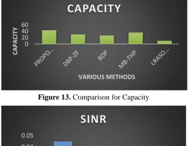
In this proposed method the capacity is high when compared with the existing methods. The comparison graph for capacity is shown in the figure 13 providing a better capacity value. In this proposed method the SINR is high when compared with the existing methods. The comparison graph for SINR is shown in the figure 13 providing a better output.
Figure 13. Comparison for Capacity
Figure14. Comparison for SINR
5. Conclusion
In this paper Multiuser multiple-input multiple-output (MUMIMO) nonlinear pre coding with adaptive optimum vector perturbation technique is presented. It traces the distance by using anterograde tracing. This anterograde tracing was usually recognized in the nervous system.This trace the distance through an iterative-optimization procedure. Each iteration performs vector perturbation over two optimally selected subspaces. By this means, the computational complexity is managed to be in the cubic order of the size of MUMIMO, and this mainly comes from the inverse of the channel matrix. Our proposed signal processing system has been implemented in the working platform of MATLAB/SIMULINK. This proposed approach obtained high throughput 10.8235, with less BER 0.0909, delay 1.0163, SINR 0.0448, capacity 99.6504, SNR 1.00 and also less complexity when compared with the existing VP approaches.
References
[1] Dahlman, Erik, Gunnar Mildh, Stefan Parkvall, Janne Peisa, Joachim Sachs, Yngve Selén, and Johan Sköld, “5G wireless access: requirements and realization,” IEEE Communications Magazine, Vol. 52, No. 12, pp.42-47, 2014.
[2] Larsson, G. Erik Ove Edfors, Fredrik Tufvesson, and L. Thomas Marzetta. “Massive MIMO for next generation wireless systems,” IEEE Communications Magazine, Vol. 52, No. 2, pp.186-195, 2014.
[3] Ren, Fang, Juhao Li, Tao Hu, Ruizhi Tang, Jinyi Yu, Qi Mo, Yongqi He, Zhangyuan Chen, and Zhengbin Li, “Cascaded mode-division-multiplexing and time-division-multiplexing passive optical network based on low mode-crosstalk FMF and mode MUX/DEMUX,” IEEE Photonics Journal, Vol. 7, No. 5, pp.1-9, 2015. [4] Zou, Yulong, Jia Zhu, Xianbin Wang, and C.M. Victor
Leung, “Improving physical-layer security in wireless communications using diversity techniques,” IEEE Network, Vol. 29, No. 1, pp.42-48, 2015.
[5] Yang, Nan, Lifeng Wang, Giovanni Geraci, Maged Elkashlan, Jinhong Yuan, and Marco Di Renzo, “Safeguarding 5G wireless communication networks using physical layer security,” IEEE Communications Magazine, Vol. 53, No. 4, pp.20-27, 2015.
[6] Bi, Suzhi, Chin Keong Ho, and Rui Zhang, “Wireless powered communication: opportunities and challenges,” IEEE Communications Magazine, Vol. 53, No. 4, pp.117-125, 2015.
[7] Razaviyayn, Meisam, Maziar Sanjabi, and Zhi-Quan Luo, “A stochastic successive minimization method for nonsmooth nonconvex optimization with applications to transceiver design in wireless communication networks,” Mathematical Programming, Vol. 157, No. 2, pp.515-545, 2016.
[8] Ng, Derrick Wing Kwan, S. Ernest Lo, and Robert Schober, “Multiobjective resource allocation for secure communication in cognitive radio networks with wireless information and power transfer,” IEEE Transactions on Vehicular Technology, Vol. 65, No. 5, pp.3166-3184, 2016.
[9] S. Oulaourf, A. Haidine, A. Aqqal, and H. Ouahmane, “Review on Radio Resource Allocation Optimization in 0
0.5 1
BE
R
VARIOUS METHODS
BER
0 0.5 1 1.5
SNR
VARIOUS METHODS
SNR
0 20 40 60
C
A
PA
C
ITY
VARIOUS METHODS
CAPACITY
0 0.01 0.02 0.03 0.04 0.05
PROPOSED MCBDP LRASOTHP
SIN
R
VARIOUS METHODS
LTE/LTE-Advanced using Game Theory,” International Journal of Communication Networks and Information Security (IJCNIS), Vol.9, No.1, pp.117-153, 2017.
[10] S.M. Kamruzzaman, X. Fernando, and M. Jaseemuddin, “Energy aware multipath routing protocol for cognitive radio ad hoc networks,” International Journal of Communication Networks and Information Security, Vol.8, No.3, pp.187, 2016.
[11] Björnson, Emil, Luca Sanguinetti, Jakob Hoydis, and Mérouane Debbah, “Optimal design of energy-efficient multi-user MIMO systems: Is massive MIMO the answer,” IEEE Transactions on Wireless Communications, Vol. 14, No. 6, pp.3059-3075, 2015. [12] Choi, Junil, Jianhua Mo, and W. Robert Heath, “Near
maximum-likelihood detector and channel estimator for uplink multiuser massive MIMO systems with one-bit ADCs,” IEEE Transactions on Communications, Vol.64, No. 5, pp.2005-2018, 2016.
[13] Tataria, Harsh, J. Peter Smith, J. Larry Greenstein, and A. Pawel Dmochowski, “Zero-Forcing Precoding Performance in Multiuser MIMO Systems with Heterogeneous Ricean Fading,” IEEE Wireless Communications Letters, Vol. 6, No. 1, pp.74-77, 2017. [14] Sohrabi, Foad, and Wei Yu, “Hybrid digital and analog
beam forming design for large-scale antenna arrays,” IEEE Journal of Selected Topics in Signal Processing, Vol.10, No. 3, pp.501-513, 2016.
[15] Vu, Quang-Doanh, Le-Nam Tran, Ronan Farrell, and Een-Kee Hong, “Energy-efficient zero-forcing precoding design for small-cell networks,” IEEE Transactions on Communications, Vol.64, No. 2, pp.790-804, 2016.
[16] Q. Li, Q. Zhang, and J. Qin, “Robust Tomlinson– Harashima Precoding With Gaussian Uncertainties for SWIPT in MIMO Broadcast Channels,” IEEE Transactions on Signal Processing, Vol. 65, No.6, pp.1399-1411, 2017.
[17] Jin, Shi, Xiaoyu Wang, Zheng Li, Kai-Kit Wong, Yongming Huang, and Xiaoyong Tang, “On massive MIMO zero-forcing transceiver using time-shifted pilots,” IEEE Transactions on Vehicular Technology, Vol. 65, No. 1, pp.59-74, 2016.
[18] Huberman, Sean, and Tho Le-Ngoc, “MIMO full-duplex precoding: A joint beam forming and self-interference cancellation structure,” IEEE Transactions on Wireless Communications, Vol. 14, No. 4, pp.2205-2217, 2015. [19] Cirik, Ali Cagatay, Rui Wang, Yingbo Hua, and Matti Latva-aho, “Weighted sum-rate maximization for full-duplex MIMO interference channels,” IEEE Transactions on Communications, Vol. 63, No. 3, pp.801-815, 2015.
[20] Masouros, Christos, and Gan Zheng, “Exploiting known interference as green signal power for downlink beamforming optimization,” IEEE Transactions on Signal Processing, Vol. 63, no. 14, pp.3628-3640, 2015. [21] Moretti, Marco, Luca Sanguinetti, and Xiaodong Wang,