Energy Efficient Secure & Privacy Preserving Data Aggregation
for WSNs
Irfana Memon1
Q.U.E.S.T, Nawabshah, Pakistan.
Corresponding Author: Email: [email protected]
Abstract
The aim of this research work is to enhance wireless sensor network life time via reducing communication overhead. Sensor nodes have limited resources specially energy resource which is difficult or impossible to change/replace. As communication is by far the most energy consuming aspect in WSNs, one of the main goals to save energy is therefore to reduce communication overhead.
Data aggregation techniques reduce number of transmitted messages and enhance WSNs lifetime. In many WSNs applications, data aggregation while preserving data security and privacy becomes hot issue because of the personal data.
In the paper, we present an approach to aggregate data in energy efficient and secure manner for WSNs, which is called Energy efficient Secure & Privacy Preserving data Aggregation for WSNs (ESPPA). The technique “slicing and mixing’’, is implemented to provide privacy. To show the superiority of our proposed ESPPA scheme, we compare it with an existing “slicing and mixing" based scheme (i.e., SMART (Slice-Mix-AggRegaTe) scheme). Through simulation results, we demonstrate that our presented approach ESPPA scheme effectively preserve data privacy, and has significantly less communication overhead than the SMART.
Key Words
: WSNS; Information aggregation; Security and privacy.1. Introduction
Wireless sensor networks (WSNs) are set of many sensors having limited resources. WSNs aim at making communication between sensor nodes feasible without any infrastructure support. Due to the characteristics of low cost and easy to deploy, WSNs have attracted more and more attention and have been used in many different applications, like battlefield surveillance, environmental monitoring, healthcare, home monitoring. Previous studies such as [15] have shown that message transmission among sensor nodes consume a big part of the full energy expenditure in the WSNs. Therefore, finding an efficient approach to reduce data transmission in the network is particularly important as it saves energy.
Data aggregation [2, 8, 23, 10, 7, 5] is an energy saving technique via combining incoming messages and eliminating redundant data at some special node, called aggregators. The aggregated information is sent to the remote Sink (base station). As wireless communication can be overheard and WSNs may be deployed in unsecured, hostile or
un-trusted areas, data security in WSNs is a crucial issue. Security in WSNs can be broadly classified into two main types, external security and internal security [7]. In external security (also called confidentiality), sensed data is protected from outsider adversaries (i.e., adversaries which are not part of the network). These outsider adversaries are only able to overhear (eavesdrop) the wireless links to obtain sensitive information from the WSN. Data confidentiality protection in WSNs has been extensively studied [22, 19, 21, 24, 6, 3, and 11]. Most of the proposed approaches rely on message encryption. In internal security (also called privacy), sensed data is protected from the internal adversaries (i.e., adversaries have stole the key material stored on the participating nodes) as well as from trusted participating sensor nodes. An attacker may easily capture a sensor node and get stored information, because of lack of tamper-resistant. Privacy of data in a WSN has received less attention than confidentiality. In [17], authors analysis privacy-preserving techniques used in WSNs. Data aggregation and data security & privacy should be considered together in WSNs. Therefore, it becomes a hot research issue in WSNs
technology. Some of approaches have been proposed by researchers regarding this issue. Review of existing secure and privacy-preserving data aggregation for WSNs can be found in [4, 20].
He, W. et al., [12] have proposed SMART (Slice- Mix-AggRegaTe) scheme for privacy preserving data aggregation. SMART is based on the “slicing and mixing" technique, in which each node divides its private data into a fixed number of pieces (say, J pieces) and sends those data pieces to randomly selected J -1 nodes (the selected nodes are within h hops from the node). Node keeps one piece itself. Each node aggregates the data pieces that are received from other nodes. However, the “slicing and mixing" technique in the SMART approach suffers from high communication cost which increases collision.
He, W. et al., also proposed another approach i.e., iPDA scheme in [13]. iPDA is modified version of SMART to achieve integrity by using two disjoint aggregation trees. Each sensor node sends its private data on two disjoint aggregation trees and aggregate data along them. Integrity is achieved via comparison of received aggregated result along two trees. Although iPDA improves SMART by providing data integrity, iPDA has the following disadvantages: (1) it is unrealistic to check integrity at BS via comparison of received aggregation result along the two trees. Because WSNs are un-reliable, it cannot be sure that all nodes respond to all messages, and (2) iPDA scheme suffers from high communication overhead (i.e., double of the SMART scheme) due to “slicing and mixing" technique and message transmission along two aggregation trees.
Li et al. in [26] have proposed another improvement of the SMART scheme, named EEHA: Energy-Efficient and High-Accuracy scheme. EEHA improves the performance of privacy preserving data aggregation by dividing the sensor nodes into two types: leaf nodes and intermediate nodes. The slicing and mixing technique is only implemented on leaf nodes. The intermediate nodes do not slice data into pieces and only aggregate their private data pieces received from leaf nodes into new aggregated data. EEHA scheme achieves data confidentiality and privacy through encryption and slicing & mixing technique. EEHA has less communication overhead
than the SMART, because slicing and mixing technique is only implemented on leaf nodes. However, EEHA has the same drawbacks as SMART: lack of data integrity, poor resilient to node compromise attack, the excessive communication overhead due to random J node selection within h hops, and lack of fault tolerance.
Another modified version of SMART proposed by C. Li andY. Liu [27] achieves secure and privacy preserving data aggregation in WSNs. It improves the energy efficiency. However, this scheme has the same drawbacks as SMART.
The latter scheme proposed by G. Yang et al. [28] reduces collision during data transmission optimizing data slicing by using small data packets, positive and negative data slicing.
Based on SMART scheme, we propose Energy efficient Secure and Privacy Preserving data Aggregation (ESPPA) scheme by optimizing some parameters to reduce communication overhead and prolong network lifetime. In our scheme, “slicing and mixing" technique has been modified. More specifically, with new tree construction algorithm, efficient key management scheme, and proper “slicing and mixing" step, our proposed ESPPA scheme reduces communication overhead. Compared with the SMART scheme, the proposed ESPPA scheme preserves data privacy, and has significantly less communication overhead.
The rest of the paper is organized as follows. Section 2 gives assumptions and notations used throughout this paper. Section 3 provides detailed ESPPA scheme. Section 4 discusses difference between ESPPA and original SMART scheme through theoretical analysis. Section 5 analyzes performance of ESPPA scheme. Finally, Section 6 gives conclusions and suggests future work.
2. Assumptions and Notations
In this section, we present the assumptions and notations used in this paper.
We make the following assumptions:
A set of sensor nodes V = {1, 2, … , N} are randomly deployed over a two-dimensional square area A.
Sensor nodes are homogeneous i.e., all sensors have similar resources.
Sensor nodes are static.
Sensor nodes have the same sensing range and communication range.
Each sensor node has a unique ID for its identification.
The base station is a powerful node and has no constraints on the resources.
The following notations are used throughout the paper.
{m}K: message 'm' is encrypted with key K. BS : Base station
ChildrenBS: A list containing the IDs and locations of all the children of BS in the aggregation tree.
Each sensor node i (1≤ i ≤N) is located at coordinate (Xi, Yi) inside A.
Parenti: Parent of node i in the aggregation tree.
The BS is the root of aggregation tree and ParentBS = null.
Leveli: Level of node i in the aggregation tree
(i.e., the number of hops from BS to node i in the aggregation tree). The level of BS is zero. Childreni: Children list having information
(IDs and locations) of all the children of node i in aggregation tree.
Siblingsi: A sibling list having information (IDs
and locations) of all the siblings of node i within its transmission range.
Mi: Number of siblings of node i within its
transmission range.
K: Shared common key preloaded in all sensors. It is used for securing local broadcast of messages.
KBS-i, Ki-BS: Pairwise key for secure
communication from BS to node i and from node i to BS respectively.
Ki-j: Pairwise key for secure communication
from node i to node j.
3. The proposed ESPPA scheme
In this section, we proposed an approach called “Energy-efficient Secure and Privacy Preserving data
Aggregation (ESPPA) scheme”. To achieve data privacy, we used “slicing and mixing" method. The proposed ESPPA scheme has two phases: secure tree construction, and privacy preserving data aggregation. We propose a new algorithm referred to as secure tree (ST) for the construction of the aggregation tree. All sensor nodes have pre-specified time to complete the phase. Timetree-phase presents the
amount of time designated for N nodes to construct a tree-like structure, Timejoin-receive expresses the amount
of time assigned for nodes to receive Join messages during tree construction phase, and Timeslice-receive
expresses the amount of time for nodes to wait for data slices from siblings in “slicing and mixing" step. These are the design parameters and varies depends on the number of deployed sensor nodes in the network. We will evaluate these parameters through simulation. We start with presenting the messages types used in our approach, and then we describe the two phases of our approach.
3.1 Types of messages
A message has several fields. The 1st field in a message is type of that message. Message type is one of the following: Invite Join, Children-list, Alarm, RequestParent, Report, AckReport, SliceData, Mixed-Data, and AggregateData. According to its type, the format for each message is given below. Sender ID represents the identity of sender node of the message.
Invitation message: {Invite, Sender ID, Sender level, (XSender ID,YSender ID)}K.
Where, Sender level is the level of sender node in the aggregation tree, and (XSender ID,YSender ID) is the location of the sender
node in the monitored area.
Join message: {Join, Sender ID, ParentSender ID, (XSender ID,YSender ID)}K
Where, ParentSender ID is the ID of the parent
of sender node, and (XSender ID,YSender ID) is
the location of the sender node in the monitored area. This message is used by a sensor node to join the aggregation tree. Children-list: {Children-list, Sender ID,
ChildrenSender ID}K
Where, ChildrenSender ID field contains list of
children of the sender node. This message is sent by parent node to its children.
Alarm message: {Alarm, Sender ID}K This message is used by a sensor node whenits energy becomes less than a predetermined threshold value to inform its parent, children, and siblings that it will go down.
RequestParent message: {RequestParent, Sender ID}K
This message is used by a node to request neighbors to be its parent, after its present parent failed.
Report message: {Report, Sender ID, Destination ID}K
Where, Destination ID is the ID of the sender of a <RequestParent> message. This message is sent by a node to acknowledge the receipt of a <RequestParent> message and report acceptance confirmation.
AckReport message: {AckReport, Sender ID, Destination ID}K
Where, Destination ID is the destination of this message. This message is sent by a node to acknowledge the receipt of a <Report> message.
SliceData message: {SliceData, Sender ID, dSender ID-j} KSender ID-j
Where, j is a sibling of sender node and dSender ID-j is the slice data sent to j. This
message is used by sensor node for sending data slices to its siblings encrypted with pairwise key with siblings.
MixedData message: {MixedData,Sender ID,RSender ID}KSender ID-ParentSender ID
Where, RSender ID is the mixed data. This
message is used by sensor node for sending mixed data to its parent encrypted using pairwise key with its parent.
AggregateData message: {Aggregate Data, Sender ID,{DSender ID}KSender ID-BS }KSender ID-ParentSender ID
Where, DSender ID is the aggregated data
encrypted using shared key with BS. This message is used by sensor node for sending aggregated data to its parent node encrypted using pairwise key with its parent.
3.2 Secure Tree Construction
To enable secure communication among sensors, our secure tree construction (ST) algorithm is on top of an existing polynomial-based key pre-distribution approach proposed in [16]. According to thisscheme, an offline key distribution server (KDS) create a set of secret polynomials {f1(x), f2(x), . . . , fN(x)} of degree (N-1) such that fi(j) = fj(i) and assigns the secret polynomial fi(x) to the node i. Any pair of nodes (i and j) can compute fi(j) and fj(i) by using their secret polynomial and find their pairwise shared key.
Establishing pairwise keys is the first concern in securing communication in WSNs. Energy consumed during message exchanges plus energy consumed for encryption and decryption is the total energy consumed for secure wireless session. R. Karri and Piyush Mishra [25] shows that message exchanges consume more than 90% of the system energy during session negotiation. Therefore, energy could be saved by minimizing communication during pairwise key establishment. In [16], each node can establish pairwise key independently using secret polynomials without communication; thus it has low communication overhead for keydistributionand pairwise key establishment. This scheme also ensures that any two sensors can definitely establish a pairwise key, they can use for secure communication.
The base station loads polynomial shares and a common key (K) onto all sensor nodes before network deployment and also computes a distinct pairwise keys with each sensor node i (i.e. KBS-i). The
common key (K) will be used to encrypt and decrypt messages immediately after deployment. After network deployment, every sensor node i will compute pairwise key with base station (i.e. Ki-BS)
that will be used for secure communication between node i and BS (Refer to [16] for a detailed description of pairwise key establishment).
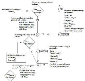
3.2.1 Secure Tree Construction Algorithm
At the beginning, all sensors are powered on with the “UNDECIDE" state. This means that the nodes are not yet in a constructed tree, and should start the operation of secure tree construction. Sensor nodes will change their state based on messages received from neighbor nodes. Initially the list of children of each sensor node is empty. The tree is constructed starting from base station.
Actions taken by Base station (BS): BS broadcasts an <Invitation> message; asking sensors to join the tree. BS then listens for incoming messages while waiting until predefined Timejoin-receive.
BS will treat <Join> messages and timeout event. On receiving a <Join> message from sensor node i, BS adds sender of the <Join> message (i.e., sensor node i) in its children list. On timeout event, BS broadcasts a <children-list> message.
Actions taken by sensor nodes: A sensor node i can be in one of two states: “UNDECIDE", or “ON". Sensor nodes will treat some particular types of messages and will ignore other types of messages depending on their state.
Sensor node with “UNDECIDE" state: Any sensor node i with “UNDECIDE" state that hears an <Invitation> message assigns its own level to be the level in the received <Invitation> message plus one, sets the sender of the <Invitation> message as its parent, changes its state to “ON", and computes the pairwise key with sender of the <Invitation> message. After that, sensor node i sends a <Join> message to its parent, broadcasts an <Invitation> message, and starts the timeout event.
Sensor node with “ON" state: Sensor node i with “ON" state listen for incoming messages while waiting until a predefined Timejoin-receive to receive the
join message. Sensor node i will treat <Childrenlist> message, <Join> messages and timeout event. On receiving a <children-list> message from its parent, sensor node i will maintain its list of siblings in its transmission range, and compute pairwise keys with siblings. On receiving a <Join> message, sensor node i adds sender of the <Join> message in its children list and computes the pairwise key with sender of the <Join> message. On timeout event, sensor node i broadcasts a <children-list> message.
Figure 1 shows the state flow chart (pseudo code) of secure tree construction scheme.
3.2.2 Tree-Reconstruction Scheme
In the previous sub-section, we have described how to construct a secure tree. We consider a WSN configured in tree structure that performs network tasks (i.e., sensing, aggregation, and data communi-
Fig. 1 Secure Tree Construction
cation). During network tasks, if a node receives a <childrenlist> message from its parent, it will update its list of siblings (i.e., add those siblings in the list which are in the node's transmission range), and compute pairwise key with new siblings. Sensor nodes are prone to failure due to lack of energy during network tasks. A sensor node failure (except leaf nodes) will disconnect the tree. The goal of our tree-reconstruction scheme is to maintain connectivity until too many nodes have drained out power and there are not enough nodes left to maintain connectivity. This depends on the node density. Our tree-reconstruction scheme focuses on sensor replacement upon sensor failure. All sensor nodes have a predefined time (i.e., Timereport-receive).
Timereport-receive express the amount of time assigned
for nodes to receive Report messages during tree-reconstruction phase. During network tasks, if a node's energy is lower than a pre-determined threshold, the node broadcasts an <alarm> message to inform its parent, children, and siblings that it will go down. Upon receiving an <alarm> message, a node will check its relation with sender of <alarm> message (i.e. failed node). There are three possible cases: failed node is parent, failed node is child, and failed node is sibling. A receiver node of <alarm> message not related to the failed node simply ignores the <alarm> message. Receiver node related to the failed node performs the following operations depending on the relationship with the failed node.
Case (1) failed node is parent: Failed node's children set their parent node equal to NULL, start the timeout event, broadcasts a <RequestParent> message, and waits for Report message until a predefined Timereport-receive. Their neighbors whose
parent is not equal to NULL (except siblings and children), after receiving the <RequestParent> message, send a <Report> message to the sender of the <RequestParent> message. On receiving first <Report> message, failed node’s children set their parent equal to sender of the <Report> message, compute pairwise key with the new parent, and respond with an <AckReport> message. On receiving an <AckReport> message, parent node adds the sender of <AckReport> message in its children list and computes pairwise key and broadcasts a <children-list> message. In the worst case scenario, when a failed node's child does not receive any <Report> message within the assigned time interval (i.e., Timereport-receive), it broadcasts an <alarm> message
and goes down.
Case (2) failed node is child: Failed node's parent removes the failed node from its children list, and broadcasts <children-list> message.
Case (3) failed node is sibling: Failed node's sibling removes the failed node from its siblings list, and decrements the number of siblings.
Figure 2 illustrates the pseudo code in the form of state flow chart of tree reconstruction scheme.
Fig. 2 Secure Tree-reconstruction
3.3 Privacy Preserving Data Aggregation Our scheme for privacy preserving Data aggregation comprises three steps: data slicing, data mixing and aggregation.
3.3.1 Data Slicing
In this step, we have improved the “slicing and mixing" step from [12] and [13]. In [12], [13], each node implement “slicing and mixing" with randomly selected J nodes within h hope. While in our scheme; each node implement “slicing and mixing" with siblings in the node's transmission range. Each node maintains list of siblings (Siblingsi) in its
transmission range during the tree construction phase. Let, Mi represents the number of siblings of node i (i
= 1 ... N) in its transmission range, and J is the upper bound for the number of slices into which each node divide its private data. We denote the private data sensed at node i (i = 1 ... N) by d(i), and a piece of data sent from node i to node j by dij . Hence, d(i) =
. dij
N 1 j
Note dii is kept locally at node i, no
transmission is needed for dii. For nodes to which
node i does not send any piece of data, dij=0. The
desired aggregated result, f, can be expressed as
dij fiN1NJ1
If Mi< J, then the node i slices its original
sensed data into Mi+1 pieces. After data slicing, node
i keeps one piece to itself, encrypts the remaining Mi
pieces using pairwise key with its siblings, and sends a piece to each of its sibling.
When Mi ≥ J, then the node i slices its original
sensed data into J pieces. Node i keeps one piece to itself, encrypts the remaining J-1 pieces using pairwise key with its siblings, and sends a piece to each of its sibling.
3.3.2 Data Mixing
On the reception of encrypted slice, node j decrypts the data slice with the key (shared between sender and receiver). After receiving the first data slice, it waits until predefined Timeslice-receive, which
guarantees that node received all slices sent by its siblings. Then, it combine all the received data slices,
, dij
3.3.3 Aggregation
On receiving all mixed data from its children, the node sends a message containing the aggregated result to its parent, which then forwards it to the base station through the routing tree. Eventually the aggregation reaches the base station.
4. Theoretical Analysis
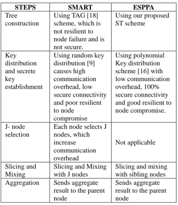
In this section, we compare original SMART and ESPPA schemes. Table 1 clearly state the difference between SMART and ESSPA.
Table 1 Comparison between SMART and ESPPA
STEPS SMART ESPPA
Tree construction
Using TAG [18] scheme, which is not resilient to node failure and is not secure.
Using our proposed ST scheme Key distribution and secrete key establishment
Using random key distribution [9] causes high communication overhead, low secure connectivity and poor resilient to node
compromise
Using polynomial Key distribution scheme [16] with low communication overhead, 100% secure connectivity and good resilient to node compromise. J- node
selection
Each node selects J nodes, which increase communication overhead Not applicable Slicing and Mixing
Slicing and Mixing with J nodes
Slicing and mixing with sibling nodes Aggregation Sends aggregate
result to the parent node
Sends aggregate result to the parent node
4.1 Communication Overhead
In SMART, each node needs 1 message for tree construction, 1+Ne(i) message (where Ne(i) is the neighbor nodes for node i) for secret key establishment, J+1 messages for J node selection,J-1 messages for slicing, 1 message for mixing, and 1 message for aggregation. Thus, each node needs 4+Ne(i)+2J. Thus, the total communication overhead in the network is 4NiN1Ne(i)2NJ.
In ESPPA, each node needs 3 messages for secure tree construction, M message for slicing,1 message for mixing and 1 message for data aggregation. Where, M is the number of siblings, it could be in between 1<M<=J.
Since in ESPPA scheme, if M>J then node will divide its data into J-1 pieces; so maximum messages transmitted by each node will be J-1. Therefore, the total communication overhead in the network is 4N+NJ.Which is much lesser than the SMART. 4.2 Security Analysis
In SMART, security requirement of data confidentiality is achieved partially by encrypting messages using pair-wise key during second phase i.e., privacy preserving data aggregation phase. Whereas, in ESPPA, security requirement of data confidentiality is achieved fully by encrypting messages using a common key K during 1st phase i.e, tree construction and using pair-wise key during second phase i.e., privacy preserving data aggregation phase.
SMART scheme achieves secure connectivity with probability P and poor resilience against node compromise due to random key distribution scheme [9].
ESPPA scheme achieves 100% secure connectivity and good resilience against node compromise by using an existing polynomial-based key distribution scheme proposed in [16]. The advantage of this scheme [16] is that any two sensors can definitely establish pairwise key. It is noteworthy that no information transfer is required to compute pairwise key. The scheme has good resilience against node compromise, which means that a node compromise does not affect the security of information communicated among non-compromised nodes.
SMART scheme has been implemented on top of TAG [18], which is not resilient to node failure. In TAG, a single node failure breaks sub-tree from the tree, thus sensor's reading from that sub-tree could not reach at the base station. It is important to maintain connectivity in WSNs after deployment in a monitored area. In this paper, we have presented a tree-reconstruction scheme to maintain the connectivity. Our tree-reconstruction scheme allows to exclude the failure nodes and reconstruction of the aggregation tree when a sensor node fails during network tasks.
We achieve data data privacy utilizing "slicing and assembling" technique with siblings. In ESPPA,
each sensor node encrypt slices using distinct pairwise key with its sibling and encrypt mixed data using distinct pairwise key shared with its parent. Therefore, it is difficult to break security of links between nodes in ESPPA scheme. In this condition, external adversaries, internal adversaries, and trusted neighbors cannot collect all the dataslices for a node.
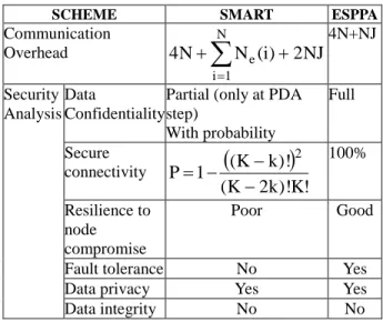
Table 2 gives theoretical analysis of both Original SMART and proposed ESPPA scheme. The simulation results are discussed in next section. Table 2 Theoretical analysis between SMART and
ESPPA
SCHEME SMART ESPPA
Communication
Overhead
N
1 i
e(i) 2NJ
N N 4
4N+NJ
Security Analysis
Data
Confidentiality
Partial (only at PDA step)
With probability
Full
Secure
connectivity
! K )! k 2 K (
)! k K ( 1 P
2
100%
Resilience to node compromise
Poor Good
Fault tolerance No Yes
Data privacy Yes Yes
Data integrity No No
5. Simulation Results
The parameters Timetree-phase, Timejoin-receive, and
Timeslice-receive required for our scheme are evaluated
via simulation in this section. This section also evaluates performances of our proposed ESPPA scheme in terms of communication overhead, privacy preservation, and energy consumption. WSNet simulator [1] is used as a simulation platform. We ran our proposed scheme on randomly generated sensor networks wherein N sensor nodes are deployed randomly in an area of 100 m × 100 m. The number of sensors N varies from 50 to 400. All sensor nodes have the same sensing range and transmission range of 15 m. All the simulations were run 50 times, and the average results are plotted in the graphs.
5.1 The Parameters Timetree-phase, Time join-receive, and Timeslice-receive
Timetree-phase should be large enough to ensure
that all messages transmitted during tree construction
phase have been reached at their destination and all nodes have joined the tree. During tree construction phase, each node has to wait for certain time (i.e., Timejoin-receive) to receive all join messages sent to the
node. These time parameters vary with the number of nodes deployed in the network. Due to unreliability of wireless communication and collision, number of messages may be lost during transmission. Therefore, we evaluate the time based on the maximum number of received messages.
First, for the evaluation of Timejoin-receive, we set
a large enough time to complete tree construction phase (i.e., Timetree-phase = 300 seconds). We note the
time to receive maximum number of join messages for different number of nodes deployed in the network. Then, using the observed Timejoin-receive, we
evaluate Timetree-phase. This time is evaluated based on
the maximum number of received messages (i.e., invitation and join messages transmitted during tree construction phase). The average time to receive maximum numbers of join messages and to complete tree construction phase is plotted in the Figure 3.
Figure 3 illustrates the effect of the number of nodes on time for receiving join messages during tree construction and time to complete tree construction phase. Results show similar trend and the time required increases non linearly with the increase in number of nodes for both the parameters of study.
Fig. 3 The parameter Timejoin-receive and Timetree-phase
During “slicing and mixing" step, each node has to wait for certain time, which guarantees that all slices sent to the node are received. In “slicing and mixing" step, the number slice messages transmitted varies with the value of J. Therefore, we evaluates the time for different values of J by varying number of nodes deployed in the network. This time is evaluated as the time to receive maximum number of
slice messages. The average time to receive maximum numbers of slice messages is plotted in the Figure 4.
Fig. 4 The parameter Timeslice-receive
Figure 4 presents the effect of factor J on the receiving time with respect the deployed node. These result depicts that the receiving time is directly dependent on J and number of node has insignificant effect. With the increase in J the time to receive slice messages has increasing value and for the same value of J the time to receive slice messages is almost same for all conditions of deployed nodes.
5.2 Communication Cost
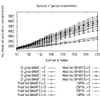
The number of messages transmitted in the network is used to evaluate communication overhead. We compare our proposed ESPPA scheme with three schemes: Original-SMART, Modified-MART2, and Modified-SMART3.
In the Original-SMART, a random key distribution scheme proposed in [9] is used for pairwise key establishment, an aggregation tree is constructed using an existing tree construction protocol known as Tiny Aggregation (TAG) [18], J-nodes are selected randomly within h hops by each node, and “slicing and mixing" is implemented with randomly selected J-nodes.
For better observation, we have modified original-SMART by using polynomial key distribution scheme and our proposed tree construction (ST) algorithm.
In Modified-SMART2, we use polynomial key distribution scheme for pairwise key establishment and the remaining steps including aggregation tree construction, J-node selection, “slicing and mixing" with selected J nodes and aggregation are same as in
the Original-SMART. In Modified-SMART3, aggregation tree is constructed using our proposed tree construction (ST) scheme, and the polynomial key distribution scheme is used for pairwise key establishment. The remaining steps including: J-node selection, “slicing and mixing" with selected J nods and aggregation are same as in the Original-SMART.
Figure 5 gives the communication overhead of ESPPA, Original-SMART, Modified-SMART2, Modified-SMART3 schemes with different values of J.
Fig. 5 Communication overhead with varying J values
It was concluded from the simulation results in Figure 5 that ESPPA scheme transmits less messages than the Original-SMART, Modified-SMART2, and Modified-SMART3 schemes. As is illustrated in Figure 3, Modified-SMART3 scheme has more communication overhead than the Modified-SMART2. This is because; TAG scheme has less communication overhead than the STscheme. In TAG, each node sends one message (i.e., invitation message), while in ST scheme, each node sends three messages (i.e., invitation, join, and children-list messages). Also, it has been observed from Figure 5, that the decrease of communication overhead of ESPPA scheme compared to Original-SMART, Modified SMART2, and Modified-SMART3 increase with increase in the value of J and increase in number of nodes deployed in the network.
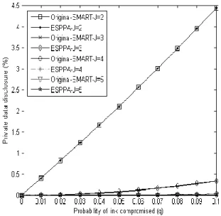
5.3 Privacy Preservation
There are two reasons that cause the privacy violation, that is, overhearing and colluding, as defined in [12]. We assume q as the probability that an attacker breaks the security of a given link. The capacity of privacy-preservation is represented by the probability P(q), which is the probability that private data is disclosed to someone else under a given q. Following the work in [12], P(q) can be approximated by
k d
k J
q
k
ree
in
P
q
q
P
(
)
max(
deg
)
0
1
Where, dmax is the maximum in-degree in a
network. P(in-degree = k) is the probability that the in-degree of a node is k.
During the evaluation of privacy preservation, we used the probability equation Poverhear = Pcollude = q for simplicity. In this section, we compare privacy preservation performance of ESPPA and Original-SMART for different number of deployed nodes in the network.
Figure 6 evaluates privacypreservation performance of ESPPA by comparing Original-SMART for different values of J, where we use a 100 node network. A node has an average degree of 8.
Fig. 6 Privacy preservation comparison for ESPPA and Original-SMART when nodes = 100 From Figure 6, it is difficult to analyze the results for both schemes when J = 3,4, and 5. For
etter observation, Figure 7 is a zoomed view of the lower portion of Figure 6.
Fig. 7 Zoomed view of Figure 4- Privacy preservation comparison for ESPPA and Original-SMART for when nodes = 100 Figure 8 shows privacy preservation performance of ESPPA and compare it with Original-SMART for different values of J, where we use a 200 node random network. The node has an average degree of 10. Figure 9 is a zoomed view of the lower portion of Figure 8.
Fig. 8 Privacy preservation comparison for ESPPA and Original-SMART when nodes = 200
Fig.9 Zoomed view of Figure 5- Privacy preservation comparison for ESPPA and Original-SMART when nodes = 200
Figure 10 evaluates privacy preservation performance of ESPPA and compares it with Original-SMART for different values of J, where we use a 400 node random network. The node has an average degree of 12. Figure 11 is a zoomed view of the lower portion of Figure 10.
Fig. 10 Privacy preservation comparison for ESPPA and Original-SMART when nodes = 400 It was concluded from the simulations above (i.e., Figure 4, Figure 5, and Figure 6) that privacy preservation capacity P(q) increase as J grows. Figure 4, Figure 5, and Figure 6, imply that privacy preservation capacity of ESPPA is approximately same as original SMART. In SMART, keys are taken
Fig. 11 Zoomed view of Figure 6- Privacy preservation comparison for ESPPA and Original-SMART when nodes = 400
from a large pool of keys randomly. Hence, same keys can be used by more than one node for secure communication. This helps adversaries to compromise at least some of the message communication, if it has same pair of keys. However, in ESPPA, each node has a distinct key with other nodes; there is slighter probability that private data is interrupted by eavesdropper during the message transmission. Therefore, the links between the neighbors in ESPPA approach are more difficult to break, and adversaries have less chance to collect all data slices for one node.
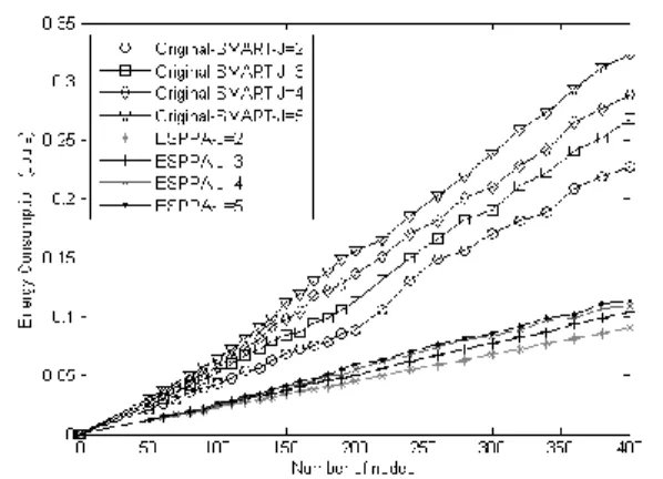
5.4 Energy Consumption
In our simulations, the energy expenditure of a node is calculated using the model proposed in [14]. In the model, energy expenditure to run the transmitter or receiver circuitry is Eelec = 50 nJ/bit and for the transmit amplifier is εamp = 100 pJ/bit/m2. Fig.12 below illustrates the energy dissipation model.
The energy consumed to transmit a k-bit message over a distance d is:
ETX (k,d)= Eelec k + εamp k d 2
And to receive this message, the consumed energy is:
ERX (k)= Eelec k
Figure 13 illustrates the comparison of energy expenditure for ESPPA, and original-SMART.
Fig. 13 Energy expenditure comparison for ESPPA, and original-SMART with varying J values It is concluded from the simulations (Figure 13) that our presented ESPPA scheme consumed less energy compared to the original SMART scheme. This is because high communication overhead in SMART scheme.
6. Conclusions and Future Work
In the paper, we have presented an approach to aggregate data in an energy efficient manner while preserve data security and privacy in WSNs. Our presented approach is based on an existing scheme, called SMART scheme. The objective of our approach is to minimize communication overhead and energy expenditure by optimizing some parameters. From this point of view, our proposed ESPPA scheme optimizes “slicing and mixing" step by implementing it with siblings in the node's transmission range instead of randomly selected J node within h hops. We have compared ESPPA scheme with SMART scheme and modified SMART schemes. Simulation results show that the ESPPA scheme significantly reduces communication overhead and saves energy than the SMART and modified SMART schemes. In the paper, we also present a tree-reconstruction
scheme to achieve network connectivity during data aggregation. However, in this work we have not analyzed tree reconstruction scheme. This is included in future work. Also, we plan to analyze the effect of maximum children to balance the network in secure tree construction (ST) scheme, and analyze privacy level at each individual node by introducing minimum and maximum number of siblings. In future work, we will prove the efficiency of our scheme in a real application via implementing our approach to real WSN.
References
[1] Wsnet simulator, available: http://wsnet.gforge.inria.fr/.
[2] K. Akkaya, M. Demirbas, and R.S. Aygun, (2008). “The impact of data aggregation on the performance of wireless sensor networks’’, Wireless Communications and Mobile Computing, 8(2): pp. 171-193.
[3] V. Bhoopathy and RMS Parvathi, (2011). “Energy efficient secure data aggregation protocol for wireless sensor networks’’, European Journal of Scientific Research, 50(1): pp. 48-58.
[4] R. Bista and J.W. Chang, (2010). “Privacy-preserving data aggregation protocols for wireless sensor Networks: A survey”, Sensors, 10(5): pp. 4577-4601.
[5] N. Brinis, L. Azouz Saidane, and P.Minet. “Edgm: (2012). Energy-efficient data gathering with data mules in wireless sensor networks”, 6th International Conference on Sensor Technologies and Applications, pages: pp. 277-283.
[6] H. C_am, S. Ozdemir, P. Nair, D. Muthuavinashiappan, and H. Ozgur Sanli, (2006). “Energy-efficient secure pattern based data aggregation for wireless sensor networks”, Computer Communications, 29(4):pp. 446-455. [7] S.A. Ch, M.M. Omair, I.A. Khan, and T.A.
Malik. (2011). “Ensuring reliability and freshness for data aggregation in wireless sensor networks”, International Journal of Machine Learning and Computing, pages pp. 224-230.
[8] S.Chatterjea and P.Havinga, (2003). “A dynamic data aggregation scheme for wireless sensor networks”.
[9] L. Eschenauer and V.D. Gligor, (2002). “A key management scheme for distributed sensor networks”, In Proceedings of the 9th ACM conference on Computer and communications security, pages 41-47, ACM.
[10] E. Fasolo, M. Rossi, J. Widmer, and M. Zorzi, (2007). “In-network aggregation techniques for wireless sensor networks: a survey”, Wireless Communications, IEEE, 14(2):pp. 70-87. [11] P.S. Fulare and N. Chavhan, “False data
detection in wireless sensor network with secure communication”, 2011.
[12] W. He, X. Liu, H. Nguyen, K. Nahrstedt, and TT Abdelzaher, “Pda: Privacy-preserving data aggregation in wireless sensor networks”, In 26thInternational Conference on Computer Communications, IEEE, pages 2045-2053, 2007.
[13] W. He, H. Nguyen, X. Liuy, K. Nahrstedt, and T. Abdelzaher, “ipda: An integrity-protecting private data aggregation scheme for wireless sensor networks”, In Military Communications Conference, pages 1-7, IEEE, 2008.
[14] W.R. Heinzelman, A.Chandrakasan, and H. Balakrishnan, (2000). “Energy-efficient communication protocol for wireless microsensor networks”, In Proceedings of the 33rdAnnual Hawaii International Conference on, pages 10 pp. IEEE.
[15] J. Hill, R. Szewczyk, A. Woo, S. Hollar, D. Culler, and K. Pister, (2000). “System architecture directions for networked sensors”, ACM Sigplan Notices, 35(11): pp.93-104. [16] H.F. Huang, (2008). “A pairwise key
pre-distribution scheme for wireless sensor network”, intelligence and Security Informatics, pages pp. 77-82.
[17] N. Li, N. Zhang, S.K. Das, and B. Thuraisingham, (2009). “Privacy preservation in wireless sensor networks: A state-of-the-art
survey”, Ad Hoc Net-works, 7(8):pp. 1501-1514, 2009.
[18] S. Madden, M.J. Franklin, J.M. Hellerstein, and W. Hong, (2002). “Tag: A tiny aggregation service for adhoc sensor networks”, ACM SIGOPS Operating Systems Review, 36(SI): pp. 131-146.
[19] A. Mahimkar and T.S. Rappaport, “Securedav: (2004). A secure data aggregation and verification protocol for sensor networks. In Global Telecommunications Conference, pages pp. 2175-2179, IEEE.
[20] I. Memon, (2012). “An analysis of privacy preserving data aggregation protocols for wsns”, Network and Parallel Computing, 7513: pp.119-128.
[21] H.O. Sanli, S. Ozdemir, and H. Cam, (2004). “Srda: secure reference-based data aggregation protocol for wireless sensor networks”, In Vehicular Technology Conference, pp. 4650-4654, IEEE.
[22] J. Sen, (2010). “A survey on wireless sensor network security”, arXiv preprint arXiv: 1011.1529.
[23] H.O. Tan and I. K.orpeog.lu. (2003). “Power efficient data gathering and aggregation in wireless sensor networks”, ACM SIGMOD Record, 32(4): pp. 66-71.
[24] Y. Yang, X. Wang, S. Zhu, and G. Cao, (2006). “Sdap: A secure hop-by-hop data aggregation protocol for sensor networks”, ACM Transactions on Information and System Security (TISSEC), 11(4): pp.18.
[25] Ramesh Karri , Piyush Mishra, (2002). Minimizing Energy Consumption of Secure Wireless Session With Qos Constraints", in Proc. Int. Conf. Communications.
[26] Li HJ, Lin K, Li KQ. Energy-efficient and high-accuracy secure data aggregation in wireless sensor networks. Computer Communications 2011; 34(4): pp. 591–597.
[27] C. Li and Y. Liu, " ESMART: Energy Efficient Slice-Mix-Aggregate for Wireless Sensor Network", International journal of Distributed
Sensor Networks, 2013.
[28] G. Yang et al, (2013). "Precision-Enhanced and Encryption-Mixed Privacy-Preserving Data Aggregation in Wireless Sensor Networks", International journal of Distributed Sensor Networks.
[29] Q. Wang, M. Hempstead, and W. Yang, (2006). "A Realistic Power Consumption Model for Wireless Sensor Network Devices", SECON. [30] C. B. Margi, K. Obraczka, "Instrumenting
network simulators for evaluationg energy consumption in power-aware ad-hoc network protocols, MASCOT04".
[31] I. Howitt, R. Neto, J. Wang, and J. M.Cornard, "Extend Energy Model for the Low Rate WPAN", MASS'05.
Dr. Irfana Memon pursued PhD degree specialized in “energy efficient secure and privacy data collection and data aggregation in wireless sensor networks” in Computers systems from Aix-Marseille Université, France. I received Master Research (Master recherche Informatique) degree in telecommunications network and services from INSA (Institute National des Sciences Appliquées), Lyon, France in 2009. I have done Bachelor of Engineering (B.E) in Computer Systems engineering (CSE) from Quaid-e-Awam University of Engineering, Sciences and Technology, Nawabshah, Sindh, Pakistan. I am actively engaged in graduate and undergraduate teaching and research with special interest in Wireless and Mobile communication, Data structures and algorithm, data base management, C++ programming language, Wireless sensor networks simulators.