Backlash Nonlinearity Modeling and
Adaptive Controller Design for an
Electromechanical Power Transmission System
R. Kalantari
1;and M. Saadat Foomani
2Abstract. Nonlinearity characteristics, such as backlash, in various mechanisms, limit the perfor-mance of feedback systems by causing delays, undesired oscillations and inaccuracy. Backlash inuence analysis and modeling is necessary to design a precision controller for this nonlinearity. Backlash between meshing gears in an electromechanical system is modeled by the use of dierential equations and a nonlinear spring-damper. According to this model, the paper shows that oscillations and delays cannot be compensated by a state feedback controller. Therefore, an adaptive algorithm is designed, based on dierent regions of the system angular position error. Since this controller needs an estimation of the backlash value, it is estimated by a learning unit in the adaptive controller. Simulations show that the presented adaptive controller can eliminate backlash oscillations properly, in accordance with previous works.
Keywords: Backlash nonlinearity; Backlash estimation and compensation; Adaptive controller.
INTRODUCTION
Many physical components of control systems have nonlinear characteristics, such as deadzone, hysteresis and backlash. The dierence between tooth space and tooth width in mechanical systems, which is essential for rapid working gear transmissions, is known as backlash. Complete omission of backlash results in an interference between the teeth. When the backlash is traversed, no torque is transmitted through the shaft and when the contact is achieved, the resulted impact can destroy the gears and cause a high frequency noise. The fast change between a zero and large torque makes the system dicult to control and undesired oscillations may remain in steady state response. In fact, there are many applications, such as dierential gear trains and servomechanisms that require the complete elimination of backlash inuences, in order to have a proper function.
In order to design a controller for backlash
1. Department of Electrical and Computer Engineering, Semnan University, Semnan, Iran.
2. School of Mechanical Engineering, Sharif University of Tech-nology, Tehran, P.O. Box 11155-9567, Iran.
*. Corresponding author. E-mail: r [email protected] Received 17 June 2008; received in revised form 29 April 2009; accepted 1 September 2009
compensation, the nonlinearities should be modeled precisely. A deadzone model and a describing function of backlash were presented by Slotine [1]. When there is backlash between the mating gears, the initial contact can be modeled as an impact phenomenon. Sarkar et al. [2] simulated backlash as a microscopic impact and showed that its presence can be detected and possibly measured using only simple sensors. Nordin et al. [3] presented a physical model of backlash; valid also for shafts with damping. This model was used in the evaluation of power train controls by Lagerberg and Egardt [4,5].
Backlash has a destabilizing eect on the con-troller, once the gears become part of a closed-loop control system. A number of approaches to control systems with backlash were reported in the litera-ture [6,7]. The reported approaches can be divided into three main categories: linear controllers, passive and active nonlinear controllers. By considering the plan studied by Boneh and Yaniv [8], a QFT controller is designed. This controller leads to a limit cycle in the system step response. To reduce the limit cycle amplitude, a switched controller is then designed. A new linear controller has been proposed by Mohan [9] to compensate backlash in a position control system with elasticity.
model-ing the dynamic behavior of a gear train with backlash nonlinearity, in addition to designing an adaptive con-troller for an electromechanical system. The simplicity and applicability of the method make it a useful tool to be applied in servo systems.
ELECTROMECHANICAL SYSTEM MODEL The electromechanical system considered in this paper consists of a pair of spur gears with backlash and a DC servomotor. Figure 1 shows a schematic view of this system.
The reaction force between gears produces the torque, 1. Neglecting the backlash, the model of gears
can be described by Equations 1 and 2:
1= Jlnl+ Bln _l ln; (1)
m Jmm Bm_m= 1; (2)
eliminating F results in:
m (Jm+ n2Jl)m (Bm+ n2Bl) _m+ nl= 0;
(3) or:
Jel+ Be_l nm l= 0; (4)
where n is gear ratio, m and l are the applied
torque of the motor and load and J; B and represent the moment of inertia, viscous friction coecient and angular position of two gears, respectively. Je and Be
are the eective moment of inertia and viscous friction in the output, respectively, and can be determined, as the following equations show:
Je= Jl+Jnm2; (5)
Be= Bl+Bnm2 : (6)
Figure 1. Electromechanical model.
A DC motor is used as an actuator in this system. Equations 7 and 8 form the electrical and mechanical parts of a DC motor model:
di dt =
1 L
Ri + V Kmddt
; (7) d! dt = 1 J
Kmi m Bddt
: (8)
The output torque generated by this actuator is min
Figure 1.
Equations 4, 7 and 8 can be arranged in a state space form as in the following equation:
2 4__!l
_i 3 5 = 2 6 6 6 6 4
0 1 0 0 Be
Je
km
nJe
0 Km
nL LR
3 7 7 7 7 5 2 4! i 3 5 + 2 40 00 1
J 1 L 0
3 5V
m
: (9)
This model can be used for designing a state feedback controller with optimum coecients. The backlash eect can be described by changing F in Equations 1 and 2.
CONTACT MODEL
The most serious problem in backlash modeling is the contact of teeth, when the gear driven becomes the driver and vice-versa. The reaction force in this phenomenon has been modeled in dierent ways in literature. In this paper, the gear-teeth reaction force, Fcnt, is composed of two nonlinear components: the
elastic force, Fk, and the damping force, Fc. Contact
will occur when gears traverse the backlash space as Equation 10 shows:
jdxj = jR1m R2lj d=2: (10)
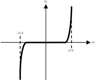
Initially, the rst gear is placed in the center of the empty space between two teeth of the second gear at the starting point. The left hand side of Equation 10 expresses the dierence between the linear distances of the two gears from starting point dx. The value of the nonlinear elastic force depends on the relative position of the gears and is shown in Figure 2.
A proper equation for Figure 2 can be described in Equation 11:
Fk =
dx d=2
n
; (11)
where n is a big odd number and simulates the rate of increasing in Fcnt. is the elastic coecient and
describes its value. Oscillation elimination in the numerical solutions of this nonlinear equation needs a
Figure 2. Nonlinear elastic force.
viscous force. It has been determined, according to Equation 12 below:
Fc= dv
dx d=2
n+1
; (12)
where is a constant factor and dv is the dierence between the two gears linear velocities. Therefore:
Fcnt=Fk+Fc=
dx d=2
n
+dv
dx d=2
n+1
: (13) From Equations 1, 2, 7, 8 and 13, a complete nonlinear model can be developed for the system.
CONTROLLERS
Two control approaches have been employed in this study. First, it has been shown that a linear state feed-back controller can just eliminate the big error in the respective system. Therefore, an adaptive nonlinear controller including two state feedback sub-controllers was presented to compensate for the undesirable eects of the backlash.
A state-feedback regulator is designed to minimize the quadratic cost function of Equation 14:
J =
1
Z
0
[Q11( d)2+ Q22!2+ 2]dt: (14)
According to Equation 9, the angular position and velocity of the output gear and the electrical current of the motor are chosen as state variables. Load torque, l, is considered as disturbance. By the calculation of
DC steady state inputs of the system, the input will be described in the following equation:
V = kL k1( d) k2! k3i; (15)
where the disturbance gain is k = n
R+k3
km
. Figure 3 shows a block diagram of this linear con-troller.
The eect of backlash nonlinearity appears in the steady state response to the step input, as periodic os-cillations (Figure 4). The amplitude of these undesired oscillations depends on the backlash value.
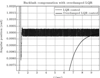
The rst proposed manner to compensate these oscillations is an over damped controller, but this causes an output with a big rising time. The com-prising of outputs can be observed in Figure 5.
By considering these results, an adaptive nonlin-ear controller is designed as a backlash compensator. Based on the amount of output error, this controller is divided into two regions of operation: region of big error and region of small error.
In the rst region, a fast state feedback regulator eliminates the big error. To compensate the gear oscillations in the second region, an over damped state feedback regulator is used. A switch chooses the required controller by means of estimated backlash space.
A learning unit is designed for the estimation of
Figure 3. Block diagram of state feedback controller with disturbance input.
Figure 5. System with state feedback and over damped controller.
backlash space. This unit computes the amplitude of oscillations, based on the system response to a very fast controller. Figure 4 shows the system's steady state oscillations. The amplitude of the remaining wave is very close to backlash space. Figure 6 shows the block diagram of the adaptive algorithm.
When the gears are near the desired value, back-lash causes fast changes between zero and large torque transmitting through the shaft. In this manner, over-damping the response of the system can reduce the changes satisfactorily as shown in simulations. A noteworthy feature of this controller is the valuation of d (backlash width), based on the system outputs, which causes more acceptable results than the other kinds of proposed controller [6,7].
SIMULATIONS
Simulation in Matlab of the dynamic behavior of spur gears with backlash helps us to predict its behavior. A sinusoidal input as motor torque and a constant input as load torque are assumed in the model. Figure 7
Figure 6. Block diagram of adaptive algorithm.
Figure 7. Output of electromechanical system by sinusoidal torque input. (a) Reaction force between gears; (b) Linear dierence of displacements; and (c) Linear dierence of velocities of two gears.
shows the changes of reaction force, linear distances and linear velocities dierence between gears.
The reaction force between gears, as illustrated in Figure 7a, has a big value at the contact time. In other cases, it changes sinusoidally, as an input torque. Figure 7b shows that linear distances of two gears change between d=2 and d=2. Linear relative velocity, as shown in Figure 7c, is zero except in the contacts in which it goes to a high value.
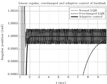
To evaluate the control strategies and compare them, the system has been simulated, according to the block diagram of Figure 8.
Results of the simulations for two linear controls and one nonlinear control are presented in Figure 9. A state feedback regulator has a good rising time, but it keeps oscillations in backlash space. Although these oscillations damp in an over damped regulator, the rising time is not acceptable. In comparison with them, the adaptive controller has good controlled characteristics. After switching occurs, gears have just one or two impacts and then the system will be properly stable.
COMPARISON
As mentioned before, a new linear controller has been proposed by Mohan [9] to compensate backlash in a position control system with elasticity. The step
Figure 8. Block diagram of the controlled electromechanical system.
Figure 9. Comparison of outputs in a high performance state feedback regulator, over damped state feedback regulator and adaptive controller.
response of the resulting system is shown in Figure 10. This graph shows the load position angle in radians versus the time in seconds. It is seen that the limit cycle is eliminated, but has some overshoot.
Comparison of the results from this controller and the presented adaptive controller (Figure 9) shows that, although the linear controller traverses the backlash slightly faster than the other one, the adaptive con-troller not only properly eliminates the limit cycle, but also has no overshoot in the output.
ROBUSTNESS
As a test of sensitivity to noise, a noise with amplitude of approximately 1% of the signal level is added to the measured angular position signal. Results for the systems with or without noise for the adaptive controller are shown in Figure 11.
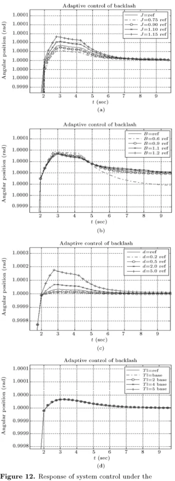
Moreover, the simulations have been performed for variations of internal parameters, such as moment of inertia, viscous friction coecient and backlash space. The load torque for the adaptive control can be seen in Figure 12.
Figure 10. Step response of Boneh-Yaniv system with backlash and the Mohan's linear controller [9].
Figure 12. Response of system control under the
variation of parameter. (a) Variation of moment of inertia; (b) Variation of viscous friction; (c) Variation of backlash space; and (d) Variation of load torque.
Figures 12a and 12b show that variations in moment of inertia and the viscous friction coecient in the considered range do not have noticeable eects on the controller operation; the adaptive controller is robust with changing the values of these parameters.
Increasing backlash space and keeping the radius of gears constant require more angular rotation from the gears to ll the backlash space in the backlash region. Figure 12c exhibits this eect when backlash space is 5 times bigger than the reference value.
Figure 12d shows the result of changing the load torque from 0.1 to 0.5 Nm. Increasing load torque while considering motor torque input can be a damping factor for second gear oscillations in the backlash region.
Simulation results from Figure 12 show the ro-bustness of the system to variations of inertia, viscous friction and backlash space.
CONCLUSION
Many hardware solutions have been developed to overcome backlash. These solutions can satisfactorily handle the backlash problem, but give rise to other problems, such as decreasing accuracy and reducing bandwidth. In this study, a software solution was proposed for the compensation of backlash.
An electromechanical system consisting of a pair of spur gear with backlash and a DC servomotor is modeled. As seen in simulations, the steady state response of this system, by means of a linear state feedback controller, has periodic oscillations around its desired value. A nonlinear adaptive controller has been designed for the system with two linear controllers in two regions of the operation. A learning unit estimates the backlash space for switching between controllers. A fast state feedback regulator for the region of contact and an overdamped one for the backlash region are proposed. By use of a position sensor, the feedback system can estimate backlash space and compensate for its undesirable inuences.
The simulations show that the adaptive system and estimation unit are quite insensitive to a high level of noise. Indeed, the system control can operate properly within a wide range of variations in internal parameter values and backlash space.
REFERENCES
1. Slotine, J.J.E. and Weiping, L., Applied Nonlinear Control, Prentice-Hall, Inc., Englewood Cli, New Jersey (1991).
2. Sarkar, N., Ellis, R.E. and Moore, T.N. \Backlash detection in geared mechanisms: Modeling, simulation and experimentation", Journal of Mechanical Systems and Signal Processing, 11(3), pp. 391-408 (1998).
3. Nordin, M. and Gutman, P.O. \Controlling mechanical systems with backlash - a survey", Automatica, 38(10), pp. 1633-1649 (2002).
4. Lagerberg, A. and Egardt, B. \Evaluation of control strategies for automotive powertrain with backlash", Presented at AVEC'2, Intl. Symo. On Advanced Ve-hicle Control 2002, September 9-13, Hiroshima, Japan (2002).
5. Lagerberg, A. and Egardt, B. \Backlash estimation with application to automotive powertrains", IEEE Transaction on Control Systems Technology, 15(3), pp. 483-493 (May 2007).
6. Nordin, M., Galic, J. and Gutman, P.O. \New models for backlash and gear play", International Journal of Adaptive Control and Signal Processing, 11, pp. 49-63 (1997).
7. Rostalski, P., Besselmann, T., Baric, M., Van Belzan, F. and Morari, M. \A hybrid approach to model-ing, control and state estimation of mechanical sys-tems with backlash", International Journal of Control, 80(11), pp. 1729-1740 (2007).
8. Boneh, R. and Yaniv, O. \Reduction of limit cycle amplitude in the presence of backlash", Journal of Dynamic Systems, Measurement and Control, Trans-action of the ASME, 12(2), pp. 278-284 (1999). 9. Mohan, M.A. \A new compensation technique for
backlash in position control system with elasticity", 39th Southeastern Symposium on System Theory, Mer-cer University, Macon, GA, 31207, March 4-6 (2007).