Sharif University of Technology
Scientia IranicaTransactions A: Civil Engineering www.scientiairanica.com
Research Note
Retrotting I-beam to double-I built-up column
connections using through plates and T-stieners
Gh. Ghodrati Amiri, M. Azimi
and E. Darvishan
Center of Excellence for Fundamental Studies in Structural Engineering, School of Civil Engineering, Iran University of Science & Technology, Tehran, Iran.
Received 20 September 2012; received in revised form 10 April 2013; accepted 13 August 2013 KEYWORDS
T-stiener; Double-I built-up section;
Through plate; Retrotting.
Abstract. Double-I built-up sections have been used extensively in Iran, according to previous versions of Iranian building codes. Despite recent developments in steel moment connections, based on studies for I-beam to H-shaped column connections, there are few documents available for I-beam to double-I built-up column connections. Recent studies have revealed that connections with double-I built-up columns exhibit dierent behavior compared to connections with H-shaped columns. Due to excessive out-of-plane deformations of the cover plate in non-retrotted moment connections, they have semi-rigid behavior. The objective of this study is to build on previous studies and to investigate strain distribution patterns and load transfer mechanisms in the retrotted I-beam to double-I built-up column connections using plates and T-stieners. In this paper, both horizontal and vertical elements of the T-stieners were modied and studied. Analytical models were designed and analyzed under cyclic and monotonic loadings. Three dierent indices were computed in the connection region in order to assess the local failure potential and the moment-rotation hysteretic curves were employed to evaluate the seismic performance of the connections. With the proposed congurations, strain is uniformly distributed within the critical elements. Moreover, excessive deformation of the column cover plate is eliminated.
c
2013 Sharif University of Technology. All rights reserved.
1. Introduction
Built-up sections are widely used as part of steel moment resisting frames in areas of high seismic risk in Iran. Double-I built-up columns usually consist of two IPE sections connected to each other by two cover plates. Numerous studies have been carried out on steel moment connections with H-shaped columns. Little research, however, has been carried out into the performance of moment connections with built-up
*. Corresponding author. Tel. +98 21 77240090 Fax: +98 21 77240398
E-mail-addresses: [email protected] (Gh. Ghodrati Amiri), azimi [email protected] (M. Azimi), [email protected] (E. Darvishan).
columns. Therefore, there are few documents available to evaluate these types of connection. In addition, connections with double-I built-up sections require dierent reinforcing details, which are not included in FEMA documents [1,2]. Therefore, the authors believe that these connections need further investigation to obtain the best feasible retrotting design for existing buildings.
The latest version of the Iranian Specications for Design and Construction of Steel Buildings [3] does not allow application of these connections in the new designed steel structures without reinforcement. Fur-thermore, it recommends using a vertical diaphragm plate inside the column that connects two cover plates in the connection region. Application of internal plates for retrotting purposes is a dicult and expensive
procedure. Hence, researchers try to nd new load transfer paths via external stieners [4]. Deylami et al. carried out analytical and experimental studies on I-beam to double-I built-up column connections [5-7]. Their results indicate that the best load transfer path from the beam to the column is through the side plates. Previously, Mazrooee et al. [8] had shown that out-of-plane loads on the column cover plate cause large deformations in non-retrotted I-beam to double-I built-up column connections, con-sequently, resulting in the semi-rigid behavior of the connection.
Other researchers have conducted a series of studies about load transfer mechanisms and failure modes of connections with box columns. Lee et al. [9-12] carried out analytical and experimental studies on moment connections with I-beams and box-columns. In their articles, they investigated the eects of the external stieners on the local and global behavior of the specimens, and concluded their study with a design guide for application of T-stieners in I-beam to box-column connections. Recently, Ghobadi et al. [13] introduced a new criterion for designing T-stieners. Their results show that the shear capacity of the horizontal element of a T-stiener depends on the aspect ratio of the element. In addition, the thickness of the element has no signicant eect on its shear strength. Furthermore, Kiamanesh et al. [14] investigated eects of dierent dimensional parameters on strain distribution patterns in these connections. In order to reach the greatest rigidity and strength, Goswami and Murty proposed an inclined rib-plated collar-plated conguration for moment connection with a box column. Their proposed connection provides pla-nar continuity between two webs in an I-beam to box-column connection which reduces stress concentration in the connection zone [4,15].
In this study, a common moment I-beam to double-I built-up column connectio5n is selected for retrotting purpose. Retrotting this type of con-nection is a challenging problem in existing buildings in Iran. The problems of insucient connection strength and stiness were resolved in the retrotted models by introducing internal diaphragm plates and T-stieners, as well as application of triangular plates. Both local and global behaviors of the connections were evaluated under cyclic and monotonic loadings. Results conrm that using internal through plates without application of the external stieners does not provide a reliable load transfer mechanism. In addition, the proposed congurations in this study introduce new load transfer paths, which are dierent from those used in the conventional connection de-sign. Moreover, with the proposed retrotting method, strain demand is uniformly distributed in the critical elements.
2. Evaluation of the non-retrotted connection Figure 1 shows four typical built-up sections used in Iran for bending and compressive members in steel frames. Section (A) is composed of two IPE Sections connected to each other by the distance marked in gure as a. Section (B) is similar to (A), but with another IPE section between the two other IPEs. These three sections are welded together by groove welds, and column cover plates connect the two exterior sections. Except for the friction, there is no other interaction between the column cover plate and the third IPE section. The other two sections in the gure are built with the same approach. All four sections share a common problem. The column cover plate does not have sucient out-of-plane stiness to resist the forces at the beam anges levels.
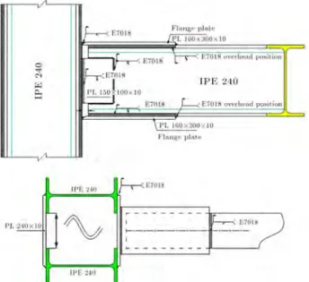
To study the behavior of the present connections, a common moment connection (model S-00 in Figure 2) was designed, based on the classic beam theory in previous versions of the Iranian Specications for Design and Construction of Steel Buildings. According to design concepts based on the classic beam theory for moment connections, the bending moment and shear force are transferred to the column cover plate by two beam cover plates and a shear tap, respectively. Figure 3 shows the load transfer mechanism according
Figure 1. Typical built-up sections used in Iranian construction projects.
Figure 2. Details of a common moment connection according to the previous building codes.
Figure 3. Load transfer mechanism and distribution of out-of-plane forces on the column cover plate.
Figure 4. Forces on connecting elements and cover plate deformation.
to the classic beam theory and the out-of-plane forces on the column cover plate.
Due to the small out-of-plane stiness of the column cover plate, the compressive and tensile forces at the beam ange levels impose excessive deformations on this critical member, causing it to have a semi-rigid behavior (Figure 4). These deformations overload the weld elements, which were not considered in the design criteria. Therefore, using classic beam theory does not provide us with a proper understanding of the behavior of the connection. The truss analogy theory, which has been introduced and developed in recent years, is more reliable and closer to reality [16].
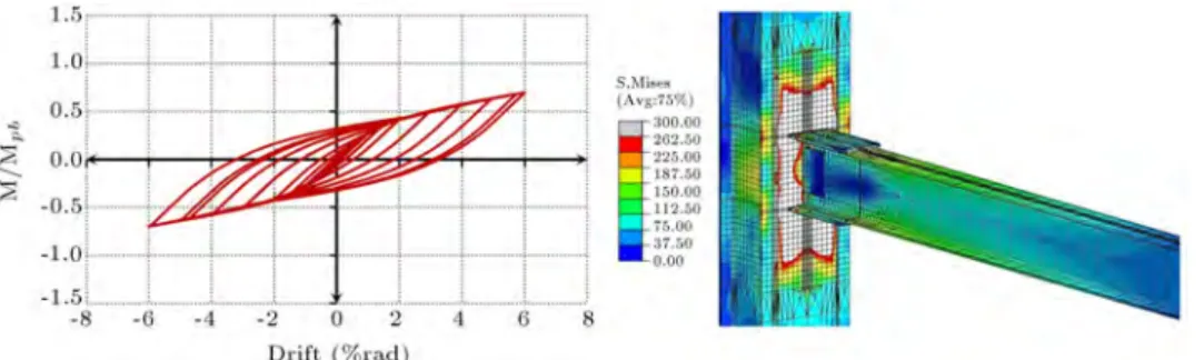
To resist the compressive force at the ange level, some engineers prefer to use another IPE section inside the column (Section B in Figure 1). However, the tensile ange still imposes large deformations on the column cover plate. Others try to nd new load transfer mechanisms using stieners. The hysteretic response and Mises stress distribution contours are shown in Figure 5 at the end of cyclic loading (6%
rad drift) for the non-retrotted connection. In this gure, M is the moment load at the column face and Mpb is the beam plastic moment. The drift angle
is dened as the vertical displacement of the beam tip divided by the beam length. The strength of a connection is determined by the maximum moment it is capable of carrying out. In a moment resisting frame, (a) the connection would be capable of sustaining an inter-story drift angle of at least 0.04 radians and (b) the moment strength of connection, determined at the column face, would be equal to at least 0.8 Mp of the connected beam at inter-story drift angles of 0.04 radians. The response of connection S-00 under cyclic loading implies that it needs reinforcing through the application of stieners. A large area of the connection zone is stressed beyond its yield point due to the small stiness of the column cover plate, and connecting elements undergo a high stress concentration because of poor prediction of the force ow path. In addition, the plastic hinge does not form in the beam. These defects in the present connections would cause premature failure during a real earthquake.
3. Finite element modeling
Nonlinear Finite Element (FE) analyses were employed to study the local and global behavior of the connec-tions. The general purpose nite element program ABAQUS [17] was used to model the three dimensional sub-assemblages of the beam-column connections. Dif-ferent element types were tried in order to nd suitable elements to simulate the behavior of the connections. The beam, column, and stieners were meshed and discretized by 8-node linear brick (C3D8R) and 4-node linear tetrahedral (C3D4) elements with reduced integration and hourglass control. Finer mesh was used to model the critical zones in the connection region. Transition of the coarser mesh (50 mm) to the ner mesh (10 mm) was modeled using 6-node linear solid wedge elements. Tetrahedral elements were also used in the complicated areas.
Due to symmetry in both geometry and loading, only half of the sub-assemblages were modeled. How-ever, the results are shown in complete 3D models to
Figure 6. Meshing details of the nite element models.
provide understandable gures. Meshing details of the models are depicted in Figure 6. Both geometric and material nonlinearities were considered in the analyses of the models. The material was dened based on a bilinear stress-strain curve. The rst part of the curve up to the proportional limit represents the elastic part. The plasticity model is based on the Mises yielding criterion and kinematic hardening ow rule. In all nite element analyses, the fundamental assumptions made to idealize steel mechanical properties are as follows: Young's modulus = 210 GPa, Poisson's ratio = 0.3, yield stress = 300 MPa and tangent modulus = Young's modulus/50. To simulate the boundary conditions of the column ends, a reference node is introduced as the master node at each end and the other nodes are constrained. Consequently, all the nodes behave as one rigid body. Therefore, DOFs are applied to the reference nodes, only. This method is also used to distribute the displacement load uniformly among the beam tip nodes. Using this method does not require further dening of any rigid parts at the end of the members.
Performance of the beam-to-column sub-assemblages under large reversed cyclic displacement loading provides an understanding of the probable inelastic behavior of the connections during strong ground motion. Thus, FEMA [1], multi-cycle displacement-controlled load history for connection prequalication was used for evaluation of seismic performance (Figure 7).
In a similar way, a monotonic displacement de-mand, up to a story drift angle of 4% rad, was imposed at the beam tip using displacement control loading. The corresponding history of the applied load was calculated from the reaction histories at the beam tip. The applied displacement to the reference point at the beam tip is dened as:
= Drift Lb; (1)
where = beam tip displacement; Lb=beam length.
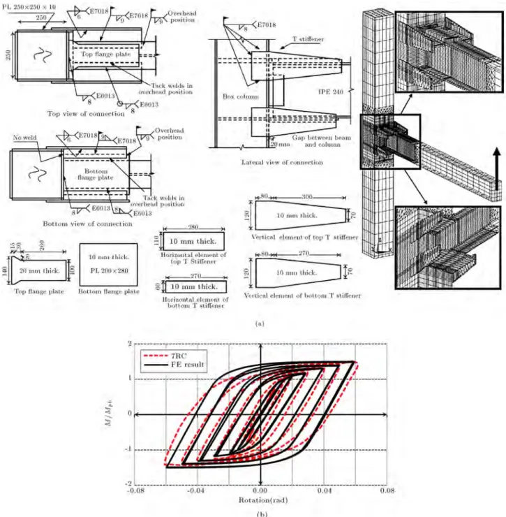
To compare and verify the validity of the analyt-ical models, the specimen RC7 in the study conducted by Ghobadi et al. [13] was simulated, as shown in Figure 8(a). The hysteretic curves obtained from the analysis and the report, are plotted in Figure 8(b).
4. Congurations of the retrotted connections
Unlike the similar geometry properties around both lo-cal axes in built-up box columns, thin webs in double-I built-up columns require dierent retrotting methods in each direction. This feature in double-I built-up columns also facilitates the reinforcing process from the inside of the column. The application of horizontal and vertical diaphragm plates, called Through Plates (TP) in this paper, was studied. Figure 9 shows the retrotted models using the horizontal (TPH) and vertical (TPV) plates installed inside the column. Two horizontal plates are connected to the column elements at the beam anges levels by CJP welds. Therefore, the continuity between the beam ange plates, column webs and anges provides a smooth path for transfer of the beam load to the column elements. In addition,
Figure 8. (a)Fabrication details. (b) Cyclic response of model RC7 and the FE result.
through plates signicantly eliminate the out-of-plane deformations of the column cover plate. All the stiener elements are considered to have the same thickness, equal to 10 mm in this study. Both of the connection congurations were modied using external rib plates, in-plane with TPs. These connections are shown as TPH M and TPV M in Figure 9. In model TPH M, the triangular plates are welded to the beam ange plate and the column ange. In order to ensure planar continuity, rectangular stieners are also welded between two column anges. Based on the studies on the ow of forces, retrotted models were designed
to provide a smooth path for transference of load with minimum strain concentration by T-stieners. These connections consist of the model S-00, T-stiener elements and external doubler plates. Retrotted models are approximately similar to each other, with some dierences in the stieners conguration in the connection zone. Therefore, they are categorized as three types: TS, TSH and TSF. In model TS, two pairs of T-stieners and external doubler plates were used. The horizontal elements of the stieners are connected to the beam anges and cover plate with groove and llet welds, respectively. Doubler plates
Figure 9. Details of the retrotted connections using through plates.
Figure 10. Connections stiened by T-stieners.
are welded to the column anges in-plane with the T-stieners anges. The thickness of the doubler plates is equal to the T-stiener ange, and its length is also selected based on the force ow pattern and the stress development through the T-stiener. In the model of type TSH. The horizontal elements were modied in order to keep the stress distribution before the critical welded area. Hence, according to Figure 10, the angle between the beam ange and the outer edge of the horizontal element, , was introduced with two values of =30 and =45 degrees.
In the model of type TSF, the tapered vertical elements of the T-stieners were also extended and
Table 1. Details of the connections reinforced by T-stieners.
Model Type LTS bVTS bHTS LDP
TS TS 300 { 150 80 800
TSH45 TSH 300 45 150 80 800
TSH30 TSH 300 30 150 80 800
TSF45L2 TSF 200 45 150 80 800
TSF30L2 TSF 200 30 150 80 800
TSF45L3 TSF 300 45 150 80 800
TSF30L3 TSF 300 30 150 80 800
welded to both the horizontal elements and the beam anges having the angle . Other geometric details of the nite element models are given in Table 1. The beam length and column height are 2500 and 3000 mm, respectively. Beams, columns and their details meet the requirements of AISC Specications for Structural Steel Buildings [18].
5. Evaluation of the global responses
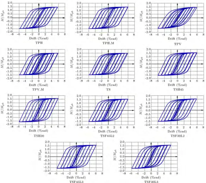
Eleven connections with dierent congurations were modeled according to the details given in the previous section. The performance of the connections under cyclic and monotonic loading is shown and discussed in the form of moment-rotation diagrams and strain dis-tribution contours. Cyclic responses of the connections are plotted in Figure 11 as the hysteretic loops. All the retrotted models show improved responses under cyclic loading.
In order to measure energy dissipation, the area of the hysteretic loops formed by the moment-rotation relationship of the connections was computed and dened as the energy that could be dissipated during cyclic loading. Figure 12 shows the dissipated energy in the last cycle of loading for all twelve connections. This quantity is almost constant for the models stiened by TPs. Comparison of the hysteretic loops reveals that the retrotted models with external stieners have sucient strength and energy dissipation. Model TSF45L3 dissipates 14 percent more energy comparing to model TS, which its stiener elements are not modied. Likewise, model TSH30 dissipates more energy compared to model TSH45, and both of the above-mentioned models dissipate more energy than the TS model. Thus, besides the local response, each modication method aects the global behavior of the connections as well.
Figure 13 shows normalized moment at the col-umn face versus drift angle for the analyzed models under monotonic loading. Each curve exhibits dierent characteristics of the connections. Connection S-00 has insucient strength and stiness. However, connection TSF is properly retrotted and has sucient strength and stiness to meet criteria requirements.
Connec-Figure 11. Cyclic responses of the connections, and normalized moment at column face versus drift angle.
Figure 12. Dissipated energy in the last cycle of loading and the strength of the connections.
tions TPV and TPH, with considerable strength, have smaller stiness.
6. Load transfer mechanism
Load transfer mechanisms in both retrotted and non-retrotted connections are quite dierent from those
used in the conventional connection designs. Based on analytical studies, it has been proven that the classic beam theory does not always provide a reliable load transfer path in the conventional connections [16]. In addition, it does not assure the formation of the plastic hinge in the beam, away from the column face. As depicted in Figure 14, in the retrotted connections
Figure 13. Monotonic normalized moment at column face versus drift angle of the connections.
Figure 14. Principal stresses directions in models TS and TSH30.
with T-stieners, the load transfer mechanism is sig-nicantly altered. This phenomenon can be clearly explained, according to the principal stress direction in connection elements. As a result, with the application of T-stieners in the retrotting process of a weak
Figure 15. Eect of the horizontal element of the T-stiener on stress distribution.
moment connection, the plastic hinge moment is devel-oped and transferred rst to the T-stieners and then to the column. Moreover, comparison of Figure 15(a) with Figure 15(b) shows that the modied horizontal element of the T-stiener eciently contributes to the uniform stress contribution in the critical zones by oering an eective path for force ow. Figure 15 shows the Mises stress contours for models TS and TSH30 at the end of cyclic loading. Formation of the plastic hinge is limited to the region behind the key elements in the modied conguration (TSH30).
7. Evaluation of the local responses
In the nite element analyses conducted in this arti-cle, cracks were not modeled explicitly. To compare local responses of the dierent model congurations analyzed in this research, three dierent indices were computed. This methodology and approach have also been used by other researchers to compare dierent congurations [13,19]. Two scalar quantities were employed to compute the indices of strain and stress at the critical points of the connections: Plastic equivalent strain (or PEEQ) and equivalent tensile stress (or Mises stress). The Mises stress is used to predict the yielding of materials under multi-axial loading conditions. It is dened as:
y =
r 3
2SijSji: (2) The plastic equivalent strain (PEEQ) represents the local inelastic strain demand and is dened as:
PEEQ = r
2
where, Sij and "ij are the components of the deviator
stress tensor and the plastic strain components, respec-tively. PEEQ index is dened as the PEEQ strain divided by the yield strain. To compare the potential for the ductile fracture of two congurations, the Rupture Index (RI) was computed at critical points. The rupture index is dened by the following relation:
RI = PEEQ (index) /exp( 1:5m
eff); (4)
where, mand eff are hydrostatic and Mises stresses,
respectively.
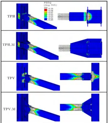
The application of the vertical through plate with triangular stieners is suggested as the best method for reinforcing the weak connection using TPs. The step-by-step fabrication process (by assembly sequence number) of the replaced elements is shown in Figure 16. Figure 17 shows the plastic equivalent strain contours for the retrotted connections using through plates. Comparing the two models, TPH and TPV, shows that using two horizontal plates as the internal diaphragms at the beam ange levels eectively resists the out-of-plane forces on the column cover plate, and also reduces strain concentration. Under the same circumstance, a modied form of model TPV with the vertical di-aphragm plate (TPV M) exhibits a better performance compared to the connection with the horizontal rib plates (TPH M).
Figure 18 shows PEEQ contours for the models retrotted with external T-stieners at the end of the full multi-cycle loading history (6% rad drift). Compar-ison of two models, TSH45 and TSH30, implies that a smaller (Figure 10) results in a more uniform strain distribution. Most connection elements in retrotted models, including the welds, remain elastic, even at the end of the full multi-cycle loading history. In the modied connections, the beam anges are expected
Figure 16. Retrotting details of the connections using vertical plate.
to undergo large plastic strain demands away from the column cover plate and, consequently, cause the formation of the plastic hinge.
To predict failure initiation, the over-stressed areas are investigated. The maximum stress and its
Figure 17. Plastic equivalent strain contours at the end of cyclic loading (6% rad drift).
Figure 18. Plastic equivalent strain contours at the end of cyclic loading (6% rad drift).
Table 2. The maximum stress and its location at 0.04 radian of drift angle.
Model Location of the maximum stress Max. stress
(MPa) S-00 Column cover plate weld at beam ange level 384.8 TPH Welds which connect TPs to column cover plate 379.3 TPH M Beam ange in vicinity of the triangular rib plates 350.9 TPV Welds which connect beam cover plates to column 386.0 TPV M Beam ange in vicinity of the triangular rib plates 403.5 TS Beam ange at the end of the T-stieners elements 366.8 TSH45 Beam ange, in location of expected plastic hinge 366.7 TSH30 Beam ange, in location of expected plastic hinge 368.5 TSF45L3 Beam ange, in location of expected plastic hinge 369.1 TSF30L3 Beam ange, in location of expected plastic hinge 387.4 TSF45L2 Beam ange, in location of expected plastic hinge 369.5 TSF30L2 Beam ange, in location of expected plastic hinge 446.9
Figure 19. Mises stress along the CJP weld at the end of cyclic loading.
location at 0.04 radian drift angle are given in Table 2. In S-00, the tensile force in the beam ange level imposes stress concentration in the column cover plate welds, although these areas are among critical elements and should not have any stress concentration. In the models with internal diaphragms, maximum stress occurs where the stieners connect to the beam ange and column. For the retrotted models, using T-stieners, the maximum stress occurs in the beam anges and at the location of the expected plastic hinge.
Observations after major earthquakes in the world have proven that welds are the most vulnerable ele-ments in moment connections. Figure 19 shows the Mises stress along the CJP weld, which connects the ange plate to the column.
In the non-retrotted connection, the stress level is high along the weld. Reinforcing the connection from inside the column, in models TPH and TPV, increases
stress concentration in this region. Therefore, for any methods of retrotting, using the external stieners is necessary. Application of the external triangular plates minimizes the stress level in the connection zone by distributing the load uniformly between the elements. Similarly, T-stieners reduce the stress level in CJP welds by introducing another load transfer mechanism via stieners and doubler plates.
The out of plane deformation history of the column cover plate versus time is plotted in Figure 20. It is obvious that the out of plane deformations of the column cover plate considerably decrease at the beam ange level and the column face in the retrotted models. Reduction of this quantity decreases risk of failure initiated in the groove welds between the beam and the column.
In connection S-00, local plastic strain demand is relatively high in the column welds at the beam anges level. These welds are considered critical elements in a
Figure 20. The out of plane deformation of the column cover plate at beam ange level.
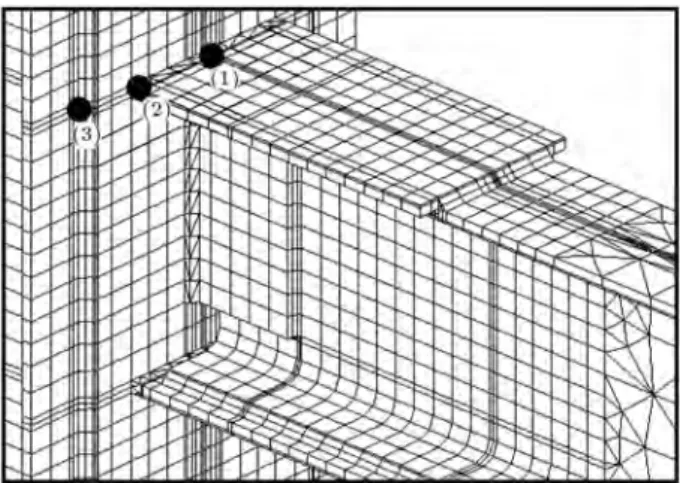
Figure 21. Critical points for calculating the strain indices.
connection, and a high PEEQ index would result in the failure of the structure. Three critical points (shown in Figure 21) are selected to show the PEEQ index and rupture index for connections retrotted with TPs (Figures 22-24). The PEEQ index is almost equal for all three points in the connection TPV. In addition, at point (2), the PEEQ index has a similar response with TPH M. The application of the triangular stiener plates reduces plastic strain by oering a new force ow path. The rupture index is high in the column welds and groove welds in model S-00 (points (2) and (3)). In the retrotted connections with only internal diaphragm plates, rupture would be initiated at point (2) due to its high rupture index.
The most important criterion in designing a mo-ment connection is formation of the plastic hinge away from the column face. In order to study the eect of dierent congurations on formation of the plastic hinge in the beam, the plastic equivalent strain (PEEQ) was computed from nite element analyses along a line at the mid-height of the beam ange, and through its length. The results are plotted in Figure 25 for six connections. Model S-00 shows no considerable inelastic strain demand along the beam ange. In other words, the plastic hinge could not be formed in the beam under the applied loads. Application of the T-stieners ensures formation of the plastic hinge
Figure 22. Response indices at point (1) vs. drift angle.
Figure 23. Response indices at point (2) vs. drift angle.
distant from the column face and connection elements. Similarly, retrotted connections with internal through plates increase the plastic demand in the beam anges far from the column face and connecting elements.
8. Conclusion
In this study, a common moment connection of I-beam to double-I built-up column was simulated and
Figure 24. Response indices at point (3) vs. drift angle.
Figure 25. PEEQ along the beam ange at 4% rad of drift angle.
evaluated under displacement control loading. While the present versions of Iranian building codes do not suggest these types of connection, their presence in old buildings needs further evaluation for retrotting purposes. Out-of-plane deformation of the column cover plate results in a semi-rigid behavior and also increases the failure potential during strong seismic motion. In addition, the load transfer mechanism in the connection is completely dierent from that assumed in the conventional design of previous versions of the building codes. The connection is retrotted using diaphragm plates from inside the column by modeling any possible congurations. The results show that the connections with a vertical plate can be suggested as an economical and feasible solution. In addition, application of T-stieners in retrotting projects was proposed to introduce a new smooth force ow path from the beam to the column, which provides
a reliable load transfer mechanism in the connection and causes the plastic hinge to be formed away from the column face. The local behavior of retrotted connections by T-stieners was also discussed. To reduce strain concentration in the connection elements, the horizontal element of the T-stiener was modied and then investigated. The results of this study conrm that a smaller angle ( = 30) between the beam
line and the outer edge of the horizontal element results in a better performance of connection type TSH. TSF connection types were also studied under similar boundary conditions and loading. Local and global responses indicate that TSF connections with = 45
have preferable responses.
References
1. Federal Emergency Management Agency (FEMA) \Recommended seismic design criteria for new steel momentframe buildings", Washington, D.C. FEMA-350 (2000).
2. Federal Emergency Management Agency (FEMA) \State of the srt teport on vonnection performance", Washington, D.C. FEMA-355D (2000).
3. Building and Housing Research Center (BHRC) \Ira-nian specications for design and construction of steel buildings", Tehran (2008).
4. Goswami, R. and Murty, C.V.R. \Externally rein-forced welded I-beam-to-box-column seismic connec-tion", J. Eng. Mech., 136(1), pp. 23-30 (2010).
5. Deylami, A. and Yakhchalian, M. \Behavior of two-way steel moment connections with side plates and double-I built-up columns under cyclic loading", The 14th World Conference on Earthquake Engineering, Beijing, China (2008).
6. Deylami, A. and Yakhchalian, M. \Comparison be-tween common moment connection and ment connec-tion with side plates for double-I built-up columns", The 14th World Conference on Earthquake Engineer-ing, BeijEngineer-ing, China (2008).
7. Deylami, A. and Yakhchalian, M. \The experimental study on buit-up column seismic resistant moment con-nections using side plates", The 14th World Conference on Earthquake Engineering, Beijing, China (2008).
8. Mazrooee, A., Simonian, W. and Nikkhah Eshghi, M. \Experimental evaluation of rigid welded connections used in Iran", Building and Housing Research Center, Tehran (1999).
9. Shanmugan, N.E., Ting, L.C. and Lee, S.L.\Behaviour of I-beam to box-column connections stiened exter-nally and subjected to uctuating loads", J. Constr Steel Res., 20(2), pp. 129-148 (1991).
\Box-column to I-beam connections with external stien-ers", 18(3), pp. 209-226 (1991).
11. Lee, S.L., Ting, L.C. and Shanmugam, N.E. \Use of external T-stieners in box-column to I-beam connec-tions", J. Constr Steel Res, 26(2-3), pp. 77-98 (1993).
12. Shanmugan, N.E., Ting, L.C. and Lee, S.L. \Non-linear analysis of I-beam to box-column connections", J. Constr Steel Res, 28(3), pp. 257-278 (1994).
13. Ghobadi, M.S., Ghassemieh, M., Mazroi, A. and Abolmaali, A. \Seismic performance of ductile welded connections using T-stiener", J. Constr Steel Res, 65(4), pp. 766-775 (2009).
14. Kiamanesh, R., Abolmaali, A. and Ghassemieh, M. \The eect of stieners on the strain patterns of the welded connection zone", J. Constr Steel Res, 66(1), pp. 19-27 (2010).
15. Goswami, R. and Murty, C.V.R. \Improved congura-tion of I-beam to box column conneccongura-tions in seismic steel moment frames", The 14th World Conference on Earthquake Engineering, Beijing, China (2008).
16. Arlekar, J. and Murty, C.V.R. \Improved truss model for design of welded steel moment-resisting frame connections", J. Struct Eng., 130(3), pp. 498-510 (2004).
17. ABAQUS \Abaqus/CAE user's manual", Providence, RI, USA, Dassault Systemes Simulia Corp. (2010).
18. American Institute for Steel Construction (AISC), \Specication for structural steel buildings", ANSI/AISC 360-05, Chicago, Illinois (2005).
19. El-Tawil, S.M., Mikesell, T., Vidarsson, E. and Sashi, K. \Strength and ductility of FR welded-bolted con-nections", SAC Joint Venture, Sacramento, California Report No. SAC/BD-98/01 (1998).
Biographies
Gholamreza Ghodrati Amiri received his BS and MS degrees in Civil Engineering from Sharif Uni-versity of Technology, Iran, and his PhD degree in Structural and Earthquake Engineering from McGill University, Canada. He is currently Professor at Iran University of Science and Technology. His research interests include seismic hazard analysis, performance-based earthquake engineering and structural health monitoring.
Mohsen Azimi received a BS degree in Civil Engi-neering from the University of Mohaghegh Ardabili, Iran, and an MS degree in Earthquake Engineering from Iran University of Science and Technology. His research interests include rehabilitation of structures, dynamic behavior of structures, optimization in civil engineering and earthquake engineering.
Ehsan Darvishan received his BS and MS degrees in Engineering from Iran University of Science and Tech-nology. His research interests include rehabilitation of structures, earthquake engineering and structural health monitoring.