TECHNICAL UNIVERSITY OF CLUJ-NAPOCA
ACTA TECHNICA NAPOCENSIS
Series: Applied Mathematics, Mechanics, and Engineering Vol. 60, Issue II, June, 2017
EQUIPMENT AND PROCEDURE FOR EXPERIMENTAL
DETERMINATION OF STATIC RIGIDITY OF ENGINE LATHES
Sergiu TONOIU, Mădălin-Gabriel CATANĂ, Nicolae IONESCU, Ionuţ-Gabriel GHIONEA
Abstract: As machining precision and productivity in a technological manufacturing system (TMS) depend on system rigidity, it is necessary to establish TMS rigidity accurately. This can be done with rigid test bars that do not influence TMS rigidity measurements. The test bars can be used for measuring rigidity of any machine tool or subassembly of a machine. This paper presents experimental equipment and procedure for determination of static rigidity of an engine lathe. Planar and spatial test forces were applied and corresponding deformations of different lathe’s subassemblies were measured. Obtained data can be used afterwards to assess the suitability of TMS for machining steps of different quality and to estimate the influence of TMS deformations on the accuracy of machined parts.
Key words: engine lathe, rigidity measurement, experimental equipment, test bar.
1. INTRODUCTION
Manufacturing precision and productivity in a technological manufacturing system (TMS) depend on its rigidity [1].
Generally, size and shape alterations of the manufactured parts are influenced by the static or quasi-static deformations of TMS, while deformations produced by various dynamic loads directly influence the roughness of the manufactured surfaces [1].
Forces applied to TMS may be static [1], quasi-static [2], or dynamic [1], while deformations of TMS elements under these forces may be static or dynamic.
Deformations of TMS elements are estimated through analytical calculations or through numerical techniques like finite element method (FEM) and their results are validated through experimental work [3].
Experimental determination of deformations in TMS implies a controlled loading of TMS with known forces and measurement of resulting deformations with adequate equipment [3], [4], and [12].
Quasi-static forces are applied by special equipment used frequently for modal analysis [2]. In this case, onto TMS being in static state
is applied a sinusoidal, low frequency force. The advantage of this procedure is the accurate determination of static rigidity of TMS, permitted by reduced influence of friction forces on TMS deformations. However, the procedure is costly to apply because extensive experimental work and expensive equipment are implied.
Within all TMS, rigidity of main spindle assembly (MSA) is crucial. Reference [5] shows a static and dynamic optimization of MSA, taking into account geometrical characteristics of spindle and bearings, and assembly characteristics like the number of bearings and distance between them.
Deformation of MSA is firstly determined through analytical calculations and results are validated experimentally. However, within this study were not taken into account loads on several directions on MSA. Also, no information is provided on specific equipment that is used for applying forces on MSA.
Static rigidity of TMS elements consisting in boring bars is studied by [7]. Three types of boring bars with different shapes are loaded with spatial forces. Their deformations are stated by analytical calculations, by FEM and experimentally. However, paper does not present the experimental equipment that was used for experiments.
Static rigidity of turning tools with different holders was determined experimentally by reference [8] and best holder in terms of rigidity was selected.
Different measurement and test techniques that may be used for determining interactions between manufacturing processes and TMS structures (including deformations) are described by [9].
Other experimental tests for determining the rigidity of lathes and lathes’ components are presented in [11] and [13].
2. THEORETICAL CONSIDERATIONS
A technological manufacturing system is a group of elements consisting in: machine-tool, tool and its fastening device, workpiece, device for fastening workpiece, all these elements working together in the manufacturing process [3] and [4]. TMS is generally considered as an elastic system [3].
In order to determine the rigidity of TMS, the basic elements regarding TMS structure, references, states, stresses and deformations must be known [3] and [4].
A TMS is a combination of physical elements, Ek, that are interdependent constructive and functionally [3] and [4]. An element Ek of TMS may be simple, like a tool, or complex (an assembly or subassembly of TMS).
Deformations of TMS depend on material and geometrical characteristics of its components and on characteristics of the joints between components with respect to couple of materials, roughness of contact surfaces, type of contact (dry or wet), contact pressure, fits between components, etc [3].
To define certain features of the TMS load or deformation, an appropriate geometrical three-orthogonal Cartesian reference system Oxyz must be used (Fig. 1).
A geometrical reference system can be attached to physical references (RF). A physical reference may be absolute, if it is exterior to TMS, or may be relative, if it is a part of TMS [3]. A geometrical reference system that is parallel to functional work directions of machine-tool in TMS is commonly used.
A TMS can be in one of the following four states: “rest”, “passive functioning (idle)”, “stable active functioning (machining)” or “unstable active functioning (machining)”, as stated in [3] and [4].
The static load F in TMS (Fig. 1) appears mainly between physical elements with direct contact, in a state of “rest”, “passive functioning (idle)”, or “stable active (manufacturing) functioning” of TMS. Static force is applied to a loaded element EF of TMS (Fig. 1).
Fig. 1. A generic load scheme of TMS [3] and [4].
In Fig. 1, the static load F (force) has the components Fx, Fy, Fz along X, Y, and Z axes of reference system Oxyz. AF is a point belonging to the element EF, identical to the application point of load F. rF is the position vector of point AF in relation to the origin of the reference system Oxyz.
The components of TMS are deformed (U) when the load F acts upon them. Direction and measuring point associated with deformation U are established according to each particular case.
Similar to the load, the deformation U has three components Ux, Uy, Uz along the X, Y, Z axes of reference system Oxyz (Fig. 2). To simplify, we will denote Ux as X, Uy as Y and Uz as Z.
Fig. 2. Schemes for measuring the TMS loads and deformations [3] and [4].
Fig. 3. A particular load scheme of TMS [3] and [4].
If AU is the measuring point of deformation, U and rU is the position vector of AU in relation to the origin of the referential Oxyz (Fig.1), then: if EU ≡ EF, then AU ≠ AF (Fig. 1, Fig. 2), or AU ≡ AF (Fig. 3).
Fig. 4 presents three schemes for measuring TMS planar loads and deformations: a) on main spindle assembly (MSA) without intermediary test bar; b) on MSA with intermediary test bar 1; c) on MSA with clamping chuck 2 that holds the test bar 1.
Fig. 4. Schemes for measuring planar loads and deformations of TMS: a) direct on MSA; b) on MSA with test bar; c) on MSA with test bar in clamping chuck
[3] and [4].
To measure spatial loads and deformations, a test bar 1 with element 2 of spherical shape “a”, is mounted in MSA (Fig. 5). This bar is the axis of MSA. The deformation is measured in the force application point (AU ≡ AF) with spherical head “b” connected to a deformation transducer.
Fig. 5. Test bar for measuring spatial loads and deformations of TMS [3].
Fig. 6 presents a measuring scheme for the carriage of a lathe. In tool holding turret of the lathe is mounted a prismatic part 1 with conical hole, in which is held the test bar 2. Carriage can be loaded on different directions through spherical element 3. The deformations are measured in the application force point.
Fig. 6. Scheme for measuring loads and deformations of lathe’s carriage [3].
For experimental determination of static rigidity for a TMS element, it will be subject to a progressive increasing load, whose value is measured at each level. The corresponding deformation is measured with an adequate instrument [3].
3. EXPERIMENTAL RESEARCHES
3.1 Equipment for rigidity measurement Different test bars were previously used for creating spatial forces on lathe spindles [10]. Test bar in Fig. 7 was used first in [3]. The assembly of spherical head 2 with the body 1 of the test bar is realized through a cylindrical fit “d” and thread “e”. Body 1 is provided with a conical or cylindrical shank. The load applied onto spherical feature “b” of part 2 is transmitted and measured onto feature “a” of part 1 through hole “c”. The main disadvantage of this solution is the low accuracy caused by the clearance fit between parts 1 and 2 on feature “d” and by the short distance existing between the threaded assembly feature “e” and the spherical feature “b” onto which loads are applied. These design weaknesses caused deformations of measured spherical feature “a” unrelated to real deformations of the axis of tapered body 1.
Fig. 7. Initial design of the test bar [3] and [10].
Fig. 8. Improved design of the test bar [10].
To increase the accuracy of the test bar, initial design was improved as shown in Fig. 8. Test bar in Fig. 8 consists of two elements: body 1 and spherical head 2. Assembly of the spherical head 2 with the body 1 is performed through the pressed conical fit “d” and the thread
“e”. Body 1 is provided with the spherical head “a” and hole “c” for the access of strain measuring transducers. Due to the pressed conical fit between parts 1 and 2 and the increased distance between the threaded assembly feature “e” and the spherical feature “a”, measuring accuracy of the test bar increases.
A second improvement of the test bar in terms of measuring accuracy and manufacturability is presented in Fig. 9. This consists of body 1 and pin 2 with spherical head “a”. This design ensures that deformation of measured spherical feature “a” isn’t influenced at all by deformation of loaded feature “b”, but only by real deformation of the axis of tapered body 1 (of the machine-tool spindle). Furthermore, compared to previous designs, the test bar in Fig. 9 is simpler and easier to manufacture.
Fig. 9. Extra improved design of the test bar [10].
Test bars in Fig. 7, Fig. 8 and Fig. 9 were experimentally tested by using FEM modules of Autodesk Inventor 2013 and Ansys 14 and by using experimental stand in Fig. 10. Performed experiments proved the superiority of test bar in Fig. 9 in terms of accuracy ensured for rigidity measurement of MSA. Test bar in Fig. 9 was integrated within measuring system in Fig. 10 for testing the rigidity of MSA of engine lathe SNA 500. Force F may be applied in a linear manner or spatially onto the test bar 2 provided with spherical element 3.
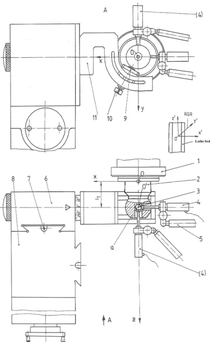
Fig. 10. Experimental equipment for measuring static rigidity of MSA for engine lathe SNA 500.
Fig. 11. Experimental equipment for measuring static rigidity of the carriage of engine lathe SNA 500.
Loading of MSA can be realized at a fixed axial position, l1 (Fig. 10). Relative geometrical reference (RGR) is associated to the lathe’s bed (Fig. 10).
A modified construction of stand in Fig. 10 for measuring the rigidity of the carriage of SNA 500 lathe is shown in Fig. 11. In this case, test bar is mounted on the cross slide of the lathe and dynamometric device is clamped on MSA.
3.2 Experimental data
- Test bar in Fig. 9 is used in experimental stand with construction in Fig. 10 or Fig. 11; - Relative physical reference: lathe’s bed; - Relative geometrical reference: O’x’y’z’; - Axial position: l1 = 65 mm, l2 = 65 mm; - Static force: Fx, Fy, Fxy, Fxyz [daN]; - Deformation: X, Y, Z [µm].
Experimental data are presented in Tables 1, 2, 3 and 4.
Table 1
Fx and Fy loadings. Fx
[daN]
X [µm] Fy [daN]
Y[µm] incr. decr. incr. decr.
0 0 0,65 0 0 0,9 50 7,30 7,65 50 7,7 8,1 100 14,60 15,75 100 15,2 16,4 150 20,90 22,05 150 21,7 22,9 200 27,45 27,80 200 28,4 28,9 250 32,00 33,10 250 33,2 34,4 300 38,25 39,00 300 39,7 40,5 350 42,50 43,10 350 44,1 44,6 400 44,50 44,50 400 46,1 46,1
Table 2
Fxy loading (ϕy = 30o). Fxy
[daN]
X [µm] Y[µm] incr. decr. incr. decr.
0 0 0,30 0 0,60
50 5,85 7,90 7,90 8,25 100 12,35 16,20 14,70 20,50 150 18,25 22,65 20,75 32,20 200 24,61 27,35 27,85 24,30 250 29,89 30,90 33,90 35,85 300 32,54 33,05 38,15 39,40 350 33,20 33,75 39,70 40,80 400 34,10 34,10 40,90 40,90
Table 3
Fxyz loading (ϕy = 30o and ϕz = 75o). Fxyz
[daN]
X [µm] Y[µm] Z[µm] incr. decr. incr. decr. incr. decr.
0 0 0,30 0 0,55 0 0,9 50 5,75 6,10 6,70 7,05 1,5 1,8 100 10,75 14,85 12,45 17,35 2,9 4,2 150 15,20 19,35 17,65 22,45 4,2 5,3 200 20,30 23,40 23,45 27,25 5,4 6,4 250 24,80 26,15 28,80 30,40 6,8 7,2 300 27,90 28,70 32,30 33,30 7,5 7,8 350 28,95 29,85 33,60 34,50 7,9 8,0 400 29,90 29,90 34,70 34,70 8,1 8,1
Table 4
Fxy loading (ϕy = 30o) of lathe carriage. Fxy
[daN]
X [µm] Y[µm] incr. decr. incr. decr.
0 0 1,8 0 2,3
50 2,5 13,2 6,1 9,4 100 6,6 19,1 14,5 17,7 150 8,7 26,3 21,9 23,2 200 14,5 29,6 29,3 30,7 250 20,1 33,1 36,6 38,7 300 26,2 35,5 43,4 45,6 350 33,7 38,9 49,9 52,9 400 40,6 40,6 56,1 56,1
Using data in table 1, MSA rigidity can be computed in daN/mm as follows:
8488 0445 0 400 X F
Kxx = x = =
, (1) 8776 0,0461 400 Y F
Kyy = y = = (2)
Using data in table 2, MSA rigidity can be computed in daN/mm as follows:
730 11 0341 0 400 X F
KPx = xy = =
, (3) 9779 0409 0 400 Y F
KPy = xy = =
, (4)
where P stands for the direction of planar force Fxy.
Using the data in table 3, MSA rigidity can be computed in daN/mm as follows:
377 13 0299 0 400 X F
KSx = xyz = =
, (5) 527 11 0347 0 400 Y F
KSy = xyz = =
, (6) 382 49 0081 0 400 Z F
KSz = xyz = =
, (7)
where S stands for the direction of spatial force Fxyz.
Using the data in table 4, lathe's carriage rigidity can be computed in daN/mm as follows:
9852 0406 0 400 X F
KPx = xy = =
7130 0561 0
400
Y F
KPy = xy = =
, (9)
where P stands for the direction of planar force Fxy.
4. CONCLUSION
Determination of static rigidity of lathes’ MSA and carriage claims for a particular work environment, which refers to the structure of TMS, references, system’s states, loadings and deformations.
This paper presents several schemes for measuring TMS loads and deformations, together with two constructions of an experimental stand that can be used for rigidity measurement of MSA and carriage of lathes. Several designs of the test bar that is used in experimental stand were also presented in the paper.
Proposed schemes and devised experimental stand may be used for measuring rigidity of other components of lathes, or of other types of TMS (with milling machines, grinding machines, etc.).
As shown by experimental data, the rigidity of lathe carriage is lower than the rigidity of MSA of lathe. This result is a direct consequence of the greater number of fixed and mobile joints that are used in the construction of carriage assembly as compared to MSA.
ACKNOWLEDGEMENT
The work of Ionuţ-Gabriel Ghionea has been funded by the Sectorial Operational Programme Human Resources Development 2007-2013 of the Ministry of European Funds through the Financial Agreement POSDRU/159/ 1.5/S/138963.
5. REFERENCES
[1] Weck, M., Werkzeugmaschinen, Band 4, Messtehnische Untersuchung, VDI-Verlag GmbH, Dusseldorf, 1990.
[2] Weck, M. et al., Methods for determination of machine tool static rigidity, Mechanik, 4(1989), pp. 125-129.
[3] Tonoiu, S., Contribution to the study of rigidity of technological manufacturing system,
PhD Thesis at University “Politehnica” of Bucharest, 1999.
[4] Gheorghe, M., Tonoiu, S., Fundamentals on loadings, deformations, rigidity and compliance of technological systems, Proceedings of the International Conference on Advances in Materials and Processing Technologies, 2003, pp. 1662-1665.
[5] Prakosa, T., Wibowo, A., Ilhamsyah, R., Optimizing static and dynamic stiffness of machine tools spindle shaft for improving machining product quality, Journal of KONES Powertrain and Transport, 20, 4(2013), pp. 363-370.
[6] Paulo Davim, J., Traditional Machining Processes - Research Advances, Springer-Verlag, Berlin-Heidelberg, 2015.
[7] Taskesen, A., Mendi, F., Kisioglu, Y., Kulekci, M.K., Deformation Analysis of Boring Bars Using Analytical and Finite Element Approaches, Journal of Mechanical Engineering, 52, 3(2006), pp. 161-169.
[8] Popescu, I., Tonoiu, S., Static stiffness of turning tools, Scientific Bulletin of “Politehnica” University of Bucharest, 72, 2(2010), pp. 115-122.
[9] Denkena, B., Hollmann, F., Process Machine Interactions - Prediction and Manipulation of Interactions between Manufacturing Processes and Machine Tool Structures, Springer-Verlag, Berlin-Heidelberg, 2013.
[10] Tonoiu, S., Catană, M., Tarbă, C., Design and Testing of Improved Test Bars for Measuring the Rigidity of Spindles of Normal Lathes, Proceedings of the 7th International Conference on Advanced Manufacturing Technologies, Bucharest, 2014, pp. 645-650. [11] Darbinyan, V.L., Esayan, P.M., Stiffness of an NC Lathe Carriage, Journal of Soviet Engineering Research, Volume 1, Issue 9, pp. 86-88, 1981.
[13] Hriesik, A., Testing Results of the Static Rigidity of the Lathe and Radial Drilling
Machine, Journal Strojarstvo, Volume 25, Issue 1, pp. 15-19, 1983.
Echipament şi metodologie pentru determinarea experimentală a rigidităţii statice a strungurilor normale
Rezumat: Deoarece precizia şi productivitatea prelucrării cu sisteme tehnologice de prelucrare (TMS) depind de rigiditatea sistemelor, este necesară determinarea precisă a rigidităţii TMS. Aceasta se poate realiza prin utilizarea unor echipamente care includ dornuri de control rigide, astfel încât să nu influenţeze precizia de măsurare. Dornurile de control pot fi utilizate pentru măsurarea rigidităţii oricărei maşini-unelte sau subansamblu al maşinii-unelte. Această
lucrare prezintă echipamentul şi metodologia utilizate pentru determinarea experimentală a rigidităţii statice a unui strung normal. Experimentele au implicat aplicarea de forţe planare şi spaţiale şi măsurarea deformaţiilor corespondente ale subansamblurilor strungului. Rezultatele obţinute privind rigiditatea pot fi utilizate pentru stabilirea adecvanţei TMS pentru realizarea de prelucrări de anumite precizii impuse şi, respectiv, pentru estimarea influenţei deformaţiilor TMS asupra preciziei de fabricare a pieselor prelucrate prin aşchiere.
Sergiu TONOIU, Phd. Eng., Professor, University Politehnica of Bucharest, Faculty of Engineering and Management of Technological Systems, Department of Machine Manufacturing Technology, E-mail: [email protected], Office Phone: +4021 402 9373, Address: Bucharest, Romania, Spl. Independenţei nr. 313, district 6.
Mădălin-Gabriel CATANĂ, Phd. Eng., Associate Professor, University Politehnica of Bucharest, Faculty of Engineering and Management of Technological Systems, Department of Machine Manufacturing Technology, E-mail: [email protected], Office Phone: +4021 402 9373, Address: Bucharest, Romania, Spl. Independenţei nr. 313, district 6.
Nicolae IONESCU, Phd. Eng., Professor, University Politehnica of Bucharest, Faculty of Engineering and Management of Technological Systems, Department of Machine Manufacturing Technology, E-mail: [email protected], Office Phone: +4021 402 9373, Address: Bucharest, Romania, Spl. Independenţei nr. 313, district 6.
![Fig. 1. A generic load scheme of TMS [3] and [4].](https://thumb-us.123doks.com/thumbv2/123dok_us/7999647.2120911/2.892.442.778.511.694/fig-generic-load-scheme-tms.webp)
![Fig. 9. Extra improved design of the test bar [10].](https://thumb-us.123doks.com/thumbv2/123dok_us/7999647.2120911/4.892.95.373.776.983/fig-extra-improved-design-test-bar.webp)