ClearPath
FS1770 System
Implementation Guide
FS1770 1.0
responsibility that may be the result of your use of the information in this document or software material, including direct, special, or consequential damages.
You should be very careful to ensure that the use of this information and/or software material complies with the laws, rules, and regulations of the jurisdictions with respect to which it is used.
The information contained herein is subject to change without notice. Revisions may be issued to advise of such changes and/or additions.
Notice to U.S. Government End Users: This is commercial computer software or hardware documentation developed at private expense. Use, reproduction, or disclosure by the Government is subject to the terms of Unisys standard commercial license for the products, and where applicable, the restricted/limited rights provisions of the contract data rights clauses.
Section 1. Introduction
Documentation Updates . . . 1–1 Audience . . . 1–1 Media . . . 1–1
Section 2. Customizing the System Configuration
Configuring a Management Workstation . . . 2–1 Configuring I/O . . . 2–2 I/O Services . . . 2–2 Configuring Storage . . . 2–2 Determining Correspondence Between MCP Storage
Channels and Firmware Environment Storage
Controllers . . . 2–4 Determining Correspondence Between MCP LUNs
and Firmware Environment LUNs . . . 2–5 Determining Correspondence Between MCP Logical
Disks and Firmware Environment LUNs . . . 2–6 Hot Reuse of Fibre Channel in a Channel Group is Not
Supported . . . 2–7 Enabling and Disabling Fibre Channel Ports . . . 2–7 Configuring the Network. . . 2–8 Network Services . . . 2–9 Default Networking Configuration . . . 2–9 Using Tools Associated with Network Services . . . 2–10 Changing the Network Services EVLAN IP Address . . . . 2–11 Supporting MCP Network Adapters. . . 2–12 Preparing to Use Adapter Teaming and IEEE 802.1Q
Virtual LANs . . . 2–13 Preparing to Use Jumbo Frames . . . 2–14 Using the System Editor to Configure MCP
Networking . . . 2–16 Sample ADAPTERS.TXT File . . . 2–19 Updating the MCP View of the Network . . . 2–19 Changing the Administrator User Name and Password . . . 2–21 Changing the Default Systems Management Account Password. . . 2–22 Configuring the MCP Environment . . . 2–23 Configuring Call Home Services . . . 2–23
Configuring and Using the Open Management Interface (OMI) . . . . 2–24
Section 3. Operating the System
Managing Power . . . 3–1 Viewing Platform Hardware Power Status . . . 3–1 Accessing the BMC Web Interface . . . 3–1 Powering On theSystem . . . 3–2 Monitoring Platform Boot Progress . . . 3–2 Shutting Down the System . . . 3–3 Powering Off Platform Hardware . . . 3–3 General Environment Operational Tasks . . . 3–3
Viewing the Status of the MCP Operating
Environment. . . 3–4 Restarting or Resetting the MCP Operating
Environment. . . 3–4 Operating the MCP Operating Environment . . . 3–4 MCP Firmware Environment Policy . . . 3–4 Policy Services . . . 3–5 Firewall Rules. . . 3–6 Network Authentication . . . 3–7 Audits . . . 3–7 MCP Firmware Environment Policy Utility Scripts . . . 3–8 Enabling MCP PING Commands through the EVLAN Connection . . 3–10 Synchronizing Time . . . 3–12 Network Services . . . 3–12 Differences from Previous MCP Systems . . . 3–12 Configuring MCP Networking . . . 3–13 Initializing Network Services . . . 3–13 Verifying Network Services Installation and
Configuration . . . 3–13 MCP Operations Interface Summary . . . 3–15 Networking Commands and Inquiries. . . 3–17 System Commands and Inquiries. . . 3–19 Call Home Services. . . 3–19 Using Maintenance Mode. . . 3–20 Testing E-mail Alerts . . . 3–20 Testing E-mail Heartbeats . . . 3–20 I/O Services . . . 3–20 I/O Time for VSS Disks . . . 3–21 Performing Dynamic PCD Updates . . . 3–21 Power Cycling or Disconnecting Fibre Channel I/O
Section 4. Backing Up MCP Firmware Configuration Data
Backing Up MCP Configuration Data . . . 4–1 Backing Up a Logical Disk . . . 4–2
Section 5. Updates
Using Interim Correction (IC) Update Files . . . 5–1 Accessing and Downloading Updates . . . 5–1 Updating Firmware Using the Master Installation Manager
Update Script . . . 5–2 Updating MCP Firmware. . . 5–2 Driver and PCI Card BIOS/Firmware Updates . . . 5–3 Updating Network Services. . . 5–3 Removing Network Services . . . 5–3 Reinstalling Network Services . . . 5–4 Updating Environment Operating System Software . . . 5–4
Section 6. Troubleshooting and Recovery
Submitting Trouble Reports . . . 6–1 Accessing the Unisys Product Support Website . . . 6–2 Using Remote Support . . . 6–3 Using Call Home. . . 6–3 Monitoring the Call Home Event E-mail Messages . . . 6–3 Using Maintenance Mode. . . 6–3 Problems with Call Home . . . 6–4 Restarting the MCP Operating Environment. . . 6–4 Diagnostic Tasks . . . 6–4 Generating an MCP Environment Dump . . . 6–4 Generating an MCP Firmware Environment Dump . . . 6–5 Transferring Diagnostic Data to Unisys Product
Support . . . 6–5 Platform Hardware Failure Scenarios . . . 6–5 MCP Environment Failure Scenarios . . . 6–7 System Startup Problems . . . 6–7 Problems Mapping to a Client Access Services Share. . . . 6–8 Fatal system Error. . . 6–8 Network Services Failure Scenarios . . . 6–9 Initiating a Dump . . . 6–9 Troubleshooting Fibre Channel I/O Problems . . . 6–13 Recovery Actions . . . 6–15 Restoring a Logical Disk . . . 6–16 Restoring the Halt/Load Unit Logical Disk File . . . 6–16
Power-Cycling the System. . . 6–17 Reinstalling the System. . . 6–17
Appendix A. Building Network Initialization Files
Preconfigured CNS and TCP/IP Initialization Files . . . A–1 CNS and TCP/IP Initialization Files . . . A–1 Guidelines for Building CNS Initialization Files . . . A–1 Guidelines for building TCP/IP Initialization Files . . . A–2 Preconfigured SNMP Initialization File . . . A–4 SNMP Initialization File . . . A–4 Guidelines for Building BNA Initialization Files . . . A–6 Using NAU Network Version Dump Files. . . A–7
2–1. Physical Location of HBA Ports to Entries in Device Manager or Channels
Listed by the SC+ ODT Command. . . 2–5 2–2. Default IP Address Values for MCP on the FS1770 System . . . 2–10 2–3. Default Networking Values on the FS1770 System. . . 2–10 2–4. MCP Networking Values Configuration Worksheet for FS1770 System . . . 2–20 2–5. MCP Networking Values. . . 2–20 3–1. Unisys-Defined Firewall Rules for MCP Functions . . . 3–6 3–2. MCP Firmware Environment Policy Audit Policy Settings . . . 3–7
Introduction
This document describes the FS1770 System, its capabilities, hardware components, supported system and application software, and the services provided to support system operation.
Documentation Updates
This document contains all the information that was available at the time of publication. Changes identified after release of this document are included in problem list entry (PLE) 19048381. To obtain a copy of the PLE, contact your service representative or access the current PLE from the product support website:
http://www.support.unisys.com/all/ple/19048381
Note: If you are not logged into the product support site, you will be asked to do so.
Audience
The audience for this document includes:
• ClearPath system administrators
• ClearPath network administrators
• ClearPath system operators
• Unisys service representatives
Media
The following media are required when configuring your system:
• ClearPath MCP Release SoftwareCD-ROM
• Interim Connections (ICs) are available atwww.support.unisys.com
• Keys media
Customizing the System Configuration
This section discusses issues you should consider for customizing the configuration of the FS1770 System. You should perform these tasks after your service representative sets up the system.
Configuring a Management Workstation
You perform systems management tasks for the FS1770 System either on the FS1770 System or on a management workstation.
You can configure your management workstation by downloading the MCP Workstation package from the Unisys Product Support Site. This package contains the systems management software required to manage the FS1770 System.
The ReadMe file for the MCP Workstation package contains the system requirements that your workstation must meet in order to be compatible with the FS1770 System. The ReadMe also provides installation instructions for the MCP Workstation package. To properly configure your management workstation, review the information and perform the procedures in this ReadMe file.
To access the ReadMe file, follow these steps:
1. Go to the Unisys Product Support Site atwww.support.unisys.com. 2. Log on to the website or register if you are a new customer.
3. UnderClearPath MCP Servers and Software, click FS1770 System from the
MCP Mainframeslist.
The Support Site for your system appears.
4. UnderSupport Options, clickDrivers and Downloads. The Drivers and Downloads page appears.
5. On the Hardware tab at the bottom of the page, click theWorkstationlink in the
Operations Workstationcategory. The Workstation page appears.
6. UnderLevel Information, click the link for the latest release level of the software. The MCP Workstation package page appears.
7. UnderDownload Information, click the link for the ReadMe file (for example,
MCPWorkstation-Readme.htm), open the file, and follow the instructions to install the workstation package.
Configuring I/O
This subsection provides topics to consider when setting up your I/O configuration on the FS1770 System.
I/O Services
I/O services represent the portion of the MCP Firmware that supports MCP I/O to the following types of devices:
• Disk and disk storage systems
• Tape and tape libraries
• Virtual tapes
• Operator Display Terminals (ODTs)
• DVD-RW drives
I/O services are responsible for the discovery and management of devices, and
performing I/O operations. They also support Plug-and-Play, which enables you to add new channels, taps, and disks to the MCP without a halt/load. These services run on MCP Operating Environment.
Configuring Storage
The FS1770 System supports both VSS and Logical disks. You can configure logical disks on internal or external storage. However, you can only configure VSS disks on the external disks.
Note: External storage must be either all VSS disks or all logical disks.
Each VSS disk on the FS1770 System supports up to eight active I/Os, which enables the FS1770 System to potentially achieve improved I/O performance when dividing disk families into fewer members.
The number of LUNs needed for satisfactory performance varies based on many factors, including the data access patterns of your applications. Each logical disk on the FS1770 System is created by the Logical Disk Manager (LDM) and is actually a file on the underlying operating system. Because this is a file in the file system, the underlying operating system takes advantage of memory caches that optimize the I/O throughout. Refer to theDisk and Tape Storage Systems Configuration Guidefor detailed information and restrictions that must be followed when configuring disk and tape storage.
Storage and Networking Ports
The system supports the following customer options (6 cards) from the following choices:
• 0–3 NICs in addition to the LOM2 port for MCP use.
• 0 to 3 NICs, each can be either
- Quad port, copper, 1 Gb NIC — Intel i350–T4 (Unisys Style ES3503014–PCE)
- Dual port, optical, 10 Gb NIC — Intel X520–SR2 (Unisys Styles ES3503023–PCE [adapter] and ES2590122–PCE [optical transceivers] together)
- Dual port, copper, 10 Gb NIC — Intel X540–T2 (Unisys Style ES3503026–PCE)
• 0–3 HBAs, each can be either
- Dual port, 8Gb FC—Emulex LPe 12002
- Dual port, 16 Gb FC — Emulex LPe 16002B
- SAS External Tape Controller
The Fibre Channel HBA ports can be used to access a disk storage system. Direct connect and fabric configurations are both supported. In the case of a fabric configuration, each HBA port can be given access to either one or two taps in the storage system.
For configurations with a resilient storage system, at least two HBA cards must have paths that provide access to the storage system. These paths should use the storage ports in at least two storage processors/directors within the storage system. To achieve the best resiliency in a fabric configuration, the paths must traverse two physically separate fabrics.
Refer to theDisk and Tape Storage Systems Configuration Guidefor details on available Fibre Channel HBAs for your configuration.
I/O Management Tools
The FS1770 System is equipped with the following user interfaces that you use to manage the I/O on the system.
OCManager
You access the OCManager installed in the MCP Operating Environment to display useful I/O subsystem information. However, you should not use it to adjust system settings unless directed by Unisys support. In particular, do not set persistent binding on the storage logical units (LUNs).
System Editor
You use the System Editor of the MCP Console to create a peripheral configuration diagram (PCD) that describes the FS1770 System storage configuration. PCD creation is fully automated on the FS1770 System. You only need to select those devices that the MCP is to use, optionally adjust the device numbers used to identify devices, and add comments about the devices. Comments placed into the PCD are visible in some of the MCP screen displays.
For more information on System Editor, see theMCP Console Help.
Determining Correspondence Between MCP Storage Channels
and Firmware Environment Storage Controllers
Use the information in this subsection to determine the correspondence between the physical HBA cards, storage controller ports in Device Manager, and channels in the MCP displays and the System Editor of the MCP Console.
Note: VIRTUAL channels do not possess these attributes and are created to make the presentation of the virutal disks more in line with the physical disks.
In the MCP Environment
Start an ODT session on the management workstation and use the SC+ command to display detailed I/O configuration. The HBA location information for each channel is displayed as shown in the following example:
CHANNEL <#> IOP 1 TYPE PCI POSITION 0,1,0 Emulex LPe15004-M8, PCI Slot 5, {
The three numbers (0,1,0) that follow POSITION correspond to bus, device, and function in that order. The slot number is listed after the description of the HBA.
In the Firmware Environment
Follow these steps:
1. On the desktop, right-click theStartbutton and selectDevice Manager. 2. Expand theStorage controllersnode.
3. To locate the slot, device, and port numbers, right-click an HBA and select
Properties.
ThePropertiesdialogue box appears.
You can find the slot, device, and port information in theGeneraltab.
Example
For a dual-port HBA in slot x, there are two entries listed with the same slot number. The two entries share the same device number, one specifies function 0 and the other function 1.
4. Refer toTable 2–1for the correspondences of the physical location of the cards to the HBA entries in Device Manager and the Chanels displayed by the SC+ ODT
command.
Table 2–1. Physical Location of HBA Ports to Entries in Device Manager or Channels Listed by the SC+ ODT Command
Physical Location
Device Manager MCP Slot Port
X 0 Storage controllers Emulex LPe16002B, PCI Slot X,{
Location: PCI Slot X (PCI bus b, device 0, function 0)
CHANNEL <X> IOP 1 TYPE PCI POSITION b,0,0
Emulex LPe16002B, PCI Slot X,{
1 Storage controllers Emulex LPe16002B, PCI Slot X,{
Location: PCI Slot X (PCI bus b, device 0, function 1)
CHANNEL <X> IOP 1 TYPE PCI POSITION b,0,0
Emulex LPe16002B, PCI Slot X,{
Determining Correspondence Between MCP LUNs and Firmware
Environment LUNs
Each storage device has a SCSI address assigned in Windows that represents a real connection from the HBA to the storage device. This SCSI address comprises port, bus, target, and LUN. Bus and LUN numbers are sometimes virtualized and do not represent the actual hardware values.
In the IOA system MCP, the SCSI address consists of the physical bus, target, and LUN relative to a channel (HBA port). The bus and LUN values might differ from what Windows displays. The LUN value used by the MCP matches the physical LUN value in the storage system. When presenting a physical device like a Virtual Sector Size (VSS) disk or tape in the PCD, the physical LUN, SCSI Device ID, and worldwide name (WWN) of the device are included to unambiguously identify the device and validate that multiple paths to the device are really going to the same device.
Because Windows LUN numbers are logical and can change based on the order of device discovery, the mapping between actual devices, such as a VSS disk, in the MCP displays and the Device Manager or Disk Manager displays in the MCP Firmware operating environment is not fixed.
To view information about the disk:
1. Right click on a VSS disk inDevice ManagerorDisk Manager.
A VSS tab appears that presents MCP information about the disk that enables you to determine which MCP disk corresponds to this device. Note that this method is not helpful for finding the Device Manager object for an MCP disk if you have a large number of disks.
2. Search the diagnostic device tree file to find the Windows objects that correspond to an MCP disk. This file is in theC:\ProgramData\Unisys\MCP
Firmware\IO\DeviceMapdirectory in the MCP Operating Environment .
When the MCP initializes an I/O device in the PCD, the I/O Services firmware components use the information from the PCD to identify the corresponding Windows device, to open it, and to use it for subsequent I/O operations.
Determining Correspondence Between MCP Logical Disks and
Firmware Environment LUNs
Use the information in this subsection to determine the correspondence between the logical disks declared in LDM and the MCP displays and the System Editor of the MCP Console. Each logical disk is a file on the underlying operating system. It is represented as using an .asd system file. .
Note: This file is considered a system file and might be hidden in the file explorer. See the section “Viewing Logical Disk Files” inBacking Up a Logical Disk.
Logical disks are created by the Logical Disk Manager (LDM). Once a logical disk is created by the LDM, it can then be picked up by the System Editor of the MCP Console and included in the PCD. A logical disk will be seen by the MCP as a 180 byte formatted disk. It can be RC’d and supports each of the different directory formats. There is only one path to a logical disk that the MCP sees (even if there are multiple paths through EMC PowerPath on external drives). The logical disk file appears as a file on the mounted drive in the file explorer. To identify the logical disk from the MCP look under the VIRTUAL channel to see the disks:
CHANNEL<number>: IOP 1 TYPE VIRTUAL Virtual Controller
PK 1201 LUN 1 UNISYS UNISYS 020971M2 [0000] C:\disk0000.asd
PK 1202 LUN 2 UNISYS 001048M2 [0000] E:\TestDisk1.asd
PK 1203 LUN 3 UNISYS 003145M2 [0000] G\TestDisk3.asd
PK 1204 LUN 4 UNISYS 004194M2 [0000] G:\TestDisk4.asd
Notice that the actual file used for the logical disk is given (for example C:\disk0000.asd). From this output, the other discernible attributes are the size of the logical disk or the first several digits of the size. After the LUN number and UNISYS you will see a value
ssssssM2 [0000] where s is the relative size in MB (size specified * 1,048,576 bytes) with the last 6 digits truncated.
Hot Reuse of Fibre Channel in a Channel Group is Not Supported
Do not disconnect a Fibre Channel device from an HBA and connect a different device to the same HBA, as the system does not support the dynamic deletion of fibre devices while the MCP is running. When these fibre devices are a part of a channel group, the MCP has a working knowledge of all paths to a device. If those paths are changed while the MCP is running, it creates confusion that can only be resolved by halting the MCP and loading the new configuration.You cannot reuse a Fibre Channel if the following conditions exist:
• The MCP is running.
• The path to devices that are being added is replacing the path to devices already “owned” (usage equals MCP Use) by the running MCP.
• The path being removed is part of a channel group containing multiple channels.
• The path being added is not connected to the same string of devices that was removed.
Enabling and Disabling Fibre Channel Ports
During the FS1770 System installation process, all unused Fibre Channel ports are
disabled to allow faster environment startup times. If you connect additional Fibre Channel ports at a later time, you must enable those ports.
To enable or disable Fibre Channel ports, perform the following steps on each ISM with unused Fibre Channel ports:
1. Record the unused ports as follows:
a. Locate the unused HBA ports on the back of the ISM. The HBA slot number is stamped near the HBA slot.
b. For each unused HBA port, record the slot number and port number. Notes:
• For a rack-mounted system, Port 0 is on the top and Part 1 is on the bottom.
• For a tower configuration, Port 0 is on the left and Port 1 is on the right. 2. Disable the unused port(s) as follows:
a. Right-click theStartbutton and selectDevice Manager. b. Expand theStorage Controllersnode.
There will be two entries listed for each dual-port HBA which will all have the same slot number.
c. Right-click each HBA in the list that identifies a slot number from the list of ports to be disabled and then selectProperties.
d. Under the General tab, find the location information which is of the form:
PCI Slot X (PCI bus Y, device N function Z)
For the HBA in slot X, there will be four entries listed for a quad-port HBA and two entries listed for a dual-port HBA. For quad-port HBAs, the location information is displayed as follows:
PCI Slot X (PCI bus Y, device N function 0) PCI Slot X (PCI bus Y, device N function 1)
Note: For dual-port HBAs, only the first two entries of the location information is displayed.
e. Match the recorded information for the unused HBA ports to the location information as follows:
Dual Port HBA
Unused HBA Port Location Information from Properties
Slot X, Port 0 PCI Slot X (PCI bus Y, device N function 0) Slot X, Port 1 PCI Slot X (PCI bus Y, device N function 1)
f. If the device and function number in the Location information matches one of the unused HBA ports recorded earlier, click theDrivertab, and then clickEnableto enable the HBA port orDisableto disable the HBA port.
Continue through the list of HBA ports to match and enable or disable the slot-port pairs that you recorded earlier.
Configuring the Network
When you initially receive the FS1770 System, a default networking environment has been established using the following pre-configured initialization files:
CLEARPATH/INIT/CNS CLEARPATH/INIT/TCPIP
You can use the FS1770 System without modifying the default network configuration. However, you may want to integrate the system into your existing network. The following topics describe the general steps required to configure Network Services to operate within your network environment.
Network Services
Network Services encompasses a set of software services that enable the network interfaces of the MCP Operating Environment. These services include:
• A local Enhanced Virtual LAN (EVLAN) network connection between the MCP Environment and the MCP Operating Environment. Communication across the EVLAN is through the TCP/IP protocol. EVLAN supports the Call Home platform service developed by Unisys. The EVLAN connection is not used by customer applications.
• MCP network adapter services which enable TCP/IP and Heritage Network Services (BNA) network providers in the MCP Environment to establish network connections through NIC adapters of the underlying MCP Operating Environment. These services run on the MCP Operating Environment.
Network Processors
The FS1770 System supports up to six network processors (NPs) of type VNP. Each NP supports up to eight MCP network adapter connections.
The system is preconfigured with one NP, NP 210. Additional VNP devices are created for each PCI Express network adapter that is detected when System Editor is run. The additional VNPs are assigned the adapter ports of the NICs in the PCI Express slots. The MCP network adapter supports BNA and TCP/IP transfers to and from the MCP
Environment.
Default Networking Configuration
The following text describes the default networking configuration for your system.
• The default host name of the MCP system for the environment is CPMCP1.
• You use the System Editor of the MCP Console to assign NP numbers and Line IDs to the network interfaces within the MCP Operating Environment according to the following rules.
- The intra-system connections for a system are located on the initial NP defined for the MCP Operating Environment .
- The Line ID assignments for the intra-system connections are pre-assigned and cannot be modified.
Default Networking Values
The following tables provide default networking values.
Default Intra-System NP Instance Numbers
Default NP Values for External Connections
The NP instance and line ID number assignments for the MCP Operating Environment for add-on network interface cards (NICs) that are used for external connections for MCP use are based on the adapter SlotX/PortX of the device. The following equation is used to define the expected network processor instance numbers for the MCP Operating Environment :
NP instance number = 210 + slot number
For add-on NICs, the default Line ID value equals the port number of the device.
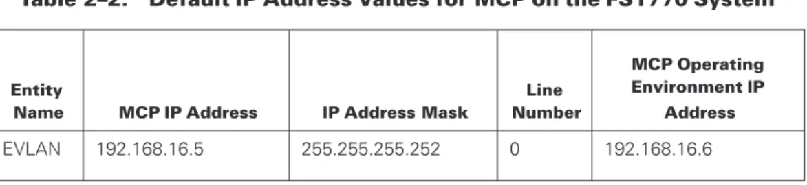
Default IP Address for Intra-System Connection
Table 2 lists the default IP addresses for the intra-system connections in the FS1770 System.
Table 2–2. Default IP Address Values for MCP on the FS1770 System
Entity
Name MCP IP Address IP Address Mask
Line Number
MCP Operating Environment IP
Address
EVLAN 192.168.16.5 255.255.255.252 0 192.168.16.6
Default MCP Operating Environment Networking Values
The following tables provide a summary of the standard configuration for the MCP Operating Environment.
Table 2–3. Default Networking Values on the FS1770 System
PCI Slot Network Port NP Number Line ID IP Address
None EVLAN 210 0 192.168.16.5 None LOM 2 210 2 192.168.237.50
Using Tools Associated with Network Services
The ClearPath network administrator installs and configures Network Services using the following tools in the MCP Console and MCP Operating Environment.
In the MCP Operating Environment
The NIC Configuration Manager enables you to manage settings, teaming, and virtual LAN configurations for MCP connections of add-on NICs.
In the MCP Console
The following tools are available in the MCP Console:
• System Editor
• MCP network diagnostics
For information on other helpful tools in the MCP Console, see theMCP Console Help.
In the MCP Environment
The following tools are available in the MCP Environment:
• Simple Installation program which supports installation of the network providers and supporting utilities
• Network Administrative Utility (NAU) or a file editing program such as CANDE. Generally, you use only one of these methods to configure TCP/IP and EVLAN connections.
- Use the NAU to create new (or edit existing) CNS, TCP/IP, and BNA (optional) initialization files for this ClearPath system complex. These files define all TCP/IP, Network Services EVLAN, and Network Services MCP network adapter
connections. Most often, you use NAU in installations that include Heritage Network Services (BNA) since it can ensure that the BNA initialization files are consistent on all of the ClearPath MCP hosts in your network.
- Use an editor such as CANDE to make necessary modifications to sample CNS and TCP/IP initialization files that are provided with the ClearPath system. Refer to Appendix A, Building Network Initialization Files, for a description of these sample initialization files.
Changing the Network Services EVLAN IP Address
Unisys recommends that you do not change the IP address and subnet mask for Network Services (EVLAN path). However, you may want to change these addresses if you already have nodes in your network using the same subnet. In this case, choose a different private set of IP addresses that do not conflict with the subnets in your network. Modify the EVLAN IP address and mask through the System Editor. Refer toUsing the System Editor to Configure MCP Networkingfor more information.
Notes:
• The Internet Assigned Numbers Authority (IANA) has reserved Class C addresses 192.168.0.0 through 192.168.255.255 for use within private networks (see RFC 1918).
• Changing the IP addresses of the EVLAN path is likely to require updates to the firewall rules of the FS1770 System. SeeMCP Firmware Environment Policy Utility Scriptsfor more information. Call Home functionality might also be affected. Refer to the appropriate Call Home documentation for more information.
Supporting MCP Network Adapters
MCP network adapters provide MCP access to qualified NICs, operating at speeds ranging from 10 megabits per second to 10 gigabits per second. Although the MCP network adapter software service allows connection to networks comprised of high-performance technologies, the actual data transfer rate might be less than the potential maximum for that network technology. For example, a 10 Gb Ethernet MCP network adapter allows the MCP system to participate on a 10–Gb Ethernet backbone, but the MCP does not transfer data at the maximum 10 Gb Ethernet transfer rate.
Network Services supports up to eight MCP network adapter connections per NP—where a connection is an Ethernet port, IP over InfiniBand adapter, 802.1Q Virtual LAN (VLAN) connection, or adapter team. In essence, the ClearPath Network Services view of an adapter is the same as that of the MCP Operating Environment view of the adapter. If it shows up as an entity to be managed within the Network Connections list of the Network and Sharing center within Control Panel, then you can configure the network adapter for MCP uset. This is accomplished through the MCP networking entities listed by the System Editor and using one of the MCP network adapter connections for a network processor.
Network Services supports up to six network processors per MCP Operating Environment on the FS1770 System. Both TCP/IP and Heritage Network Services (BNA) are supported to and from the MCP Environment through MCP network adapter connections. The use of Heritage Network Services might require the purchase of additional MCP software licenses beyond the base Integrated Operating Environment package.
Configuring MCP Network Adapter Settings
Network adapter settings are configured through the NIC Configuration Manager—a tool that gathers adapter information and enables you to change such NIC settings as TCP offload capabilities, adapter team management, and VLAN management.
You access the NIC Configuration Manager from the FS1770 System desktop.
Setting the Local Address
To override the factory-assigned MAC address of a network adapter on the FS1770 System, set the MAC address through the NW ADD CONNECTIONGROUP command in the CNS initialization file.
Note: You must set the local address through the ADD CONNECTIONGROUP
Disabling TCP Offload Settings
TCP Offload Engine (TOE) options within the advanced adapter settings of a NIC are incompatible with MCP use of adapters. Turn off all TOE features on any adapters that are to be used by ClearPath MCP networking, including such features as:
• IPv4 Checksum Offload
• Large Send Offload
• TCP Checksum Offload
• UDP Checksum Offload
Preparing to Use Adapter Teaming and IEEE 802.1Q Virtual LANs
You use the NIC Configuration Manager to create adapter teams and virtual LANs (VLANs). For instructions on using this tool, see the NIC Configuration Manager help, available from the interface under HELP MENU.Before creating adapter teams or VLANs, review the following information to ensure that the adapter teams and VLANs are configured properly.
Overview
Network Services MCP network adapter software supports adapter teaming and 802.1Q VLANs.
Adapter Teaming
When you create an adapter team, the system and user programs see a single virtual adapter team instead of the individual adapters that make up the team. You can use adapter teaming to provide fault tolerance at the adapter level (ClearPath MCP Network providers TCP/IP and BNA have alternate means of providing fault tolerance as well). Notes:
• Although adapter teaming can also be used to distribute network traffic across
multiple adapters on the same FS1770 System, this type of team is not recommended as it offers marginal value for ClearPath MCP customers.
• Teaming of IP over InfiniBand adapters isnotsupported at this time.
IEEE 802.1Q VLANs
IEEE 802.1Q VLANs enable a single network adapter to segregate its traffic among two or more virtual LANs. Each VLAN on an adapter is represented by a separate network adapter entry within the Network Connections Control Panel applet, effectively making a single adapter appear to Network Services as more than one adapter. IEEE 802.1Q VLANs are based on the addition of a 4-byte tag to the packet header, identifying the VLAN for that packet.
If the FS1770 System is a member of only one VLAN on a given adapter port, tagging is not necessary on that port. Turn tagging off at the switch port and configure the LAN Switch port to be a member of the appropriate VLAN instead. If the FS1770 System is to be a member of multiple VLANs over the same adapter port, then both the LAN switch and the FS1770 System must be configured. The switch connected to the FS1770 System must support IEEE 802.1Q tagging.
Modifying Adapter Settings for VLANS and Teaming
Perform the following steps to modify the adapter settings for VLANs and teaming: 1. At the switch, tagging should be enabled, and all VLAN ID assignments made at the
specific port. Follow any other vendor-specific instructions that might exist.
2. On the FS1770 System, use the NIC Configuration Manager to build adapter teams and configure VLANs. You must have administrative privileges to use the NIC Configuration Manager.
For more information on using this tool, see the NIC Configuration Manager help, available from the interface underHELP MENU.
Note: Before creating adapter teams or VLANs, you must use the System Editor to remove all MCP assignments from the adapters that you want to modify and save the changes. For more information on using the System Editor, seeUsing the System Editor to Configure MCP Networking.
3. For each VLAN defined and each adapter team defined, a new adapter is created. Use the System Editor to assign the new adapters to NPs and line IDs on the MCP. For more information on using the System Editor, seeUsing the System Editor to Configure MCP Networking.
4. Update the CNS and TCP/IP initialization files on the MCP to reflect the changes to the line availability (NP/line ID pair).
Preparing to Use Jumbo Frames
Jumbo frames are large Ethernet frames used in high-performance networks (up to 9000 bytes of payload) to increase performance over long distances. Jumbo frames improve ClearPath throughput and reduce the CPU cycles used for networking. This improvement is achieved by reducing the number of frames an application must process. This
improvement is particularly beneficial for applications that use large message sizes, such as file transfers. The remote system and the connecting network equipment along the entire communications path must support jumbo frames to use this feature effectively. You can use jumbo frames with TCP/IP, BNA, and BNA over IP (BIP). In addition to the application message size, the performance benefits vary depending on which of these protocols you use.
You must configure jumbo frames within ClearPath MCP Networking. You must perform modifications on the system where the adapter exists.
Configuring Jumbo Frames
Perform the following steps to configure jumbo frames on an adapter: 1. Start the NIC Configuration Manager.
2. Right-click the adapter that you want to modify, and clickSettings.... 3. Select the*JumboPacketproperty.
4. Select one of the values in the drop-down menu. The proper value depends upon the capabilities of your network switching equipment.
5. ClickApply, and then clickOK.
6. Within the MCP, you must set the following attributes to desired values for applicable lines (Connection Groups) and devices (Connections):
• Max Input Message Size (MIMS)
• Max Output Message Size (MOMS)
• Max Input Message Size Limit (MIMSL)
• Max Output Message Size Limit (MOMSL)
The recommended frame size for Jumbo Frames is 9014, including the MAC header, but excluding the Cyclic Redundancy Check (CRC). Configure this value in the NIC driver and translate it to the following MIMS/MOMS/MIMSL/MOMSL values:
• 9000 for the Connection Group
• 9000 or 8996 for TCP/IP and BNA connections respectively Notes:
• Communications between a jumbo-capable and a jumbo-incapable end-system is generally not a problem, as a common frame size is negotiated between the systems when they establish a dialog. This situation applies to TCP/IP, BNA, and BIP protocols. Communications between a jumbo-capable and a jumbo-incapable end system is a problem for protocols without connections, such as UDP and ICMP, as they are datagram-based and do not negotiate a connection.
• Each system transmits frames sized up to the mtu value of the system if no router is in the path. Any frames larger than 1,500 bytes are dropped if they are not supported by the receiver. The only potential issue occurs with the ICMP protocol—“pings” larger than 1,500 bytes fail.
7. From an ODT, restart the MCP Networking services that you updated as follows: a. Enter the following commands to shut down the services that you updated:
NW TCPIP NW CNS NW BNA
-b. Enter the following commands to restart the services:
NW TCPIP + <TCP/IP initialization file name> NW CNS + <CNS initialization file name> NW BNA + <BNA initialization file name>
Using the System Editor to Configure MCP Networking
If you need to modify the existing configuration of MCP networking on your FS1770 System to match your environment, you must configure MCP networking through the System Editor of the MCP Console.
Note: Any networking configuration change you make must also be reflected in the MCP initialization files. Refer toAppendix A, Building Network Initialization Files, and the TCP/IP Implementation and Operations Guide for details on modifying the MCP
initialization files.
You use the System Editor to perform networking firmware configuration. The configuration information is stored in the PCD file.
The System Editor uses a matching algorithm to assign network processor numbers and line IDs to the adapters that are installed in the system. These assignments are presented to the operator in the System Editor configuration tree view as the configuration default. You can modify that configuration as needed.
You can update the following networking characteristics using the System Editor:
• The network processor number of the network processor node.
• The Line Number of the line for a network processor node.
• Movement of lines from network processor to network processor.
• The EVLAN IP address.
• The EVLAN IP address mask.
• Enabling or disabling a line for MCP.
• Deleting a network processor node with no lines.
• Creating a new network processor node.
Operational Rules for the System Editor
The following rules of operation apply to your use of the System Editor:
• Modification of an active PCD must be done while the MCP is halted.
• Network processor numbers and I/O device numbers are not allowed to overlap.
• System Editor does not assign values to I/O devices within the range of 200 to 299 by default. This range is reserved for network processors.
• The entry for the EVLAN connection appears on the first designated network processor.
• The entry for the EVLAN connection has a defined line number that cannot be modified.
• LAN on Motherboard (LOM) 2 connection is assigned to the first designated Network Processor, Line 2 by default.
• The remaining network processors show the connections (on NICs and virtual NICs) that are visible.
• Checking or unchecking of lines or network processor instances determines whether or not that adapter is bound to the MCP networking service.
• Do not check lines or network processors that are not to be used by the MCP. Note: The FS1770 System networking allows adapters to be used exclusively as MCP network adapters.
Configuring MCP Networking Using the System Editor
Perform the following steps to configure MCP networking: 1. Launch the MCP Console.
2. Click theSystem Editorbutton on the toolbar of the MCP Console. 3. Perform one of the following actions to open a PCD file:
Note: Before editing an active PCD file, halt the MCP.
• Open the active PCD file you want to edit by selectingActivefrom the toolbar.
• Open an existing non-active PCD file you want to edit by selectingOpenfrom the toolbar.
• Click theAdjust Resourcesbutton to auto-adjust the PCD file that is open if necessary.
Note: If the PCD file needs adjusting since the last time it was used, the auto-adjust window appears and does not require you to click theAuto Adjust button.
• Open a new PCD file causing the launch of an auto build of a PCD by clicking the
Newbutton.
The PCD file is ready to be edited.
Note: For a new PCD that uses the default System Editor assignments, no further modification might be necessary. If this is the case, skip to step 8. Otherwise, continue with step 4.
4. To modify a network processor object, locate the NP object you want to modify and perform the following actions, as appropriate:
• To modify the network processor instance identifier, select the NP object and update the NP Number field on thePropertiespanel.
• To remove the NP from the MCP Environment, clear the check boxes for all of the line numbers of that NP.
• To assign a line number to be used with an NP in the MCP Environment, select the check box for the line number of that NP.
5. Perform the following steps to modify the properties of an EVLAN line on a NP: a. Type the IP address in theEVLAN IP Addressfield for the EVLAN connection
object.
The IP address that initially appears is the default. If you enter a different value, it is used to modify the IPv4 address of the EVLAN adapter in the MCP Operating Environment. A value entered here is stored in the registry of the MCP Operating Environment and appears the next time you use System Editor to configure MCP networking.
b. Type the subnet mask in theEVLAN IP Address Maskfield of the EVLAN connection object. The subnet mask that initially appears is the default. If you enter a different value, it is stored in the registry of the MCP Operating
Environment and appears the next time you use System Editor to configure MCP networking.
6. To modify a line object, locate the line object of the adapter you want to modify and perform the appropriate actions as follows:
• To return an MCP network adapter to the control of the MCP Operating
Environment , locate the line for the adapter you wish to modify and uncheck the check box for that line.
• To assign a NIC or a virtual adapter as an MCP network adapter, locate the line for the adapter you want to modify and check the check box for that line.
• To modify the line instance identifier, select the Line object and update theLine IDfield in thePropertiespanel.
7. Verify the accuracy of your settings. If any changes are needed, remain in the configuration tree view and complete any necessary modifications.
8. Save the PCD by clicking theSavebutton.
9. If necessary, ready the PCD for operation by clicking theSet Activebutton. A dialog box might be displayed indicating that a reboot of the MCP Operating Environment is required.
10. ClickYesto reboot the MCP Operating Environment.
The networking settings are written to the registry of the affected MCP Operating Environment . If you have changed any adapter line numbers or the network
processor numbers of existing MCP connections, the necessary protocol bindings of the adapters are modified. This process can take several minutes to complete. The appropriate Net icon in theMCP Viewtab of the MCP Console is offline during the reboot.
When the MCP Operating Environment finishes rebooting, the appropriate Net icon in theMCP Viewtab of the MCP Console is running and the network configuration is available.
Note: You might need to adjust the network initialization files to match the updated configuration.
For more detailed information on System Editor for network configuration, refer to the MCP Console Help.
Sample ADAPTERS.TXT File
The MCP Networking configuration utility generates an ADAPTERS.TXT file. This file is incorporated into any Networking Dump that the user captures. The file gives a summary of the installation, including a list of network adapter choices.
The ADAPTERS.TXT file adapter entry adheres to the following format:
<adapter display name> (<adapter component name>)Assigned to NP <network processor identifier> LineID <line identifier>PCI Slot <PCI slot/port identifier> The file sample contents for a NIC adapter in slot 1 and slot 5 follow.
Adapter Assignments
Thursday October 30, 2014 04:48:07 PM MCP Timezone Hostname:
EVLAN IP address: 192.168.16.6/255.255.255.252 Ethernet (EVLAN)
Assigned to NP 210, LineID 0, PCI Slot NIC2 (Intel(R) Gigabit 2P I350-t LOM #2) Assigned to NP 210, LineID 2, PCI Slot 0/2
SLOT 1 Port 1 (Intel(R) Ethernet Server Adapter I350-T4) Assigned to NP 211, LineID 1, PCI Slot 1/1
SLOT 1 Port 2 (Intel(R) Ethernet Server Adapter I350-T4 #2) Assigned to NP 211, LineID 2, PCI Slot 1/2
SLOT 1 Port 3 (Intel(R) Ethernet Server Adapter I350-T4 #3) Assigned to NP 211, LineID 3, PCI Slot 1/3
Assigned to NP 211, LineID 4, PCI Slot 1/4
SLOT 1 Port 4 (Intel(R) Ethernet Server Adapter I350-T4 #4
Updating the MCP View of the Network
When you receive a ClearPath system, it has preconfigured CNS and TCP/IP initialization files. These initialization files establish TCP/IP communications between the components of a ClearPath system on a private LAN. For more information on these preconfigured values, refer toAppendix A, Building Network Initialization Files.
You must replace or modify the preconfigured initialization files if you want to bring your ClearPath system into an existing TCP/IP network. To connect to an existing TCP/IP network, you need to get IP addresses for the addressable ClearPath components and define them to the public network.
The following tables lists preconfigured values for the MCP Environment in the FS1770 System. Use the values in this table as many times as needed if you are defining more lines per network processor or if you are configuring an additional network processor. The table also provides space to enter the new values you intend to use.
Table 2–4. MCP Networking Values Configuration Worksheet for FS1770 System
MCP Environment Preconfigured Value New Value
Host Name CPMCP1
TCP/IP Domain Name CPMCP1.CUSTOMER.COM
Table 2–5. MCP Networking Values
MCP Environment Preconfigured Value New Value
NP number NP 210 Must match the value entered in the Networking Configuration portion of System Editor.
MCP Adapter #0 EVLAN
IP Address 192.168.16.5 Do not change.
Note: Unisys recommends that you do not change the IP address and subnet mask for the EVLAN adapter unless you already have nodes in your network using the same subnet. In this case, choose an IP address that is reserved by IANA and does not conflict with the subnets in your network.
Subnet Mask 255.255.255.252 Do not change. LAN Local Address (line 0) 08000B002100
Note: Line 0 is reserved for the EVLAN adapter. If you change the LAN Local Address for the MCP EVLAN adapter, do not use
08000B062259 as the address. The EVLAN adapter in the MCP Operating Environment already uses this address.
Table 2–5. MCP Networking Values(cont.)
MCP Environment Preconfigured Value New Value
NP number NP 210 Must match the value entered in the Networking Configuration portion of the System Editor.
MCP Adapter #1
IP Address 192.168.237.50 Subnet Mask 255.255.255.0 LAN Local Address (line 1) *Default Line-ID 2
Notes:
• Because each of the MCP EVLAN adapters resides on a separate virtual LAN, the same LAN Local Address can be used for each adapter.
• Network Services supports the configuration of up to eight MCP network adapters per network processor. If you are defining an MCP network adapter, you need to supply the following values to the NAU:
- Line ID
- LAN Local Address (physical or MAC address of the adapter)
Changing the Administrator User Name and
Password
The user name, called Administrator, is the built-in administrator account for the MCP Operating Environment on the FS1770 System. It is one of the most targeted account names by malicious programs and hackers. As a security precaution, rename this account to another less common name.
During the initial installation of the FS1770 System at your site, the user name
Administrator and the associated password are changed from the default factory settings to credentials that you specified in theFS1770 System Overview and Planning Guidefor various environments. If this change has not been made, make the change. Unisys recommends that you set a password policy to change the password from time to time.
Changing the Password
Follow these steps to change the Administrator account password: 1. Right-click theStartbutton and selectControl Panel. 2. InView bybox, clickCategory.
3. UnderUser Accounts, clickChange Account Type. 4. Select theAdministratoraccount.
5. ClickChange the password.
6. Type the current password in theCurrent passwordbox.
7. Type the new password in theNew passwordbox and retype it in theConfirm new passwordbox.
8. (Optional) Type a hint in theType a password hintbox.
9. ClickChange password, and close the Change Password window.
Changing the Account Name
Follow these steps to change the Administrator account user name: 1. From the task bar, startServer Manager.
2. Open theToolsmenu and selectLocal Security Policy. 3. OpenSecurity Settingsand selectLocal Policies. 4. Under Local Policies, selectSecurity Options.
5. Under Security Options, openAccounts: Rename administrator account. 6. Enter a new name for the administrator account, and clickApplyandOK. 7. Close the Local Security Policy and Server Manager windows.
8. Log off the system and log back on using the new administrator account name and password.
Changing the Default Systems Management
Account Password
Systems management software needs to communicate with software running throughout the system. This communication is protected through the use of an internal user account, UIS_SysMgmt. The system comes initially configured with a default password for this account.
Note: It is strongly recommended you perform the following instructions to update the password to a value unique to your system.
To change the UIS_SysMgmt account password, perform the following steps: 1. Open the MCP Console.
2. From theConfiguremenu, selectSystem Account.
3. Verify that there are no errors communicating with any environments in the system. Do not change the password until any errors are resolved.
Refer to “Managing the System Account” in theMCP Console Helpfor additional information.
Note: When changing the UIS_SysMgmt account password, you do not specify a password directly, but instead specify a “seed key” which is used to generate a secure password. You can choose any value for the seed key as you desire. It is recommended that you choose something you can remember in case you need to reset the password on a component in the future. You can use the MCP Console to change the seed key to a new value at any time.
Configuring the MCP Environment
You might want to consider some additional configuration settings and installation
procedures that are beyond the scope of this manual when you initially configure the MCP Environment.
TheMCP Implementation Guidecontains many procedures that are useful for initially setting up any MCP system. Not all of the procedures in the guide are necessary for the FS1770 System because the MCP Environment is preconfigured with many of the recommended settings. Refer to Section 5 “Setting up Your MCP Partition” of theMCP Implementation Guidefor topics related to
• Migrating settings from a previous MCP system to a new halt/load disk on your new system.
• Migrating the halt/load disk itself from your old system into use on your new system.
• Integrating your MCP Environment with Microsoft Networks.
Some of the procedures in theMCP Implementation Guidecan be completed by Unisys support when the system is initially installed.
Configuring Call Home Services
Call Home provides automatic e-mail alert messages when hardware and software-related events occur on the FS1770 System that requires attention. Call Home e-mail alerts are automatically sent to Unisys Support with a copy sent to up to three e-mail addresses that you designate. Unisys Support responds accordingly with the appropriate action.
Call Home requires initial on-site configuration before it is ready for use. Typically, the initial configuration of Call Home is performed by Unisys support personnel as part of the FS1770 System installation. If you need to make configuration changes after installation, use the MCP Console. Refer to “Managing Call Home Services” in theMCP Console Help for more information.
Configuring and Using the Open Management
Interface (OMI)
The FS1770 System offers an open-standards-based management interface through which you can manage the system. The OMI is configured automatically during the MCP Firmware installation and includes a preconfigured user account in the MCP Operating Environment. The account name isOMIUserand the default password is
4Forward@Status.
The OMIUser account is disabled by default. If you wish to use OMI management, you must first enable the OMIUser account. Once you enable the account, you can change the password according to your data center security policies.
Unisys provides an OMI SDK that contains information on the OMI capabilities as well as customizable samples of PowerShell scripts demonstrating various management tasks, including but not limited to:
• System Power On
• System Power Off
• Diagnostics Collection
• Halting/Loading MCP
• Monitoring MCP State
You can find OMI information for the style and release level of your system on the Unisys Product Support website atwww.support.unisys.com.
Operating the System
This section discusses issues you should consider in the operation of your FS1770 System.
Managing Power
This subsection discusses considerations for managing power on your FS1770 System.
Viewing Platform Hardware Power Status
You can view the power status of the platform hardware using one of the following methods.
• From the MCP Console, within theComponent Viewtab, you can see the power status.
• View the front panel of the platform hardware. The LED is lit with a green light and the LCD light is lit with a blue light.
• Access the BMC web interface. After logging in, click thePowertab. View the power status that is displayed on the screen.
• Use a PowerShell script. SeeConfiguring and Using the Open Management Interface (OMI)for more information.
Accessing the BMC Web Interface
You can access the BMC web interface using one of the following methods.
From the MCP Console
1. Click theComponent Viewtab.
TheMCP Platformnode appears if you have a connection to the system. 2. Right-click on the MCP Platform and selectLaunch BMC Web Interface. 3. If the system node shows disconnected, right click theSystemnode and select
Power On.
TheBaseboard Management Card Connectpop-up appears.
Internet Explorer appears and displays the BMC log-in screen.
From Internet Explorer
1. Enter the BMC IP address and pressEnter.
2. If a screen appears stating, “There is a problem with this website’s security certificate,” clickContinue to this website (not recommended). 3. After the BMC log-in screen appears, enter your credentials.
Powering On theSystem
Powering on the system uses the same process as powering on the platform hardware. You can power-on the platform using one of the following methods.
• Press the power button
• Use the BMC web interface to remotely power on the platform hardware.
• Use a PowerShell script. SeeConfiguring and Using the Open Management Interface (OMI)for more information.
As the platform boots, you can monitor its progress using the methods described in Monitoring Platform Boot Progress.
Monitoring Platform Boot Progress
You can use the following methods to monitor the progress of the platform boot progress:
• LCD Panel
You can use the LCD panel to monitor the initial phase of boot from power-off. Immediately after power-on, the LCD displays a″System booting...″message. This message is displayed until the hardware has finished initializing and the system BIOS starts to boot. Once the system BIOS boots, the LCD displays the system name.
• Virtual Console
After the System BIOS starts booting, you can use the platform management card Virtual Console to view the messages as it boots through the system BIOS and the BIOS on other hardware on the platform (for example, internal disk controller). To launch the Virtual Console for the platform, access the BMC web interface as described in theAccessing the BMC Web Interfacesubsection from the MCP Console of the platform. After logging in, click theLaunchbutton on the right side of the screen to launch the Virtual Console.
• PowerShell script
SeeConfiguring and Using the Open Management Interface (OMI)for more information.
Shutting Down the System
You can shut down the system gracefully or forcefully. Using one of the following shutdown method also powers off the platform.
Note: Before you shut down the system, halt the MCP using the MCP Console. If you plan to perform maintenance on the system while it was down, set the system to Call Home maintenance mode.
Graceful Shutdown
To gracefully shut down the system:
1. Access the MCP Console and from theComponent Viewtab. 2. Right-click either theSystemnode or the MCP Platformnode. 3. ClickShutdown (Graceful).
Forceful Shutdown
To forcefully shut down the system:
1. Access the MCP Console and from theComponent Viewtab. 2. Right-click either theSystemnode or theMCP Platformnode. 3. ClickShutdown (Forceful).
You can also use a PowerShell script to shut down the system. SeeConfiguring and Using the Open Management Interface (OMI)for more information.
Powering Off Platform Hardware
You can power-off the platform hardware using either of the following methods but only use them if the methods listed underShutting Down the Systemare not available.
• Press and hold the power button on the front of the platform hardware for four seconds.
• Use the BMC web interface to remotely power off the platform hardware. See Accessing the BMC Web Interfacefor more information.
Note: This should only be done when the platform has been shutdown.
General Environment Operational Tasks
Viewing the Status of the MCP Operating Environment
Access the Platform Console through the BMC web interface to view the status. You can also view the MCP Operating Environment from the Component View of the MCP Console.
Restarting or Resetting the MCP Operating Environment
Restarting the MCP Operating Environment is the same as performing a graceful shutdown followed by a power on action. Resetting the MCP Operating Enviornment is the same as performing a forceful shutdown followed by a power on action.Note: Before you restart or reset the MCP Operating Environment, perform the following actions:
• Halt the MCP using the MCP Console.
• If Call Home is configured, set the system to Call Home Maintenance Mode to prevent Call Home events from being generated for your scheduled restart operation. To restart or reset the environment, right-click the environment in the Component View of the MCP Console, and selectRestartorReset.
Operating the MCP Operating Environment
You monitor and control the state of the MCP Operating Environment from the MCP Console either on the FS1770 System or on a management workstation. For more details, refer to “Managing the MCP Environment” in theMCP Console Help.
To perform operational commands within the MCP Environment, access an MCP ODT either from the FS1770 System or a management workstation.
MCP Firmware Environment Policy
Unisys determined the minimum functional requirements of standard environments and created a policy that implements the needed configuration. This policy is referred to as the “MCP Firmware Environment Policy” in this guide and it protects the environment from possible attacks from external applications.
The MCP Firmware Environment Policy modifies the system as follows:
• Unnecessary services are disabled based on the functionality defined for the MCP Operating Environment.
• Firewall rules are created or modified to enable only necessary connections for the MCP Operating Environment.
• Settings for LAN Manager and IPv6 are selected to support functionality required by the MCP Operating Environment.
Policy Services
The MCP Firmware Environment Policy enables services to support the following features and options. Some other services that support system roles and features, but are not mentioned in the following list, are disabled:
• Microsoft Network Client
• Domain Name System (DNS) Client
• Remote Desktop
• SNMP
• Local Application Installation
Microsoft Network Client
This feature is supported by two services: Workstation and TCP/IP NetBIOS Helper. Microsoft Network Client enables users to share files, print, and log on to the network by creating and maintaining network connections to remote systems using the SMB protocol, and by providing support for the NetBIOS over TCP/IP (NetBT) service and NetBIOS name resolution for clients on the network.
A set of firewall rules for file and printer sharing enable the following outbound connections:
• NetBIOS Datagram transmission and reception (UDP 138)
• NetBIOS name resolution (UDP 137)
• NetBIOS Session Service connections (TCP 139)
• SMB transmission and reception (TCP 445)
Consequently, from the environments, you can ping a remote computer or map a drive to a share on a remote computer.
Note: By default, ping commands from remote computers cannot reach the host of an environment, not even those sent from the MCP. If you need to enable pings, refer to
Enabling MCP PING Commands through the EVLAN Connectionfor more information.
Domain Name System (DNS) Client
This feature is only supported by the DNS Client service.
DNS Client registers the Windows host name of an environment and enables you to use computer names, in addition to IP addresses, when accessing other computers in the network.
Remote Desktop
This feature is supported by three services: Remote Desktop Services, Remote Desktop Configuration, and Remote Desktop Services UserMode Port Redirector.
SNMP
The SNMP service is enabled only on the MCP Operating Environment to allow the use of SNMP traps by the MCP Firmware. The following firewall rules are configured in support of this service:
• SNMP Service (UDP In) – This firewall rule is disabled.
• SNMP Trap Service (UDP In) – This firewall rule is enabled.
Local Application Installation
This option is supported by the Windows Installer service.
Installer enables you to install supported applications on an environment. This service also enables you to remove or modify applications.
Note: Do not use Installer to install unsupported applications on an environment. Doing so can jeopardize the stability and security of the system.
Firewall Rules
In addition to the default core networking rules and the predefined firewall rules that are associated with a previously discussed feature, Unisys created additional firewall rules that support specific MCP functions. These rules are described inTable 3–1.
Table 3–1. Unisys-Defined Firewall Rules for MCP Functions
Firewall Rule Name Description
Unisys ODT (TCP-In) This rule enables inbound connections on TCP ports 3001-3016 for remote WebEnabler ODT connections. Each port corresponds to an ODT unit.
Unisys Call Homen(TCP-In), wherenis the instance number
This rule enables inbound connections on TCP port 13001 for Call Home messages across the EVLAN.
• 192.168.16.6
• 192.168.16.5 Unisys Windows Remote Management
(HTTPS-In)
This rule enables secured Remote Management over TCP port 5986.
Network Authentication
The LAN Manager authentication level is set to “Send NTLMv2 response only - Refuse LM & NTLM.”
Notes:
• If necessary, you can change this setting on the MCP Operating Environment by running theSetLMCompatibility.ps1script.
• The MCP Environment is preconfigured with NTLMv2 authentication enabled. If you decide to disable NTLMv2 authentication in the MCP Environment, refer to the “Client Access Services Authentication Changes” topic in the Migration Guide for local security policy changes that are required in an environment to restore the ability to authenticate using MCP Client Access Services.
Audits
Auditing is the process that tracks user activities and records selected types of events in the Windows security log. An audit policy defines the type of event information that should be collected. To support the potentially large amount of auditing events, Security Event Log size is set to 2 GB. You can modify the auditing policy and the Security Event Log size according to your corporate policy and specific usage characteristics.
The MCP Firmware Environment Policy settings are listed inTable 3–2.
Table 3–2. MCP Firmware Environment Policy Audit Policy Settings
Event Name Security Log Records
account logon Success, Failure account management Success directory service access Success logon/logoff Success, Failure object access Success policy change Success privilege use Not audited process tracking Success
system events Success, Failure (except the″Filtering Platform Connection″and″Other Object Access Events″subcategories)