ISSN (O): 2249-3905, ISSN(P) : 2349-6525 | Impact Factor: 6.573 | Thomson Reuters ID: L-5236-2015
Comparison between Square and circular Designs of Grounding Grid
Adel Z. El Dein1,
Department of High Voltage Networks, Faculty of Energy Engineering, Aswan University, Aswan, Egypt,
S. Yassin2,
Faculty of Engineering, South Valley University, Qena, Egypt, Qena, Egypt
Abstract
The propose of the protection system is to protect the equipment in the power substation against large fault currents. One of the important protection systems is the grounding system. This paper presents a comparison between two designs of the grounding grid. The first one is a square type grounding grid and the second one is a circular type grounding grid. Firstly, the two types are assumed to be had the same total area enclosed by the ground grid, and secondary, the two types are assumed to be had the same length of the total grounding grid conductor. The parameters under study are the grounding resistance, step voltage, touch voltage and earth surface potential. The charge simulation method (CSM) and the image method are used within this study, and the effects of the parameters such as soil resistivity, depth of grounding grid, the number of meshes and presence of the vertical rods, on the performance of grounding grids are taken into account. Finally, the validation of the simulation method is done by comparing the simulation results with the experimental results obtained in this study.
Keywords: Charge simulation method, touch voltage, step voltage,earth surface potential
INTRODUCTION
The function of grounding system is take faults which occur in substation by connecting parts of electric equipments and installations of power substation. So the propose of grounding system is reducing insulation level of electrical equipment. Ensuring safe operation of power system. Ensuring personal safety [1-7]. The grounding system of power system can be divided in to horizontal electrode, vertical electrode, ring electrode, and grounding grid.
This paper will present three types of circular grounding grids and comparing them with three types of square grounding grids, then calculating the parameters of grids. Studying the effect of vertical rods, soil resistivity, depth of grounding grid not only on decreasing the grounding resistance but also on reducing the earth surface potential, touch voltage, and step voltage are investigated.
CHARGE SIMULATION METHOD
In charge simulation method, the electrical field is simulated with a field that calculated by a number of charges. The values of factious charges must satisfy the boundary condition. When values of factious charges are computed, the potential and electrical field can easy computed at anywhere on the space [8-12].
Nazar.Hmalik explained the charges simulation method [12]. If several factious charges of any type (ring, point, and line) are calculated in the space, the potential at any point C can be computed by summation of individual potential of each charge. Let 𝑸𝒋be values of 𝒏 individual charges and 𝝋𝒊be the potential at any point C within the space. According to the theory of
superposition the potential at any point C is calculated from the following equation:
𝝋𝒊 = ∑𝒏𝒋=𝟏𝑷𝒊𝒋𝑸𝒋 (𝟏)
Where𝑷𝒊𝒋are the potential coefficients which can be calculated analytically for any types of
charges by solving Poisson or Laplace's equations, 𝝋𝒊 is the potential at ith contour point, and
𝑸𝒋is the charge at jth point charge.
In our simulation technique, point type of charges is used. A number of point charges placed on each conductor in the grid. Due to flatting of ground surface, the method of the image can be used with the charge simulation method, and hence the potential will be constant on the grounding grid and its symmetry grid [2-7].
The potential coefficients will be:
𝑷𝒊𝒋 =𝟒𝝅𝜺𝟏 [𝟏
𝒅𝒊𝒋+
𝟏
𝒅′𝒊𝒋] (𝟐)
Where 𝒅𝒊𝒋is the distance between a contour point 𝒊and a point charge 𝒋and 𝒅 𝒊𝒋is the distance between a contour point 𝒊and an image point charge 𝒋as shown in Figure (1). The positions of each contour point and charge point are determined in X, Y, Z coordinates ,i.e. the distances between the charge point j and the contour point i are computed as[3]:
𝒅𝒊𝒋= √(𝑿𝒋− 𝑿𝒊)𝟐+ (𝒀
𝒋− 𝒀𝒊)𝟐+ (𝒁𝒋− 𝒁𝒊)𝟐 (𝟑)
Where𝑿𝒋 𝒀𝒋 𝒁𝒋 are the dimensions of the point chargej, and𝑿𝒊,𝒀𝒊 𝒁𝒊 are the dimensions of the
contour point i.
It is assumed 𝝋𝒊 equals to one volt at each contour point to solve the magnitude of charges in equation (1).
Fig - 1: Illustration of the charge simulation method
The charge simulation technique is used to obtain the ground resistance (𝑹𝒈),ground potential
rise (GPR) and then the surface potential on the earth, due to any value of the discharging current into the center of the ground grid, is known. The touch and step voltages are calculated from surface potential. The duality expression is used to calculate the ground grid resistance (𝑹𝒈)
from the following relations:
𝒄𝟏=
∑𝒏𝒋=𝟏𝑸𝒋
𝑽 (𝟒)
𝑹𝒈× 𝒄𝟏 = 𝝆 × 𝜺 (𝟓)
where,𝒄𝟏is the capacitance of the grounding grid (Farad),𝑽is the GPR that is defined as 1 V
[8-9], 𝑸𝒋is the charge of point charge 𝒋that used for the calculation, 𝝆 is the soil resistivity (Ohm.meter) and 𝜺 is the soil permittivity (Farad/meter).
RESULTS AND DISCUSSION
1. SQUARE GROUNDING GRID
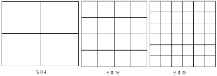
In this section, the parameters of the square grounding grid are calculated. Then the effects of the presence of vertical rods, soil resistivity and depth of grounding grid not only on decreasing grounding resistance but also on the reducing of the earth surface potential, touch voltage and step voltage are investigated. The characteristics of the square grounding grids are: the area is 35.44 m×35.44 m, the radius of grid electrode is 0.005 m, the depth of the grid is 0.5 m, the length of the vertical rod is 2 m, the radius of the vertical rod is 0.0125m, the soil resistivity is 400 ohm.m and the total ground potential rise (GPR) is defined as 1 V. The cases under study are shown in Figure (2), which have the same area and various number of meshes.
Fig - 2: Square grounding grids with different meshes
every case is illustrated in table 1.
Table 1. Number of simulation charges in every case
Case C 4 C 16 C 36 S 4 S 16 S 32
No. of
charges
4397 6785 7165 3597 4985 5845
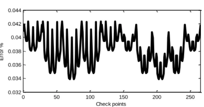
Figure (3) presents the error that calculated on the check points.
Fig- 3: Error along the check points
Figure (4) shows the profile of the earth surface potentials of 36 meshes square grounding grids as an example. Figure (5) shows the effect of the number of meshes on the earth surface potential along the diagonal of the square grounding grids of various number of meshes. It is seen that an increase in the number of meshes makes the curve of earth surface potential much flatter and a reduction in the grid resistance, touch and step voltages.
Fig- 4: Voltage profile along the surface of 36 meshes square grounding grid
Fig - 5: Earth surface potential along the diagonal of the square grounding grids of various number of meshes
0 50 100 150 200 250
0.032 0.034 0.036 0.038 0.04 0.042 0.044 Check points E rr o r % 0 20 40 60 80 0 20 40 60 80 0.4 0.6 0.8 1
Distance along X axis (m) Distance along Y axis (m)
E S P /G P R 0.55 0.6 0.65 0.7 0.75 0.8 0.85 0.9 0.95
0 5 10 15 20 25 30 35 40 45 50
2500 3000 3500 4000 4500 5000 5500 6000 6500
Distance from the center of grid (m) ' Diagonal profile '
E a rt h s u rf a c e p o te n ti a l (V )
Figures (6) and (7) show the effect of increasing the number of mesh on decreasing of the touch voltage and the step voltage of the square grid, respectively.
Fig - 6: Effect of the number of meshes on the touch voltage of the square grounding grids
Fig - 7: Effect of the number of meshes on the step voltage of the square grounding grids
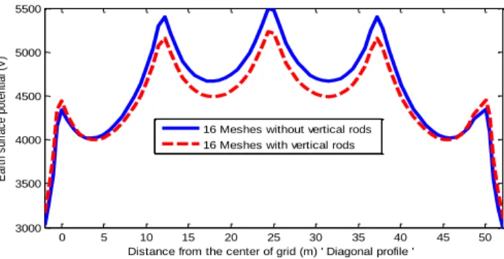
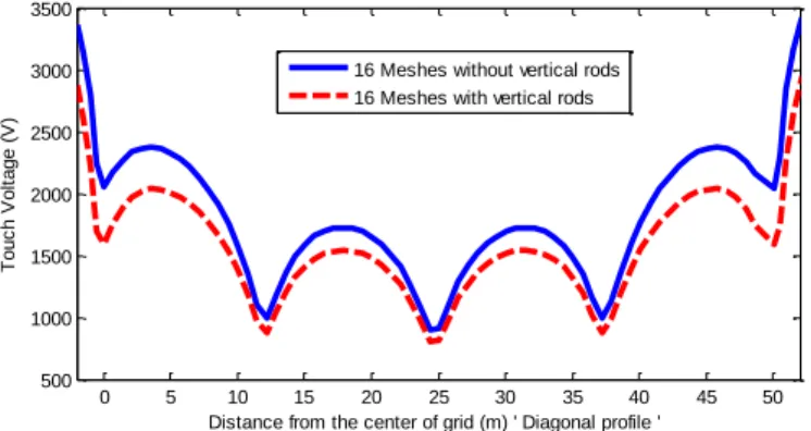
Figure (8) shows the effect of vertical rods on the earth surface potential of the 16 meshes square grounding grid. In this case one rod is erected at each node of the grid. It is seen that the earth surface potential along the diagonal of the grid is slight decreased when the vertical rods are connected to the grid. Figure (9) shows the effect of vertical rods on the touch voltage of the 16 meshes square grounding grid. In this figure the touch voltage is calculated at each point along the diagonal of the grid. Also, it is seen that the touch voltage is slight decreased when the vertical rods are erected at each node of the grid.
Fig- 8: Effect of vertical rods on the earth surface potential of 16 meshes square grounding grid
Figure (10) shows the effect of the soil resistivity values on the earth surface potential of the
0 5 10 15 20 25 30 35 40 45 50
500 1000 1500 2000 2500 3000 3500 4000 4500 T o u c h V o lt a g e ( V )
Distance from the center of grid (m) ' Diagonal profile ' 4 Meshes
16 Meshes 36 Meshes
0 5 10 15 20 25 30 35 40 45 50
0 200 400 600 800 1000 S te p V o lt a g e ( V )
Distance from the center of grid (m) ' Diagonal profile ' 4 Meshes
16 Meses 36 Meshes
0 5 10 15 20 25 30 35 40 45 50
3000 3500 4000 4500 5000 5500 E a rt h s u rf a c e p o te n ti a l (V )
square grounding grid. It is seen that the decrease in the value of the soil resistivity decreases the earth surface potential. Figure (11) proves that the depth of the grid plays an important role in decreasing the earth surface potential.
Fig - 9: Effect of vertical rods on the touch voltage of 16 meshes square grounding grid
Fig- 10: Effect of soil resistivity on the earth surface potential of 16 meshes square grounding grid
Fig- 11: Effect of grid depth on earth surface potential of 16 meshes square grounding grid
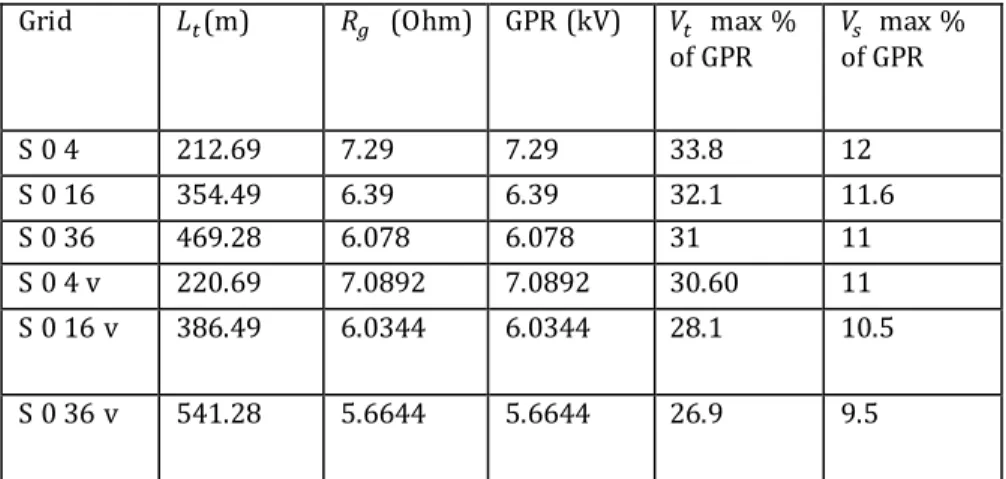
Table 2. explains the effect of the number of meshes on the resistance, ground potential raise, touch voltage, and the step voltage of square grounding grids with and without vertical rods. It is noticed that increasing the number of meshes of grounding grids decreases the values of the grid resistance, ground potential raise, the touch voltage and the step voltage. Also, table 2. contains the total length of the conductors used in each grounding grid, which should be taken into account.
0 5 10 15 20 25 30 35 40 45 50
500 1000 1500 2000 2500 3000 3500 T o u c h V o lt a g e ( V )
Distance from the center of grid (m) ' Diagonal profile ' 16 Meshes without vertical rods 16 Meshes with vertical rods
0 5 10 15 20 25 30 35 40 45 50
102 103 104 105 106 E a rt h s u rf a c e p o te n ti a l V )
Distance from the center of grid (m) ' Diagonal profile ' 16 Meshes at = 40 ohm.m 16 Meshes at = 400 ohm.m 16 Meshes at = 4000 ohm.m 16 Meshes at = 40000 ohm.m
0 5 10 15 20 25 30 35 40 45 50
2500 3000 3500 4000 4500 5000 5500 6000 E a rt h s u rf a c e p o te n ti a l (V )
Table 2.Total conductor length, ground resistance, ground potential raise, touch voltage and step voltage of different square grounding grid cases
Grid 𝐿𝑡(m) 𝑅𝑔 (Ohm) GPR (kV) 𝑉𝑡 max %
of GPR
𝑉𝑠 max % of GPR
S 0 4 212.69 7.29 7.29 33.8 12
S 0 16 354.49 6.39 6.39 32.1 11.6
S 0 36 469.28 6.078 6.078 31 11
S 0 4 v 220.69 7.0892 7.0892 30.60 11
S 0 16 v 386.49 6.0344 6.0344 28.1 10.5
S 0 36 v 541.28 5.6644 5.6644 26.9 9.5
* Where (S04), (S016), and (S036) are the 4, 16, and 36 meshes square grounding grids without vertical rods; and (S04v), (S016v), and (S036v) are the 4,16, and 36 meshes square grounding grids with vertical rods.
Table 3. shows a comparison between the values of the square grounding grid resistances obtained by charge simulation method and those obtained by another formula [1]. It is noticed that there is a good agreement between the results.
Table 3. Grounding grid resistance obtained by CSM and another formula [1]
Grid Dwight[1] Laurent[1] Sverak[1] CSM
S 0 4 5 6.88 6.77 7.29
S 0 16 5 6.02 6.12 6.39
S 0 36 5 5.80 5.70 6.078
S 0 4 v 5 6.812 6.70 7.0892
S 0 16 v 5 6.034 5.93 6.0344
S 0 36 v 5 5.73 5.63 5.6644
2. Circular Grounding Grid
Fig - 12: Circular grounding grids with different meshes
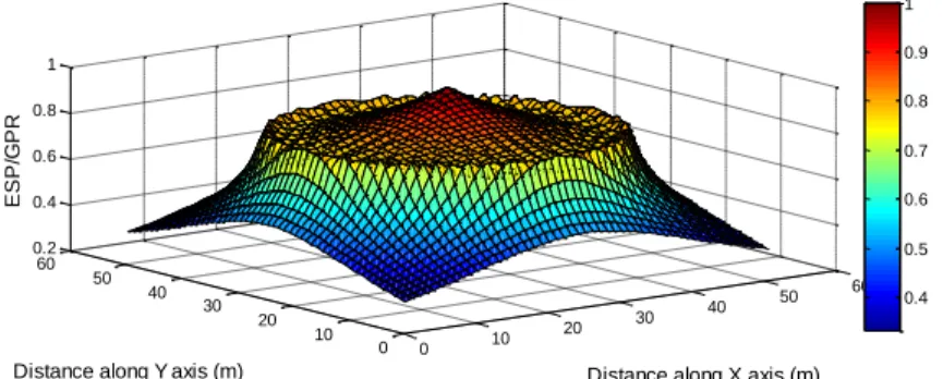
Figure (13) shows the profile of the earth surface potentials of 36 meshes circular grounding grids. Figure (14) shows the effect of the number of meshes on the earth surface potential along the diagonal of the circular grounding grids of various number of meshes. It is seen that an increase in the number of meshes makes the curve of earth surface potential much flatter and a reduction in the grid resistance, touch and step voltages.
Fig - 13: Voltage profile along the surface of 36 meshes circular grounding grid
Fig - 14: Earth surface potential along the diagonal of the circular grounding grids of various number of meshes
Figures (15) and (16) show the effect of increasing the number of mesh on decreasing of the touch voltage and the step voltage of the circular grid, respectively.
Figure (17) shows the effect of vertical rods on the earth surface potential of the 16 meshes circular grounding grid. It is seen that the earth surface potential is slight decreased when the vertical rods are connected to the grid. Figure (18) shows the effect of vertical rods on the touch voltage of the 16 meshes circular grounding grid. Also, it is seen that the touch voltage is slight decreased when the vertical rods are connected to the grid.
Figure (19) shows the effect of the soil resistivity values on the earth surface potential of the
0 10
20 30
40 50
60
0 10 20 30 40 50 60 0.2 0.4 0.6 0.8 1
Distance along X axis (m) Distance along Y axis (m)
E
S
P
/G
P
R
0.4 0.5 0.6 0.7 0.8 0.9 1
-25 -20 -15 -10 -5 0 5 10 15 20 25
3000 3500 4000 4500 5000 5500 6000 6500
Distance from the center of grid (m) ' Diagonal profile '
E
a
rt
h
s
u
rf
a
c
e
p
o
te
n
ti
a
l
(V
)
circular grounding grid. It is seen that the decrease in the value of the soil resistivity decreases the earth surface potential. Figure (20) proves that the depth of the grid plays an important role in decreasing the earth surface potential.
Fig - 15: Effect of the number of meshes on the touch voltage of the circular grounding grids
Fig- 16: Effect of the number of meshes on the step voltage of the circular grounding grids
Fig - 17: Effect of vertical rod on the earth surface potential of 16 meshes circular grounding grid
Fig- 18: Effect of vertical rod on the touch voltage of 16 meshes circular grounding grid
-25 -20 -15 -10 -5 0 5 10 15 20 25
0 1000 2000 3000 4000 5000 T o u c h V o lt a g e ( V )
Distance from the center of grid (m) ' Diagonal profile ' 4 Mesh
16 Mesh 36 Mesh
-25 -20 -15 -10 -5 0 5 10 15 20 25
0 200 400 600 800 1000 S te p V o lt a g e ( V )
Distance from the center of grid (m) ' Diagonal profile ' 4 Mesh
16 Mesh 36 Mesh
-25 -20 -15 -10 -5 0 5 10 15 20 25
2500 3000 3500 4000 4500 5000 5500 6000 E a rt h s u rf a c e p o te n ti a l (V )
Distance from the center of grid (m) ' Diagonal profile ' 16 Meshes without vertical rods 16 Meshes with vertical rods
-25 -20 -15 -10 -5 0 5 10 15 20 25
0 500 1000 1500 2000 2500 3000 3500 T o u c h V o lt a g e ( V )
Fig - 19: Effect of soil resistivity on the earth surface potential of 16 meshes circular grounding grid
Fig - 20: Effect of grid depth on the earth surface potential of 16 meshes circular grounding grid
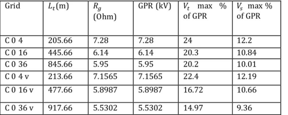
Table 4. explains the effect of the number of meshes on the grid resistance, ground potential raise, touch voltage and the step voltage of circular grounding grids with and without vertical rods. It is noticed that increasing the number of meshes of grounding grids decreases the values of the grid resistance, ground potential raise, the touch voltage and step voltage. Also, table 4. contains the total length of the conductors used in each grounding grid, which should be taken into account.
Table 5. shows a comparison between the values of the circular grounding grid resistances obtained by charge simulation method and those obtained by other formula [1].
Table 4. Total conductor length, ground resistance, ground potential raise, touch voltage and step voltage of different circular grounding grid cases.
Grid 𝐿𝑡(m) 𝑅𝑔
(Ohm)
GPR (kV) 𝑉𝑡 max %
of GPR
𝑉𝑠 max % of GPR
C 0 4 205.66 7.28 7.28 24 12.2
C 0 16 445.66 6.14 6.14 20.3 10.84
C 0 36 845.66 5.95 5.95 20.2 10.01
C 0 4 v 213.66 7.1565 7.1565 22.4 12.19
C 0 16 v 477.66 5.8987 5.8987 16.72 10.66
C 0 36 v 917.66 5.5302 5.5302 14.97 9.36
-25 -20 -15 -10 -5 0 5 10 15 20 25
102 103 104 105 106
Distance from the center of grid (m) ' Diagonal profile '
E
a
rt
h
s
u
rf
a
c
e
p
o
te
n
ti
a
l
(V
)
16 Mesh at = 40 Ohm .m 16 Mesh at = 400 Ohm .m 16 Mesh at = 4000 Ohm .m 16 Mesh at = 40000 Ohm .m
-25 -20 -15 -10 -5 0 5 10 15 20 25
2500 3000 3500 4000 4500 5000 5500 6000
Distance from the center of grid (m) ' Diagonal profile '
E
a
rt
h
s
u
rf
a
c
e
p
o
te
n
ti
a
l
(V
)
*Where (C04), (C016), and (C036) are the 4, 16, and 36 meshes circular grounding grids without vertical rods; and (C04v), (C016v), and (C036v) are the 4, 16, and 36 meshes circular grounding grids with vertical rods.
Table 5. Grounding grid resistance obtained by CSM and other formula [1].
Grid Dwight[1] Laurent[1] Sverak[1] CSM
C 0 4 5 6.94 6.8 7.28
C 0 16 5 5.89 5.79 6.14
C 0 36 5 5.47 5.36 5.95
C 0 4 v 5 6.87 6.76 7.1565
C 0 16 v 5 5.83 5.73 5.8987
C 0 36 v 5 5.43 5.33 5.5302
Comparison Between Circular Grounding Grid And Square Grounding Grid
In this section, a comparison between the results of the square grounding grid and circular grounding grid is done. Firstly, the two types of the ground grids are assumed to be had the same total area enclosed by the ground grid, and secondary, the two types are assumed to be had the same length of the total grounding grid conductor.
Table 6. shows a comparison between the results of both the square grounding grid and circular grounding grid, which have the same total area enclosed by the ground grid.
It is seen that the circular grounding grids give low grounding resistance, step voltage and touch voltage than those of the square grounding grids of the same total area.
Table 6. Comparison between the results of the circular grounding grid and the square grounding grid which have same area
Grid 𝐿𝑡(m) 𝑅𝑔
(Ohm)
GPR (kV) 𝑉𝑡 max
% of GPR
𝑉𝑠 max % of GPR
C 0 4 205.66 7.28 7.28 24 12.2
C 016 445.66 6.14 6.14 20.3 10.84
C 0 36 845.66 5.95 5.95 20.2 10.01
C 0 4 v 213.66 7.1565 7.1565 22.4 12.19
C 0 16 v 477.66 5.8987 5.8987 16.72 10.66
C 0 36 v 917.66 5.5302 5.5302 14.97 9.36
S 0 4 212.69 7.29 7.29 33.8 12
S 0 16 354.49 6.39 6.39 32.1 11.6
S 0 36 469.28 6.078 6.078 31 11
S 0 4 v 220.69 7.0892 7.0892 30.60 11
S 0 16 v 386.49 6.0344 6.0344 28.1 10.5
Secondary, the two types are assumed to be had the same length of the total grounding grid conductor. Table 7. shows a comparison between the results of both the square grounding grid and circular grounding grid, which have the same length of the total grounding grid conductor. It is noticed that it is difficult to explain the effect of the total grounding grid conductor alone without taken into account the area of the grid. In another word, the effect of the non-uniform conductors' distribution within the grid area has an important role in the reducing the grid resistance, and should be studied carefully.
Table 7. Comparison between the results of the circular grounding grid and the square grounding grid, which have the same total length
Case 𝐿𝑡(m) 𝑅𝑔 (Ohm) GPR (kV) 𝑉𝑡 max
% of GPR
𝑉𝑠 max % of GPR
Total area
C 0 4 205.66 7.28 7.28 24 12.2 1256.63
C 016 445.66 6.14 6.14 20.3 10.84 1256.63
C 0 36 845.66 5.95 5.95 20.2 10.01 1256.63
C 0 4 v 213.66 7.1565 7.1565 22.4 12.19 1256.63
C 0 16 v 477.66 5.8987 5.8987 16.72 10.66 1256.63
C 0 36 v 917.66 5.5302 5.5302 14.97 9.36 1256.63
S 0 4 205.66 7.47 7.47 33.7 13 1174.93
S 0 16 445.66 5.39 5.39 35.1 10.6 1986.16
S 0 36 845.66 4.015 4.015 38.3 9.31 3648.709
S 0 4 v 213.66 7.257 7.257 30.33 10 1174.93
S 0 16 v 477.66 5.110 5.110 30.2 8.3 1986.16
S 0 36 v 917.66 3.6758 3.6758 29.2 8.6 3648.709
Validation Of The Simulation Method
In this section the validation of the simulation results is done by comparing some simulation results with the experimental results obtained in this study.
electric resistivity is 33.4 Ωm. The electrolytic resistivity can be changed by changing the salinity of the tap water [13]. A power supply ranges from zero to 380 is used to change applied voltage up to appropriate value. A voltmeter is used to measure the voltage that output from the auto transformer and applied to the model of grounding grid (𝑉𝑠). The magnitude of applied voltage is considered to be constant during the different tests, it is fixed at value equals to 100 volt in all cases. Another voltmeter is used to measure the surface potential (𝑉𝑚), i.e along the diagonal of the grid in this tests. An ammeter is used to measure the current that following through the electrolyte between the model grid and the return electrode. For a scale factor 100:1, variety of grids with outside dimensions of 40 cm 40 cm have been modeled and tested.
Figures (20) and (21) show a comparison between the experimental result and charge simulation method results of a square ground grid of four meshes and a circular ground grid of four meshes, respectively. It is seen that there is a good agreement between the results of the two methods.
Fig - 19: Experimental setup
Table 8. shows a comparison between the values of the grounding grid resistances obtained by experimental method and those obtained by another formula [1] and simulation method. It is noticed that there is an acceptable agreement between the results.
Fig - 20: Earth surface potential of 4 meshes square grounding grid
0 5 10 15 20 25 30 35 40 45 50
0.4 0.5 0.6 0.7 0.8 0.9
E
S
P
/G
P
R
Distance from the center of grid (m) ' Diagonal profile ' 4 Meshes CSM
Fig- 21: Earth surface potential of 4 meshes circular grounding grid
Table 8. Grounding grid resistance obtained by experimental, CSM and another formula [1]
Grid Dwight
[1]
Laurent [1]
Sverak [1]
CSM Experimental
S 0 4 0.417605 0.5745 0.5549 0.6093 0.4761
S 0 16 0.417605 0.51185 0.4921 0.5338 0.4347
C04 0.4175 0.5795 0.56016 0.6102 0.46511
C016 0.4175 0.492444 0.47270 0.5132 0.4166
* Where (S04) and (S016) are the 4, and 16 meshes square grounding grids without vertical rods; and (C04) and (C016) are the 4 and 16 meshes circular grounding grids without vertical rods.
CONCLUSIONS
In this paper, a comparison between two types of grounding grid(square grounding grid and circular grounding grid) is introduced.
The charge simulation method (CSM) and the image method are used in this study. The validation of these methods is satisfied by a comparison between their results and the results obtained by the formula of the IEEE standard. The charge simulation method with the image method give a good agreement with the IEEE standard formula.
A comparison between the results of the circular grounding grid and square grounding grid is done. From the obtained results, it is noticed that the number of meshes plays an important role in reducing the grid resistance, the step voltage and the touch voltage. Also, it is found that there is a slight reduction in the earth surface potential when a set of vertical rods are connected to the grid. Also, increasing the depth of the grounding grid decreases the grid resistance, the step voltage, and the touch voltage.
Also, the circular grounding grid offers good values of the grounding grid parameters (grid resistance, step and touch voltages) compared with the square grounding grid when they have the same total area.
Finally, the results of the experimental model shows that the experimental scale model can be effectively used to study the parameters of the grounding grid design.
-25 -20 -15 -10 -5 0 5 10 15 20 25
0.4 0.45 0.5 0.55 0.6 0.65 0.7 0.75 0.8
E
S
P
/G
P
R
Distance from the center of grid (m) ' Diagonal profile ' 4 Meshes with CSM
REFERENCES
[1] IEEE Guide for safety in AC substation, IEEE std 80 -2000.
[2] J.G Sverak , “Progress in step and touch voltage equations of NSI/IEEE Std. 80,”IEEE Trans .powerDelivery ,Vol. 13 ,No .13, pp .762 -767 ,jul .1999.
[3] J.G Sverak , “ Simplified analysis of electrical gradient above ground grid – I how good is the present IEEE method ? (A Special for WG78.1) , ”IEEE Trans .powerDelivery ,Vol . PAS -103 ,No .1 , pp. 1 – 25 , January 1984.
[4] J. M. Nahman, V. B. Djordjevic, “No uniformity correction factors for maximum mesh and step voltages of ground grids and combined ground electrodes,” IEEE Trans. Power Delivery, Vol. 10, No. 3, pp. 1263-1269, Jul. 1995.
[5] J. M. Nahman, V. B. Djordjevic, “Maximum step voltages of combined grid-multiple rods ground electrodes,” IEEE Trans. Power Delivery, Vol. 13, No. 3, pp. 757-761, Jul. 1998. [6] B. Thapar, V. Gerez, A. Balakrishnan, and D. A. Blank, “Simplified equations for mesh and step
voltages in an AC substation,” IEEE Trans. Power Del., Vol. 6, No. 2, pp. 601-607, Apr. 1991. [7] Hatim Ghazi Zaini, and Sherif S. Ghoneim, “Earth Surface Potential and Grounding Resistance
for Grounding Grid in Two-Layer Model Soil”, 2012 IEEE International Conference on Power System Technology (POWERCON), Oct. 30 2012-Nov. 2 2012.
[8] Sherif Salama, Salah Abdel Sattar and Kamel O. Shoush, “Comparing Charge and Current Simulation Method with Boundary Element Method for Grounding System Calculations in Case of Multi-Layer Soil,” International Journal of Electrical & Computer Sciences IJECS-IJENS , Vol.12, No.04, pp.17-24, August 2012.
[9] Sherif S. M. Ghoneim, Kamel A. Shoush , “Analytical methods for earth surface potential calculation for grounding grids , ” International Journal of Engineering & Computer Science IJECS-IJENS , Vol .13 , No .3 , pp.47- 53 , June 2013 .
[10]Enrique Bendito, Ángeles Carmona, Andrés M. Encinas, and M. José Jiménez, “The Extremal Charges Method in Grounding Grid Design”, IEEE TRANSACTIONS ON POWER DELIVERY, VOL. 19, NO. 1, JANUARY 2004, pp. 118-123.
[11]Sherif S. M. Ghoneim,“Charge and current simulation method with boundary element method for grounding system calculation in case of multi-layer soil”, IOSR Journal of Engineering (IOSRJEN), Vol .3 ,pp.14 -22 , June 2013.
[12]N. H. Malik, “A review of charge simulation method and its application,” IEEE Trans .on Electrical Insulation, Vol. 24, No. 1, pp. 3-20, February 1989.

![Table 5. Grounding grid resistance obtained by CSM and other formula [1].](https://thumb-us.123doks.com/thumbv2/123dok_us/8060186.2134480/11.893.226.663.278.497/table-grounding-grid-resistance-obtained-csm-formula.webp)

