Development Using Hardware
Transactional Memory
Adri`
a Armejach
Facultat d’Inform`
atica de Barcelona
Universitat Polit`
ecnica de Catalunya
A thesis submitted for the degree of
Master in Information Technology
September 2009
Director: Adri´an Cristal Co-Director: Osman Unsal Tutor: Eduard Ayguad´e
Finishing this master thesis ends one chapter of my life and marks the beginning of another.
I would like first to specially thank Marina, for supporting me through the whole process and encourage me to keep learning.
I, of course, would not be here today without the help of my closest people, thanks for being there. My father gets some extra thanks for reading and editing this document.
I must thank all my collages, friends I should say, that made this a wonderful experience. I felt part of the group since the very first day, and they helped me with everything they could. Specially, I would like to thank Saˇsa for being my I-need-help guy, without his help I could not have gotten through; and Ferad for his reviews and nonsense funny laughs.
I also thank my supervisors and tutor, for bringing me this opportu-nity and helping me with their experience.
1 Introduction 1
1.1 Context . . . 1
1.1.1 Why is Parallel Programming Difficult? . . . 2
1.1.2 Transactional Memory . . . 3 1.2 Project Objectives . . . 4 1.3 Project Description . . . 5 1.4 Contributions . . . 7 1.5 Organization . . . 7 2 Transactional Memory 9 2.1 Transactional Memory Basics . . . 9
2.2 Transactional Memory System Taxonomy . . . 11
2.2.1 Eager versus Lazy Data Versioning . . . 11
2.2.2 Optimistic versus Pessimistic Conflict Detection . . . 12
2.2.3 Synergistic Combinations . . . 14
2.3 Software versus Hardware . . . 14
3 Initial Study 15 3.1 Scalable-TCC - The Protocol . . . 15
3.1.1 Protocol Overview . . . 15
3.1.2 Protocol Details . . . 17
3.1.3 Commit Example . . . 18
3.1.4 Parallel Commit Example . . . 21
3.2 The M5 Simulator . . . 23
4 Related Work 26
5 Architectural Details 28
5.1 Architecture Overview . . . 28
5.2 The Processor . . . 28
5.3 The Directory . . . 31
5.4 The Interconnection Network . . . 32
6 Cache with Directory Module 34 6.1 Cache State Transitions . . . 34
6.2 Configuration and Functionalities . . . 36
6.3 Diagrams . . . 40
6.4 Statistics . . . 41
6.4.1 Cache and Main Memory Statistics . . . 42
6.4.2 Directory Statistics . . . 43
6.5 Programming Methodology and Testing . . . 43
6.6 Unit Test and Statistics Output Example . . . 44
7 The HTM Module 48 7.1 HTM State Transitions . . . 48 7.2 Functionalities . . . 50 7.3 Diagrams . . . 53 7.4 Statistics . . . 54 7.4.1 Transaction Statistics . . . 54 7.4.2 Global HTM Statistics . . . 55
7.5 Unit Test and Statistics Output Example . . . 57
8 Merging within M5 - The Process 63 8.1 Running M5 in Full-System Mode . . . 63
8.2 Modifications and Additions . . . 64
9 Evaluation 68
9.1 System Configuration . . . 68
9.2 Methodology . . . 69
9.2.1 The STAMP Applications . . . 69
9.2.2 Modifications Required . . . 71
9.3 Results and Discussion . . . 72
10 Project Analysis 81 10.1 Project Planning . . . 81 10.1.1 Work Package 1 . . . 82 10.1.2 Work Package 2 . . . 83 10.1.3 Work Package 3 . . . 86 10.2 Project Cost . . . 88 10.2.1 Human Resources . . . 88 10.2.2 Hardware Resources . . . 88 10.2.3 Software Resources . . . 89 10.2.4 Total Cost . . . 90 10.3 Achieved Objectives . . . 90 10.4 Future Work . . . 91 10.5 Personal Conclusions . . . 91 Bibliography 96
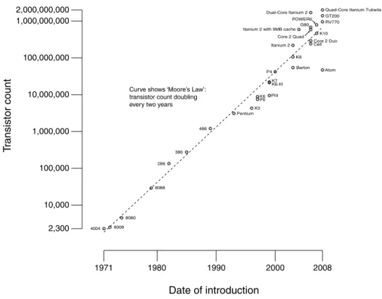
1.1 Curve showing CPU transistors count 1971-2008. . . 2
2.1 Group of instructions representing a transaction. . . 10
2.2 Deadlock situation using eager data versioning policy. . . 12
2.3 Pessimistic and optimistic conflict detection behaviors. . . 13
3.1 System organization schema. . . 16
3.2 Scalable-TCC commit execution example. . . 19
3.3 Two scenarios attempting to commit two transactions in parallel. 22 5.1 Processor details. . . 30
5.2 The directory structure. . . 31
5.3 Interconnection Network distribution, node organized. . . 33
6.1 Cache transitions state diagram. . . 35
6.2 2-Way associative cache fill. . . 37
6.3 Inheritance and relation diagrams from cache and main memory point of view. . . 41
6.4 Struct that handles the statistics at cache and main memory levels. 42 6.5 Struct that handles the statistics for the directories. . . 43
6.6 Unit test example using QuickTest. . . 44
6.7 Unit test example, cache hierarchy simplest. . . 46
6.8 Cache statistics results of executing the cache hierarchy simplest test. . . 47
7.2 Relation diagrams from FakeCPU and HTM interface point of view. 53
7.3 Statistics gathered at transaction level. . . 55
7.4 Statistics gathered at HTM level. . . 56
7.5 HTM module unit test example, called: simple write back trans-actional. . . 59
7.6 Global HTM statistics. . . 62
8.1 Bootscript to launch genome test with 8 processors. . . 64
8.2 XOR-based HTM instructions. . . 65
9.1 New directives added to the STAMP tests. . . 71
9.2 Scalable TCC HTM execution time (1/2) . . . 79
9.3 Scalable TCC HTM execution time (2/2) . . . 80
10.1 Work package 1 Gantt diagram, initial plan. . . 82
10.2 Work package 2 Gantt diagram, first sub package, initial plan. . . 83
10.3 Work package 2 Gantt diagram, second sub package, initial plan. . 84
10.4 Work package 2 Gantt diagram, third sub package, initial plan. . . 85
3.1 The coherence messages used to implement Scalable-TCC protocol. 18
7.1 Transaction stats information, some irrelevant fields were dropped. 61
9.1 Parameters for simulated architecture. . . 68
9.2 The applications of the STAMP suite. . . 70
9.3 HTM Execution Statistics (1/2). . . 75
9.4 HTM Execution Statistics (2/2). . . 76
10.1 Total human resources costs. . . 88
10.2 Total hardware resources costs. . . 89
Introduction
This thesis has been developed in the joint center held by Barcelona Supercomput-ing Center (BSC) in collaboration with Microsoft Research (MSR). The Center focuses on the design of future microprocessors and software for the mobile and desktop market segments basis (1).
The following sections of this chapter discuss the context and motivations of this thesis, along with its scope, main objectives and contributions.
1.1
Context
During the last decades the number of transistors in a single chip has increased exponentially, from the first home computers that had a few thousands of transis-tors (∼6.000) to today’s designs that involve hundreds of millions (∼700.000.000) (6). Given this ever-increasing transistor densities (see Figure1.1), and mainly in response to the problems of incrementing performance in single-threaded proces-sors that computer architects faced over the last years (e.g., undesirable levels of power consumption because of high clock frequencies (15)), manufacturers have shifted to multiprocessor designs instead. Large-scale multiprocessors with more than 16 cores on a single board or even on a single chip will soon be available. This is achieved by using a simpler and smaller core processor design and replicating it many times, reducing power requirements and making thread-level parallelism the new challenge to achieve high performance.
Figure 1.1: Curve showing CPU transistors count 1971-2008.
The advent of chip multiprocessors (CMPs) has moved parallel programming from the domain of high performance computing to the mainstream. Now, soft-ware developers have the difficult task to write parallel programs to take advan-tage of multiprocessor hardware architectures.
1.1.1
Why is Parallel Programming Difficult?
Parallel programs are more difficult to write than sequential ones, concurrency introduces several new classes of potential software bugs, of which race condi-tions (e.g., data dependencies) are the most common ones (25). To take advan-tage of thread-level parallelism involves creating several parallel tasks that need to synchronize and communicate to each other. Today’s programming models commonly achieve this via lock-based approaches, in this parallel programming technique, locks are used to provide mutual exclusion for shared memory accesses that are used for communication among parallel tasks.
Unfortunately, when using locks, programmers must pick between two unde-sirable choices:
• Use coarse-grain locks, where large regions of code are indicated as critical regions. This makes the task of adding coarse-grain locks to a program quite straightforward, but introduces unnecessary serialization that degrades sys-tem performance.
• On the other side, fine-grain locks cause critical sections of minimum size. Smaller critical sections permit greater concurrency, and thus scalability. Anyway, this schema leads to higher complexity, and makes it more likely to have problems such as deadlock.
There are many other problems related with locks, some of the most important are: priority inversion, convoying and debugging. The first one prevents high priority threads to be executed if a low priority one is holding the common lock, while in convoying all the other threads of the system have to wait if the thread holding the lock gets de-scheduled due to an interrupt or a page fault; finally, lock-based programs are difficult to debug, since bugs are very hard to reproduce themselves (8).
1.1.2
Transactional Memory
To address the need for a simpler parallel programming model, Transactional Memory (TM) has been developed and promises good parallel performance with easy-to-write parallel code (22;25).
Unlike lock-based approaches, with TM, programmers do not need to explic-itly specify and manage the synchronization among threads; however, program-mers simply mark code segments as transactions that should execute atomically
and in isolation with respect to other code, and the TM system manages the concurrency control for them. It is easier for programmers to reason about the execution of a transactional program since the transactions are executed in logical sequential order according to a serializable schedule model.
TM allows non-blocking synchronization with coarse-grained code, deadlock and livelock freedom guarantees. Non-blocking synchronization is achieved by
executing the transactions optimistically (in parallel), while still guaranteeing exactly-once execution as if these were ran in isolation and committed in a serial order. If any conflicts are detected during the execution, some of these transac-tions will be aborted to maintain system consistency.
TM can be implemented either in software (STM) or hardware (HTM). STMs are more flexible but suffer from serious performance overheads whereas HTMs are faster but limited due to hardware space constrains, even though this space limitations can be handled using virtualization or other mechanisms (30).
As more processing elements become available, programmers should be able to use the same programming model for setups of varying scales. Hence, TM is of long-term interest if it scales to large-scale multiprocessors properly.
1.2
Project Objectives
In the previous section, we stated several problems regarding the actual program-ming models when developing parallel applications, and how new approaches like TM are coming up to solve those problems. The main motivation for researching new ways to face parallel programming issues is that manufacturers are turning to CMPs in detriment of single-threaded processors as a realistic path towards scalable performance for server, embedded, desktop and even notebook platforms (16;26).
This project aims two main goals. The first one is to develop a Hardware Transactional Memory (HTM) module based on an already existing protocol, and integrate it into a full-system simulator. Evaluate its performance using realistic benchmarking tools and extract conclusions about its scalability and performance.
The second one is to provide a tool to experience with its many configurable parameters, to see how different setups of the components (e.g., size or associa-tivity of the caches) affect the performance of this kind of systems and to be able to detect its associated pathologies or if any bottleneck exist. Furthermore, it can also be used to compare new approaches that are under development (35) or that can be implemented in a near future in the Center against an existing state-of-the-art proposal.
1.3
Project Description
The protocol chosen to implement the HTM module is the first non-blocking TM implementation that targets distributed shared memory (DSM) systems, and uses directory-based mechanisms to ensure coherence and consistency. By targeting DSM-like systems we are focusing in the domain of high performance computing sector. This protocol is called Scalable Transactional Coherence and Consistency (Scalable-TCC) (19).
With regard to the simulator, we used The M5 Simulator: a modular platform for computer system architecture research, with system-level architecture as well as processor micro-architecture basis (12). It supports multiple Instruction Set Architectures (ISAs) such as Alpha, SPARC, MIPS, and ARM, with X86 sup-port in progress. However, full-system capability is only available in Alpha and SPARC. For our project we will use Alpha architecture since it is the only one that can boot Linux 2.4/2.6, and we are more familiar with this OS than others. In order to achieve our objectives the whole project workload has been split in three work packages:
• Introduction and generic modifications to The M5 Simulator.
• Scalable-TCC HTM module.
• Merge Scalable-TCC HTM module into The M5 Simulator.
In thefirst package, once the system was set and running, we learned about The M5 Simulator structure and its tools. Moreover, some generic modifications have been done to the simulator that will be useful in the future when merging the Scalable-TCC HTM module into it (e.g., extend the ISA to support instruction to begin and commit a transaction).
The second package has the largest volume of work. First of all, a con-siderable amount of time was spent on reading about TM and directory-based protocols, to have a general knowledge to be able to analyze properly the descrip-tion proposed on the Scalable-TCC paper. Afterwards, before starting to specify and implement the HTM module, some decisions about the cache hierarchy setup and how to implement DSM were made. The implementation of the HTM module was split into two different and isolated sub-projects:
• A cache-simulator with directory that fits to the Scalable-TCC directory-based protocol demands. For this module an already existing cache-simulator for MESI protocol was at our disposal. Nevertheless, Scalable-TCC proto-col has been proven to behave quite different than common MESI/MOESI like protocols, besides the fact that it was not prepared for DSM-like sys-tems nor for a directory-based protocol. Therefore, all the functionalities have been written from scratch.
This module allows the creation of a cache hierarchy (L1, L2, etc.), it also handles main memory using DSM schema and the directory structures. Statistics are incorporated at cache level (i.e., for every cache level), at main memory, and at directory level. Tracking events such as: hits, misses and ticks spent, amongst others; that occur on these mentioned structures.
• The HTM module will interact with the previous one to define the desired memory hierarchy for each node of the system. The module defines the concept of transaction and stores the necessary information such as the transaction state and the transaction identifier. The interface of the HTM is also defined here, so here are defined the behaviors, for example, of the
begin and commit transaction instructions, among others.
Since we want a powerful statistics system, there will be statistics at trans-action and at HTM level too; regarding to the number of memory accesses,
begin instructions executed, etc.
By splitting the work in two smaller sub-projects we can trace errors easier than having a larger single project. For this reason, each subproject has been checked separately using unit tests to verify its functionalities, and using some stress tests afterwards, to ensure a higher degree of correctness before starting the last work package.
In the third package of this project we merged the HTM module into The M5 Simulator. During this process some modifications on both sides, the HTM module and the simulator were really necessary. For example, in the simulator side, we had to declare the memory hierarchy and its parameters using our im-plementation. Some more complex modifications regarding fault tolerance and switching from user-mode to kernel-mode (and vice versa) were also necessary.
After checking that the integration was working as expected, we started with the testing phase using a couple of basic tests (e.g., incrementing a shared counter using transactions). Once those test were passed correctly, a set of synthetic benchmarks that are intended to represent real applications that cover a wide range of transactional scenarios (17), were used to evaluate performance and scalability of the system.
1.4
Contributions
Basically, this thesis presents the implementation and evaluation of a hardware transactional memory system. Its major contributions are:
• Propose an implementation of a scalable design for TM that is non-blocking and is tuned for continuous transactional execution.
• Provide a memory system, that allows for a configurable number of cache entries, associativity, cache-line size, and all the access timings in the mem-ory hierarchy.
• Provide a powerful statistics system to extract conclusions about the trans-actional executions. In particular, we have stats for every level of cache, main memory bank, directory, transaction and at global HTM level.
• Demonstrate that the proposed TM implementation scales efficiently to 32 processors in a DSM system for a wide range of transactional scenarios.
1.5
Organization
After introducing the context, and state the objectives and contributions of the project, in this section, we explain the structure of the document with a brief description of each chapter.
The second chapter introduces basic concepts about transactional memory, discussing different possible design approaches, stating its advantages and disad-vantages.
The third chapter explains in detail the protocol that our HTM simulator will use and the configuration choices done at this moment in the simulator side.
The fourth chapter presents the related work, where we talk about some of the most relevant proposals regarding transactional memory.
The fifth chapter introduces the architecture details that our proposal will use, at processor, caches, directory and interconnection network level.
The sixth chapter presents the cache with directory module, with a general detailed explanation, the functionalities and configuration possibilities it imple-ments, the available statistics and a unit test example showing its execution statistics output.
The seventh chapter follows the same layout than the previous one, but ex-plaining the HTM module.
The eighth chapter explains the merging process of the HTM module and The M5 simulator, along with the modifications required in the simulator side and the problems encountered.
The ninth is the evaluation chapter, where we introduce the system configu-ration used to run the tests, the methodology, and finally we present and discuss our results.
The tenth chapter explains the initial planning and its modifications, the project costs, achieved objectives, exposes future lines of work and personal con-clusions.
Transactional Memory
In this chapter we introduce some basic concepts about Transactional Memory (TM), like its properties, along with the mechanisms and policies used to guar-antee those properties. We also discuss the advantages and disadvantages of Hardware and Software based systems.
2.1
Transactional Memory Basics
Using conventional multi-threaded programming on shared memory machines, programmers need to manually manage the synchronization among threads when they use locks. For example, they must select the lock granularity, create an association between shared data and locks, and manage lock contention. In other words, with locks, programmers not only need to declare where synchronization is used, they must also implement how synchronization will occur.
In contrast, with Transactional Memory (TM), programmers simply declare where synchronization occurs, and the TM system will handle the implementation properly. In more detail, with TM, programmers indicate that a code segment should be executed as a transaction by placing that group of instructions inside an atomic block (28) as shown in Figure 2.1.
It is the responsibility of the TM system to guarantee that the transactions have the following properties: atomicity, isolation, and serializability. Firstly,
atomic {
if ( foo != NULL ) a.bar(); b++;
}
Figure 2.1: Group of instructions representing a transaction.
must be executed. Secondly, having isolation means that none of the intermedi-ate stintermedi-ate of a transaction is visible outside of the transaction (i.e., any memory update is visible to other threads during the execution of a transaction). Fi-nally, serializability requires that the execution order of concurrent transactions is equivalent to some sequential execution order of the same transactions (24).
The way that TM systems achieve good parallel performance is by providing optimistic concurrency control (19), where a transaction runs without acquiring locks, optimistically assuming that no other transaction operates concurrently on the same data. When the TM system executes the body of an atomic block, it is done speculatively (hence the name optimistic). While the body is executed, any memory addresses that are read are added to a read set, and the ones that are written are added to a write set. Finally, at the end of the atomic block, the TM system ends, or commits, the transaction.
To verify that the speculative execution of the transaction is valid, the TM system compares the read and write sets of all concurrent transactions. This allows to perform fine-grain read-write and write-write conflict detection (i.e., to know the exact conflicting address). If no conflicts are detected, the transaction commits successfully, otherwise it is aborted, and the execution is rolled back to the beginning of the atomic block and retried.
The key idea of TM is that because of their atomicity, isolation, and serial-izability properties, transactions can be used to build parallel programs. Using large atomic blocks simplifies parallel programming because it provides ease-of-use and good performance. First, like coarse-grain locks, it is relatively easy to reason about the correctness of transactions. Second, to achieve a performance comparable to that of fine-grain locks, the programmer does not have to do any extra work because the TM system will handle that task automatically for him (24).
2.2
Transactional Memory System Taxonomy
Like in database systems, there are a variety of ways to provide transactional properties of atomicity and isolation. There are three categories that can be used to classify TM systems: the data versioning mechanism, the conflict detec-tion policy, and the approach used for implementation, being hardware-based orsoftware-based (24;27).
2.2.1
Eager versus Lazy Data Versioning
Transactional systems must be able, at least, to deal with two versions of the same logical data. An updated version and an old version, just in case the transaction fails to commit, so the old version can be used to roll back. Updates to memory addresses, when a write is executed by a transaction can be handled either eagerly or lazily (27).
In lazy data versioning, updates to memory are done at commit time. New values are saved in a per transaction store buffer, while old values remain in place. This grantsisolation, because all the speculative updates are not visible by other threads until the transaction commits. On the other side, eager data versioning
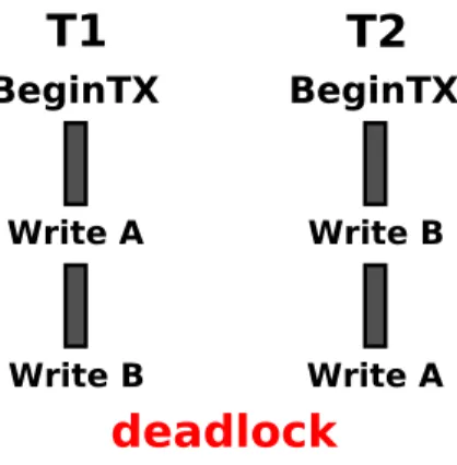
applies memory changes immediately and the old values are stored in an undo log. If the transaction aborts, the undo log is used to restore memory changes. Note that in order to grant isolation in eager TM systems, transactionally modified variables must be locked, and therefore they cannot be accessed until the owner either commits or aborts the transaction. This can derive into a classic deadlock situation, as shown in Figure 2.2, where transaction T1 has acquired the lock for memory address A and is waiting to acquire the lock of memory address B, and
T2 has acquired the lock for address B and is waiting to acquire A’s address lock. Therefore, acontention management mechanism is required, and when detecting a potential deadlock cycle it will break it by choosing a victim to abort and
roll-back.
Each data versioning, eager and lazy, has its own advantages and disadvan-tages. Eager versioning systems have a higher overhead on transaction abort because they have to restore the memory changes. In contrast, lazy versioning aborts have smaller overhead since no speculative updates were applied to main
T1
T2
BeginTX BeginTX Write A Write A Write B Write Bdeadlock
Figure 2.2: Deadlock situation in a system running with an eager data versioning policy. Both transactions are waiting for the other one to free a locked address.
memory. However, lazy policies have performance penalty at commit time, when all transactional updates become visible.
2.2.2
Optimistic versus Pessimistic Conflict Detection
Conflict detection can be performed either taking an optimistic or a pessimistic approach. Systems with pessimistic conflict detection notice possible data de-pendency violations as soon as possible, checking for conflicts on each memory access during transaction execution. On the other hand, optimistic conflict de-tection assumes that a transaction is going to commit successfully and waits until the transaction finishes its execution to detect the conflicts.
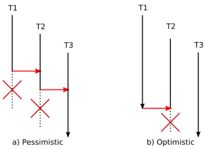
Conflict management can substantially affect system performance, we illus-trate the problem in Figure 2.3 (this example is inspired from (34)). Pessimistic conflict detection, Figure 2.3-a, attempts to minimize the amount of wasted work in the system. Transaction T1 conflicts with T2 and is stalled (waiting for T2 to finish). Then,T2 conflicts later on its execution withT3 and gets stalled too. Note that T1 now has to wait until T3 (and then T2) either aborts or commits, even though it does not conflict with T3 at all. Most systems that use this pessimistic approach suffer from these so-called cascading waits (14), where a transaction is stalled waiting for transactions to finish even if there are no conflicts between them.
T1 T2 T3 a) Pessimistic b) Optimistic T1 T2 T3
Figure 2.3: Pessimistic and optimistic conflict detection behaviors.
Figure2.3-b, shows the same execution with optimistic conflict detection. In this case, all the transactions are executing until one reaches its commit point. As we can see, transaction T1 attempts to commit, and therefore transaction T2 aborts. Then, T3 can also commit without conflicts.
As we can see with this example, attempts by pessimistic systems to reduce wasted work are not always successful. In Figure 2.3-a, for instance, the systems stallsT1, and since it does not eventually abort, the work that was avoided would have been useful. This happens due to a limitation in pessimistic systems; it addresses potential conflicts, caused by an offending access to a shared location, at this point they have to speculate which transaction is more likely to commit (and which should be aborted), but the system at this time does not have all the necessary information to make the optimal decision and the prediction is sometimes wrong. On the other hand, optimistic conflict detection deals with conflicts that are unavoidable in order to allow a transaction to commit.
Previous research claims thatoptimistic conflict detection allows for more par-allelism (14;24;31), delaying conflict detection at commit time avoids speculative decisions of which is the best transaction to abort, simplifies the system, and also results in higher performance due to a larger number of transactions committing. Furthermore, optimistic conflict detection guarantees forward progress, processor instructions are guaranteed to complete properly.
2.2.3
Synergistic Combinations
We introduced two ways to deal with data versioning (eagerly or lazily) and two ways to treat conflict detection (pessimistically or optimistically). Intuitively, eager data versioning, where memory updates are done while the transaction is executed, is commonly used with pessimistic conflict detection to ensure that only one transaction has exclusive access to write a new version of a given address. On the other hand, lazy data versioning is usually combined with optimistic conflict detection, doing both tasks (conflict detection and memory updates) at commit time.
However, these are not the only two alternatives. Some of the first TM pro-posals provide lazy versioning with pessimistic conflict detection. On the other hand, recent research tries to split the monolithic task of conflict detection and adopt an approach that detects conflicts while the transaction is still active (i.e., at every memory access), but resolves them when the transaction is ready to commit (35).
2.3
Software versus Hardware
Software Transactional Memory (STM) systems are not expensive to build, are very flexible about implementing different policies and do not suffer from buffer-ing overflow constrains. However, software is not as fast as dedicated hardware because of the greater overheads it has on every memory access, where data structures must be maintained and eventually queried to perform conflict detec-tion. In contrast, Hardware Transactional Memory (HTM) systems offer higher performance because no software annotations are required on memory accesses. However, they can encounter difficulties when transactionally-accessed lines over-flow the capacity of the cache.
Another approach for TM are hybrid systems, like (18). These systems try to either address the challenges of HTM systems switching to an STM system when, for example, hardware resources become exhausted, or even introduce hardware changes to gain performance and address bottlenecks of software transactions.
Initial Study
This chapter focuses on the explanation of the HTM protocol and the main characteristics and configuration choices of the M5 simulator.
3.1
Scalable-TCC - The Protocol
This section covers the protocol explanation. Firstly, an overview and some protocol details are exposed. Then, we show two detailed examples that clarify the protocol operation process.
3.1.1
Protocol Overview
Scalable-TCC is a non-blocking implementation of TM that is tuned for contin-uous use of transactions within parallel programs (19). By adopting continuous transactions we can implement a single coherence protocol, we don’t need to dis-tinguish transactional accesses from non-transactional since all memory accesses will be considered transactional. This fact makes the consistency model much simpler and easier to understand.
The “illusion” of executing always-in-transaction does not need any code mod-ification at all, it is completely transparent to the programmers point of view and it is handled at runtime by the HTM. When a memory access is executed outside a real or explicit transaction (i.e., outside an atomic block, see Figure 2.1), it is detected and the system immediately starts a forced or implicit transaction
(assuming that no other implicit transaction is running). If the system is ex-ecuting an implicit transaction and an explicit transaction is going to start, it will automatically commit the first one in order to guarantee the properties of atomicity and isolation of explicit transactions. Note that implicit transactions can be committed at any point in time without altering the correctness of the execution whatsoever.
One of the best properties of this protocol is its non-blocking implementation. This is achieved by detecting conflicts only when a transaction is ready to com-mit; hence, using optimistic conflict detection, running the transaction without acquiring locks, optimistically assuming that no other transaction operates con-currently on the same data. If conflicts between transactions are detected, the non-committing transactions abort, their local updates are rolled-back, and they are re-executed. Scalable-TCC also uses lazy data versioning which allows trans-actional data into the system memory only when a transaction commits. Having lazy data versioning guarantees deadlock and livelock freedom without interven-tion from user-level conteninterven-tion managers as we meninterven-tioned in Secinterven-tion 2.2.1.
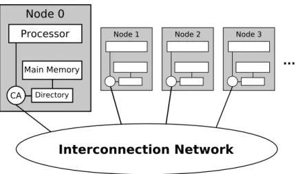
Interconnection Network Processor Main Memory Directory CA ... Node 0
Node 1 Node 2 Node 3
Figure 3.1: System organization schema; CA states forCommunication Assistant.
Figure 3.1 shows the system organization. We use distributed shared mem-ory (DSM) with directmem-ory-based coherence. Using DSM means that the memmem-ory address space is split amongst the different nodes of the system, so each memory address belongs to one node. In directory-based coherence, information about the addresses being shared (e.g., a sharers list) is placed in the directories that
maintain the coherence between caches. Note that since DSM is used, each di-rectory will hold information of the addresses belonging to its own node. The directory acts like a filter through which the processor must ask permission to load an address from main memory to its caches. We will show details about the directory behavior later in this section; see examples 3.1.3 and 3.1.4.
3.1.2
Protocol Details
The key idea that allows the protocol to achieve a high degree of concurrency is the possibility to commit two or more transactions in parallel if they involve data from separate directories.
First, transactions are executed, execution phase, during the execution all memory accesses are not visible to the rest of the system. This means that: a) read and written addresses are added to per-transaction private structures called
read-set and write-set respectively; b) written data is buffered locally in private caches.
Then, the transaction is ready to start the commit process, which has two phases:
• Validation Phase: The system ensures that the transaction is serially valid. To check this condition the system asks,only the directories involved in the write-set and the read-set, if there are younger transactions waiting to commit on these directories. If there are no younger transactions wait-ing, this phase completes and the transaction cannot be aborted by other transactions anymore. Note that two transactions with a disjoint set of committing directories can go through the commit process completely in parallel.
• Commit Phase: After validation phase, the transaction makes its write-state visible to the rest of the system and the commit process finishes.
Directories are used to track processors that may have speculatively read shared data. When a processor is in its validation phase, it acquires a transac-tional ID (TID) and does not proceed to its commit phase until it is guaranteed that no other processor can abort it, then sends its commit addresses only to the
directories responsible for data written by the transaction. The directories gener-ate invalidation messages to processors that were marked as having read what is now invalid data. Processors receiving invalidation messages then use their own tracking facilities to determine whether to abort or just invalidate the cache-line if it was not read in the current transaction. Note that we use the term cache-line
here, this is because our HTM implementation works with cache-line granularity, all the addresses present in read or write sets and in the directories are cache-line addresses.
Each directory tracks the TID currently allowed to commit in the Now Ser-vicing TID (NSTID) register. When a transaction has nothing to send to a particular directory by the time it is ready to commit, it informs the directory by sending a Skip message that includes its TID, so that the directory knows not to wait for that particular transaction. A complete list of the coherence messages used in our Scalable-TCC-like implementation is shown in Table 3.1.
Message Description
Add Sharer Load a cache-line
TID Request Request a transactional identifier
Skip Instructs a directory to skip a given TID NSTID Probe Probes for the Now Servicing TID register Commit Instructs a directory to commit marked lines Invalidate Instructs a processor to treat an invalidation Abort Instructs a directory to abort a given TID Mark Marks a line intended to be committed
Data Request Instructs a processor to flush a given cache-line to memory Write Back Write back a committed cache-line
Table 3.1: The coherence messages used to implement Scalable-TCC protocol.
3.1.3
Commit Example
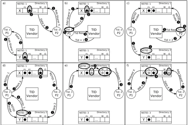
The following example, see Figure3.2, attempts to illustrate all the possible situ-ations that may occur during the execution phase and during a successful commit
process between two processors. In the example, inspired from (19), a transaction in P1 successfully commits with one directory while a second transaction in P2
aborts and restarts.
During the explanation of the example we use the coherence messages listed in Table3.1. Changes in the state are circled and events numbered to show order, meaning all events numbered 1ycan occur at the same time and an event labeled
y
2 can only occur after all events labeled 1yare done.
TID Vendor NSTID: 1 ... Directory 1 P1 P2 M O NSTID: 1 ... Directory 2 P1 P2 M O P1 P2 Tid: x Tid: x a) TID Vendor NSTID: 1 ... Directory 1 P1 P2 M O NSTID: 1 ... Directory 2 P1 P2 M O P1 P2 Tid: 1 Tid: x b) TID Vendor NSTID: 1 ... Directory 1 P1 P2 M O NSTID: 2 ... Directory 2 P1 P2 M O P1 P2 Tid: 1 Tid: 2 c) TID Vendor NSTID: 1 ... Directory 1 P1 P2 M O NSTID: 3 ... Directory 2 P1 P2 M O P1 P2 Tid: 1 Tid: 2 d) TID Vendor NSTID: 2 ... Directory 1 P1 P2 M O NSTID: 3 ... Directory 2 P1 P2 M O P1 P2 Tid: 1 Tid: 2 e) TID Vendor NSTID: 2 ... Directory 1 P1 P2 M O NSTID: 3 ... Directory 2 P1 P2 M O P1 P2 Tid: 1 Tid: 2 f) 1Add Sharer Y Y X Data Y 2 Add Sharer X 1 Data X 2 2 2 X Y X Y Add Sharer X 1 Data X 2 2 Tid Req3 Tid = 14 5 NSTIDProbe 1 Skip 1 1 1Tid Req NSTID Probe 1 Tid = 22 2 3 Y X NSTID Probe NSTID: 1 Mark X NSTID: 1 NSTID: 3 Skip 2 1 1 1 2 2 3 3 4 X X Y Y Commit 1 2 Invalidate X 3 Add Sharer X Request X WB X Data X 1 2 3 4 4 5
Figure 3.2: Scalable-TCC commit execution example.
In part a, processorsP1 and P2 each load a cache-line using theAdd Sharer
message 1y, and are marked as sharers byDirectory 2 andDirectory 1
respec-tively. Note that now both processors are in the execution phase at the same time.
In this example, both processors write to data tracked by Directory 1, but this information is not communicated to the directory until the commit phase. In part b, processor P1 loads another cache-line from Directory 1 and then starts
the commit process, thus it starts the validation phase. Then, it first sends a
T ID Request message to the TID Vendor 3y, which responds with T ID 1 4yand
processor P1 records it 5y.
In part c,P1, that is still in its validation phase, communicates withDirectory 1, the only directory it wants to write to. First, it probes this directory for its
Now Servicing TID (NSTID) register using an N ST ID P robe message 1y. In
parallel, P1 sends to Directory 2 a Skip message since Directory 2 is not in the write-set, causing it to increase its NSTID to 2 2y. Meanwhile, P2 has also
started the commit process (validation phase). It requests a TID 1y, but can also
start probing forDirectory 1 NSTID register 1y— probing does not require the
processor to have acquired a TID. P2 receivesT ID 2 2yand records it internally
y
3.
In part d, both P1 and P2 receive answers to their probing messages, and P2
also sends aSkipmessage toDirectory 2 1ythat updates its NSTID register to 3
y
2. P2cannot finish its validation phase because the TID answer it received is lower
than its own TID. On the other hand, P1’s TID is equal to the NSTID register
from Directory 1, thus it can send commit-addresses using M ark messages
to that directory. P1 sends a M ark message 2y, and line X becomes marked
(M) as part of the committing transaction’s write-set 3y. Mark messages allow
transactions to pre-commit addresses to the subset of directories that are ready to service the transaction. In order to finish the validation phase, P1 has to be sure that no other transactions with a lower TID can violate it. This is done by checking that every directory in its read-set (1 and 2) has finished servicing younger transactions. Since it has already marked lines inDirectory 1, it can be certain that all transactions with lower TID’s have been serviced by this directory. However,Directory 2 needs to be probed 3y. P1 receives NSTID 3 as answer 4y,
this means that it can be certain that all transactions younger than TID 3 have been already serviced by Directory 2. Thus, P1 cannot be aborted by commits to any directory and finishes the validation phase.
In part e,P1 sends a Commit message 1y, which causes all marked (M) lines
to become owned (O) 2y. Each marked line that transitions to owned generates
invalidations that are sent to all sharers of that line 3y, except the committing
the line from its private caches and aborts because its current transaction had read it. Note that during the whole commit process no data is communicated between nodes and directories, only addresses, making the process quite cheap in time basis.
In part f, P2, that has to re-execute the transaction, attempts to load an owned line 1y, this causes the directory to send a data request to the owner 2y;
the owner then writes back the cache-line and invalidates the line in its private caches 3y. When receiving the data, the directory removes the ownership thatP1
had and adds P2 as new sharer for that line 4y, then forwards the data to the
requesting processor (P2) 5y.
Each commit requires the transaction to send a single multi-cast skip message to the set of directories not present either in the read or write sets. The trans-action also communicates with directories in its write-set, and probes directories in its read-set. Even though this might seem a large number of messages, we will show in Section 9.3 that this communication does not damage performance scalability since the number of directories touch per transaction is small in the common case. Furthermore, we will show also that our implementation scales very well in practice indeed.
3.1.4
Parallel Commit Example
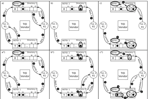
Here we will show two different scenarios. Firstly, a successful parallel commit involving two transactions that have disjoint read and write sets. Secondly, we show the behavior of the system when a transaction that has started the commit process (validation phase) is aborted. Thus, the parallel commit fails and we have to undo the changes done in the directory by the aborted transaction.
Figure 3.3 assumes that both processors have already asked for a TID and were assigned TID 1 and 2 respectively. P1 has written data fromDirectory 2, while P2 has written data from Directory 1. Note that the only difference between parts a* and a, is that in part a* P2 is also marked as sharer of line Y
in Directory 2.
To start with, we describe the example exposed in the first row where both processors are able to commit in parallel. In part a, P1 and P2 probe the
direc-TID Vendor NSTID: 2 ... Directory 1 P1 P2 M O NSTID: 1 ... Directory 2 P1 P2 M O P1 P2 Tid: 1 Tid: 2 b) TID Vendor NSTID: 3 ... Directory 1 P1 P2 M O NSTID: 3 ... Directory 2 P1 P2 M O P1 P2 Tid: 1 Tid: 2 c) TID Vendor NSTID: 2 ... Directory 1 P1 P2 M O NSTID: 1 ... Directory 2 P1 P2 M O P1 P2 Tid: 1 Tid: 2 b*) TID Vendor NSTID: 3 ... Directory 1 P1 P2 M O NSTID: 3 ... Directory 2 P1 P2 M O P1 P2 Tid: 1 Tid: 2 c*) X Y X Y Commit 1 Commit 1 X X Y Y TID Vendor NSTID: 2 ... Directory 1 P1 P2 M O NSTID: 1 ... Directory 2 P1 P2 M O P1 P2 Tid: 1 Tid: 2 a*) Y X Skip 1 NSTID Probe NSTID 1 NSTID 2 NSTID Probe Skip 2 2 1 1 1 1 2 3 TID Vendor NSTID: 2 ... Directory 1 P1 P2 M O NSTID: 1 ... Directory 2 P1 P2 M O P1 P2 Tid: 1 Tid: 2 a) Y X Skip 1 NSTID Probe NSTID 1 NSTID 2 NSTID Probe Skip 2 2 1 1 1 1 2 3 Mark X Mark Y 1 1 2 2 3 Mark Y Mark X NSTID Probe NSTID 1 1 1 1 2 2 2 Commit1 Invalidate Y 2 2 Inv. Ack 3 4 4 Abort 2 3
Figure 3.3: Two scenarios attempting to commit a couple of transactions in parallel. Note that in both scenarios the messages generated at the beginning are the same, but in part a) P2 is not marked as sharer of line Y in Directory 2.
tories in their write sets and send the needed Skip messages 1y. Both processors
receive as answer of the probing a TID that matches their own TID 2y3y. Since
theread sets coincide with the write setsno extra probing is needed and validation phase finishes for both.
In parts b and c, a parallel commit takes place. In part b, both processors send aM arkmessage to the directory where they wrote to;P1 sends the message
to Directory 2 and P2 to Directory 1 1y. In part c, commit messages are
sent 1yand the directories update concurrently the sharers list, the owner and
the NSTID register 2y.
The second row shows an example where parallel commit fails andP2’s trans-action has to abort because it read a line from Directory 2, andP1 will commit there due to its lower TID. In part b*,P2 has to probeDirectory 2 because is in
itsread set 1y. MeanwhileP2 also sends aM arkmessage toDirectory 1since it
is ready to service TID 2. Note that M arkmessages can be sent before finishing the validation phase. P2 receives an answer of the probing with N ST ID 1 2y,
which is smaller than its own TID, thus it cannot proceed. It will have to keep probing until the NSTID received is higher or equal than its own. So two commits that involve the same directory, Directory 2 in this case, must be serialized.
In part c*,P1has finished the validation phase and the marking process, thus it can send theCommitmessages to the set of directories involved in the write set (i.e.,Directory 2) 1y. Once the directory receives theCommitmessage, it
gener-ates invalidations to the other sharers of the committed cache-line while updgener-ates the ownership 2y. Since line Y was speculatively read by P2, the Invalidation
message causes it to abort. Since P2 had already sent M ark messages, it has to send an Abort message to every directory where M ark messages where sent, so
an Abortmessage is sent to Directory 1 3y, which causes the directory to clear
all the marked bits and to update its NSTID 4y. Note that once the necessary
aborts are sent, P2 also needs to send an Invalidation Ack message that will cause Directory 2 NSTID register to be updated. This is necessary to avoid certain race conditions; resolves the situation in which a transaction with TID Y is allowed to commit because it received N ST ID Y as an answer to its probe before receiving an invalidation from transaction X with X < Y.
3.2
The M5 Simulator
In order to test our implementation and evaluate performance of the HTM mod-ule we will use The M5 Simulator (12), a research tool for computer system architecture widely used by the community. A complete list of publications using this simulator can be found here (4).
3.2.1
Key Features and Configuration Choices
One of the most important features of the simulator and also very important to make it change-prone is its pervasive object orientation. All the major simulation structures (CPUs, busses, caches, etc.) are represented as objects, M5’s internal
object orientation (using C++) provides in addition the usual software engineer-ing advantages. Usengineer-ing a quite simple configuration language that allows flexible composition of this objects we can describe complex simulation targets. This is important for us, because we will have to modify the simulator in order to use our own cache, directory and HTM objects amongst others.
M5 supports multiple interchangeable CPU models, currently there are three different models: a simple in-order CPU; a detailed out-of-order CPU that is superscalar and has simultaneous multi-threading (SMT) capabilities; and a ran-dom memory-system tester. The first two models use a common high-level ISA description, we will make some modifications over this ISA to provide new in-structions to support transactional executions. We used the AtomicSimpleCPU, it is an in-order, one cycle per instruction CPU. This choice is not done to sim-plify the system, but for consistency with the HTM literature since there are just a few proposals of HTM’s using out-of-order CPUs, and as they proved it is quite challenging (36).
M5 features a detailed event-driven memory system, including non-blocking caches over a simple snooping coherence protocol. Since we need a directory-based coherence protocol as shown in the previous section, we have to develop our own implementation for the memory hierarchy (caches, main memory banks and directories). Thanks to M5’s object orientation, instantiation of multiple CPU objects within a system is trivial. Combined with our module that will define the memory hierarchy we can easily simulate the desired system.
The simulator supports either full-system and system call emulation execution modes. We are interested in full-system capabilities to be able to have a functional environment able to interact with a disk image for example, since we will store our test binaries there. Full-system mode is only available in Alpha and SPARC architectures. Alpha can boot an unmodified Linux 2.4/2.6 kernel as well as FreeBSD, while SPARC can boot Solaris with some constrains. We chose Alpha architecture to be our testing platform, because using Linux we are sure that all the tests that we will use to evaluate performance and scalability will work properly. Note that no Alpha hardware is needed to make full use of M5 compiled with Alpha architecture, because Alpha binaries to run on M5 can be built on x86 systems using gcc-based cross-compilation tools.
Furthermore, M5 is being released under an open source license. It implies an active community around it with good support from its main developers.
Related Work
There have been a number of proposals for Transactional Memory (TM) over the last years. In this chapter we will walk through some of them to provide a global view of the research done by the TM community.
TM proposals that use pessimistic conflict detection such as Log-TM (29) and Unbounded TM (UTM) (11), write to memory directly (eager data versioning). This improves the performance of commits, which are more frequent than aborts. However, it may also incur additional violations not present in lazy data version-ing. Moreover, UTM tries to address the problem of limited hardware buffering capabilities, by providing mechanisms to support transactions of arbitrary size and duration in a pure hardware approach. However, UTM is not unique in this field, Virtualizing TM (30) provides different mechanisms that shield the programmer from various platform-specific resource limitations.
Scalable-TCC is based on a previous work called TCC (23), it was the first hardware TM system with lazy data versioning and optimistic conflict detection. However, TCC suffers from two major bottlenecks. First, it utilizes an inher-ently non-scalable communication medium between processors (common bus); and second, all commits are serialized with a commit token which has to be ac-quired by a transaction at commit time. With Scalable-TCC (19) both problems are addressed.
New proposals are trying to come up with new ideas to take the best of both worlds, lazy-like systems and eager-like systems. Eager-lazy HTM (EazyHTM)
scalable and easy to implement. Detecting conflicts while the transaction is run-ning makes commit process much faster, and delaying the resolution at commit time does not incur additional violations.
Architectural Details
In this chapter we discuss the architecture used and the decisions we took about the architectural setup of the whole system. Furthermore, we explain in detail the internals of each main component present in the system.
5.1
Architecture Overview
There are a lot of things to take into account and to decide when setting up such a complex architecture (e.g., interconnection network used, cache hierarchy setup, etc.). Our system is composed of 4 main components: the interconnection network; the directories; the main memory banks; and the processors. As we can see in Figure 3.1 the system is organized in nodes, each one has a directory, a processor and a main memory bank. Nodes communicate with each other through an interconnection network (ICN). In the following sections we explain in detail each component.
5.2
The Processor
Figure5.1shows the internals of the processor we are simulating. As we can see in the figure we will use two levels of private data cache (L1 and L2), both tracking the speculatively state of the cache-lines read and/or written by the transactions. In the CPU side there is a structure called Register File Checkpoint. This structure is a replication of the register file present in any CPU. The register
file is an array of processor registers. Each architecture has its own set of pro-cessor register of different kinds, such as: address registers, which are used by instructions that indirectly access memory; data registers, used to hold numeric values like integers and floating-point values; special purpose registers, including the program counter or the stack pointer; and many others. Thus, the Register File Checkpoint is used to take a snapshot of the current register file state at the beginning of a transaction (i.e., when a begin transaction instruction is ex-ecuted). In case a transaction aborts, the CPU uses the snapshot to restore its state, this is necessary because we have to restart the execution of the transac-tion to maintain atomicity and we need the CPU to be in the same exact state it was when the transaction started. Note that if we restore the checkpoint, the program counter will point to the first instruction of the aborted transaction (i.e., its begin transaction instruction).
Speculative state is stored in L1 and L2 caches. Note that we do not need non-speculative state tracking since we assume an always-in-transaction scenario, thus all memory accesses are transactional. Figure 5.1 presents data cache or-ganization. Tag bits include dirty (D), valid (V), speculatively-read (SR) and
speculatively-modified (SM) bits. We have cache-line level speculative state track-ing with one bit per field, but word-level tracktrack-ing is also possible addtrack-ing more bits to the SR, SM and V fields. In a 32 bytes cache-line configuration, 8 bits per line and per field would be needed.
The SM bit indicates that the corresponding cache-line has been modified during the execution of a transaction. Similarly, the SR bit indicates that its line has been read by a transaction. The valid bit as its name indicates marks invalid data in the cache. Finally, the dirty bit is used to support write-back protocol, we check the dirty bit on the first speculative write in each transaction. If the bit is already set, we first write-back that line to a non-speculative level of the memory hierarchy, in this case, to its associated main memory bank that can be located in any node of the system.
As we said, we will use two levels of private cache. In fact, we need them be-cause we need enough room to store all the speculative memory accesses of a run-ning transaction, and with just one level of cache this would be very difficult even
Communication Assistant (CA) Register File Checkpoint CPU Data Cache L1 D V SR SM TAG DATA D V SR SM TAG DATA Data Cache L2 Write−set Addresses Load/Store Address Load/Store Data Load/Store Address Load/Store Data Read−set Addresses Commit Commit Addresses Commit Data Commit Control Snoop Control Fill Control Commit Addres In Data In Refill Data Commit Data Out Commit Addres Out Violation
Figure 5.1: Detailed view of the processor internals.
for medium sized transactions since L1 caches tend to be small (∼32KB). How-ever, some researchers have shown that, with relatively large L2 private caches (∼512KB) tracking transactional state, it is unlikely that overflows occur in the common case (21). Moreover, there are mechanisms to deal with the problem with some performance penalties, of course (20;30).
We will use set associative caches since they provide a good trade-off between hit servicing time and miss rate. Direct mapped caches have the fastest hit times since only one cache position has to be checked to know if a certain line is in the cache, while in a full associative cache all positions have to be checked, but they have the lowest miss rate because any cache-line can be placed to any position (2). As for the replacement policy, when it comes time to load a new line and evict (remove from cache) an old line, we use last recently used (LRU) policy in
a per-set basis.
The last two components we want to remark are the write set and the read set. The first one stores all the written addresses during a transaction of the lines that need to be committed in a FIFO structure. The read set is used to determine weather to violate and abort or just invalidate the line from the caches when an invalidation message is received.
5.3
The Directory
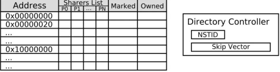
The directory tracks information for each cache-line in the main memory housed in the local node. This information involves a sharers list, a marked bit and an owned bit as shown in Figure 5.2.
0x00000000 0x00000020 0x10000000 ... ... ... ... Directory Controller NSTID Skip Vector ... PN
Sharers List Marked Owned
Address P0 P1
Figure 5.2: Detailed directory structure view.
The sharers list indicates the set of processors that have speculatively accessed the line, so when the line gets committed invalidations will be sent to those nodes. The Owned bit tracks the owner for each cache-line, the owner is the last node that committed updates to the line until it writes back to main memory (i.e, an eviction occurs or the line is requested by another node, thus it has to be removed from the private caches). The owner is indicated by setting a single bit in the sharers list and the owned bit. The Marked bit is used to indicate lines that are part of an ongoing commit to that directory. Each directory also makes use of a controller that consist in the NSTID register and a structure called skip vector, that allows the directory to keep track of unordered skip messages received.
Directories control access to a contiguous region of main memory. Only one transaction, at any time, can send state-altering messages to the memory region controlled by that directory, this transaction is the one that has the same TID
than the stored in the NSTID register of the directory. If a transaction has nothing to commit to a directory it will send a Skip message with its TID attached. This will make the directory mark the TID as completed. The key point is that each directory will either service or skip every transaction of the system. If two transaction have an overlapping write set, then the affected directory would serialize the commits; in this case, the transaction with the lower TID will always commit first, if the conflicting transaction is not aborted by the first one, then, it can commit later. In other words, a transaction with a higher TID will not be able to write to a directory until all transactions with lower TID have either skipped or committed that directory. Moreover, a transaction cannot commit until all transactions that could abort it have surely finished its execution. This makes the protocol livelock-free and forward process guaranteed.
During the commit process, for each directory that has a satisfactory NSTID, the transaction sends mark messages for the corresponding addresses in its write set. Once marking is complete for all directories involved in the write set and the transaction has received a NSTID higher than its own TID for each directory involved in the read set, the transaction commits by sending a multi-castCommit
message to the write set of directories. On receiving this message, each directory will gang-upgrade (all at once) marked lines to owned and generate invalidation messages if there are sharers other than the committing processor. If a transaction after sending mark messages is aborted, it will send abort messages that will make the directories gang-clear mark bits.
5.4
The Interconnection Network
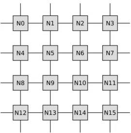
All the messages that have to go from one node to another will use the inter-connection network (ICN). We implemented a simple 2-D mesh ICN, as we show in Figure 5.3 with a setup of 16 nodes. We will assume a fixed value of latency per hope and we will always consider the shortest path between two nodes to calculate the cost of sending a message through the network.
N0 N1 N2 N3
N4 N5 N6 N7
N8 N9 N10 N11
N12 N13 N14 N15
Cache with Directory Module
In this chapter we introduce the module that allows to handle the definition of the cache hierarchy (L1, L2, etc.), main memory and directory structures using a DSM schema. Statistics are incorporated at cache, main memory and directory level; tracking events such as hits, misses and ticks spent amongst others.
In the following sections, details about the specification and implementation of the cache module are treated. First, we show in detail all the possible transitions that the cache can perform using a diagram, explaining the actions taken on each transition. Followed by the functionalities needed to be implemented for all the structures. Then, we show the possibilities that offer the statistics we implemented. Finally, the chapter concludes with a unit test example and the statistics obtained from its execution.
6.1
Cache State Transitions
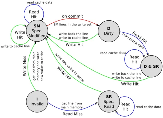
In Figure 6.1 we show a diagram of the state transitions that are possible in our cache implementation. It is based on five states that a line in the cache memory can have. These five states are the ones we explained in Section 5.2 plus an extra state, the “dirty and speculatively read” state. Since the hardware allows for combined states set in the caches, we can take advantage of this feature and serve as hits, without writing back, reads over dirty lines.
The diagram assumes only one level of cache, even though it extends to mul-tiple levels, because we always maintain all private cache levels consistent if
pos-sible; that is, if a line is in speculatively read state in L1 and L2, and a write takes place, we will access both levels to update data and state to speculatively modified. I Invalid D Dirty Write Miss Read Miss get line from main memory
get line from main memory and write new value to cache SM Spec. Modified Read Hit Write Hit SR Spec. Read Read Hit Write Hit
write new value to cache
on commit SM lines in the write set
Read Hit
Write Hit write back the line write to cache line write to cache line
read cache data
read cache data D & SR Read
Hit read cache data
read cache data
Write Hit write back the line write to cache line
Figure 6.1: Cache transitions state diagram.
Although Figure 6.1 is very clear, here is a brief explanation. We have to remember that any data modification is stored into the cache and must not be visible to the rest of the system. From each state we can either have a read or a write. At the beginning, when the cache is empty and the CPU wants to access a certain line, we will have a cache miss, thus we have to get the line from main memory and the resulting state will be either SM if the access was a write or SR if the access was a read. When in SM state any memory access will be a hit and data read or updated in place. On the other hand, with SR state, if a write takes place we have to change to SM state (updating data in place), but with reads the state remains unchanged. Note that in the graph we show a transition that takes place when committing a transaction, this transition is necessary to show how the dirty state is reached. From dirty state if a write takes place, the line needs
to be written back to main memory because it is the only copy of a “visible” portion of data, and then it has to be updated in place with the new value and state changed to SM. Upon a read we change state to dirty and SR which has the same behavior than dirty when a write is executed. We included the dirty and SR state in the diagram for clarity, since when an evict occurs, in both cases, we have to unset the owner in the directory and write back to main memory, but in the second case, a transaction could be aborted because the address might be part of the current transaction; thus, the actions taken are not exactly the same for both states in some cases.
It should be taken into account that the state of a cache line can change because of actions taken also by other CPUs, this is not represented in the graph. Possible scenarios are:
• On receiving an invalidate message for a given address, that line will im-mediately change its state to invalid. Note that we can never receive an invalidation message for a line in dirty state, because if the line is set as dirty it means that it is owned by the same processor in the corresponding directory.
• On receiving a data request message, in this case the line must be dirty, thus a write back takes place and the line is removed from the cache if it was in dirty state or left as SR if it was in dirty and SR state.
6.2
Configuration and Functionalities
This module implements functionalities of three structures: cache, main memory and directory. Here we will first show the configuration possibilities for these structures and then its main functionalities.
In the cache structure side we can set several configuration parameters, we now enlist the most important ones:
• Number of cache entries: A cache entry is a container with an associated direct index. In associative caches an address can only be stored in one of these entries that compose the cache. In Figure 6.2 we can see how an
associative cache is filled, this figure shows a cache with two direct entries with index 0 and 1.
• Associativity: The associativity of a cache determines how many cache lines can be stored inside a direct entry. In the example of Figure 6.2 the associativity is 2.
• Cache line size: As its name indicates this parameter sets the amount of bytes stored per cache line.
• Cache access cost: The cost that takes to access the cache and service the request. For example, if we have an L1 cache with 2 cycles access latency and an L2 cache with 10 cycles access cost, it would take 12 cycles to get a cache line stored in L2.
Main Memory . . . Index 0 1 2 3 4 Index 0, Way 0 Index 0, Way 1 Index 1, Way 0 Index 1, Way 1 Cache Memory
Figure 6.2: 2-Way associative cache fill.
The main memory structure also has some configuration parameters, the fol-lowing list shows them:
• Address space size: Determines the total amount of main memory that the system has distributed amongst all the nodes.
• Memory access cost: The cost that takes to access a main memory bank and service the request. Following the previous example, with an access latency of a hundred cycles, getting a cache line from main memory within the same node would cost 112 cycles.
Note that we are not talking about the 2-D Mesh interconnection network. This is because we will not represent it as a structure since we just calculate the minimum number of hops required to access or to reach a certain node from the source, and calculate the latency multiplying the number of hops by a configurable
hop latency.
Each one of the three mentioned structures (cache, main memory and direc-tory) has plenty of functionalities. Starting with the cache, the following list shows the most important functionalities that have to be implemented.
• Get Line: Services a memory access of a given type (read or write), ex-ploring the cache memory hierarchy in ascending order. If a hit occurs, we found the line in the caches; otherwise, we have to forward the request to the main memory level. Considering that accesses at main memory level are always a hit.
• Service Request: Services a request started by another CPU over an owned line that is present in this cache as dirty. The line is written back and invalidated from the caches if it was just in dirty state, or written back and left as sharer if it was in dirt and SR state.
• Invalidate Line: Instructs the cache to set as invalid a given cache-line address.
• Evict Line: Evict (remove) a given cache-line address of the cache if present, and also in the lower cache levels if any. When evicting a dirty line we have to write it back. Note that evict is used when there is not enough room to put another line inside the cache, thus evicting a line that is either in the read or the write set of a running transaction would abort the transaction.
• Line Present: To know if a line is present in any valid state inside the cache.
• Get Line Size: To know the size of the cache-line inthis cache, in bytes.
• Line Valid: Determines if an existing cache-line is in a valid state.
• Address to Entry: Function that relates an address with its associated direct entry in this cache.