Design of Massive Optical Interconnection
System for Data Centre Network
M
UHAMMAD
I
MRAN
S
TUDENT
N
UMBER
: 12210516
A Dissertation submitted in fulfilment of the requirements for the
award of Doctor of Philosophy (Ph.D.)
SCHOOL OF ELECTRONIC ENGINEERING DUBLIN CITY UNIVERSITY
Supervisor: Dr. Martin Collier
Co. Supervisor: Dr. Pascal Landais
Declaration
I hereby certify that this material, which I now submit for assessment on the pro-gramme of study leading to the award of Doctor of Philosophy is entirely my own work, that I have exercised reasonable care to ensure that the work is original, and does not to the best of my knowledge breach any law of copyright, and has not been taken from the work of others save and to the extent that such work has been cited and acknowledged within the text of my work.
Signed:
Candidate ID No: 12210516
Acknowledgement
In the Name of Allah, the Most Beneficent, the Most Merciful. First of all, I thank Almighty Allah, for giving me the strength to carry on this project and for blessing me with many great people who have been my greatest support in both my personal and professional life.
I would like to express my sincere gratitude to my supervisor Dr. Martin Collier and my co supervisor Dr. Pascal Landais for their continuous support in technical and non-technical matters related to my Ph.D studies, research work and thesis writing. I am also very thankful to Dr. Kostas Katrinis for his guidance.
I thank my all fellow lab mates for their help and support. Due to their company, my stay at Dublin City University was comfortable and enjoyable.
Last but not the least, I would like to pay my humble but full of emotion gratitude to my parents and Shaikh without their prayers and assistance this would not have been possible. I would also like to thank my entire family for providing me courage which I required most of the time during this work. I am very thankful to my loving wife, my lovely daughters Fatima and Momina, and my sons Hassan and Hussain for their love, support and patience.
CONTENTS
List of Figures x
List of Tables xv
1 Motivation 1
1.1 Traditional Data Centres Architecture . . . 2
1.2 Limitations of Traditional DCNs . . . 3
1.2.1 Power . . . 3
1.2.2 Traffic Locality . . . 4
1.2.3 Higher Bit Rates . . . 5
1.2.4 Scalability . . . 6
1.2.5 Latency . . . 6
1.2.6 Oversubscribed Network . . . 6
1.2.7 Performance . . . 7
1.3 Benefits of Optical Interconnects . . . 7
1.4 Challenges of Optical Interconnects . . . 8
1.4.1 Optical Switches . . . 8
1.4.2 Optical Switching . . . 9
1.5 Overview of Proposed Solution . . . 10
1.6 Thesis Structure . . . 13
2 Survey of Optical Interconnects for DCN 16
2.1 Introduction . . . 16
2.2 Optical Switches . . . 17
2.2.1 Slow Optical Switches . . . 17
2.2.2 Fast Optical Switches . . . 19
2.3 Evolution of Optical Interconnects for DCN . . . 23
2.4 Architectures based on MEMS . . . 24
2.4.1 Hybrid Electrical/Optical Switch . . . 24
2.4.2 Hybrid Packet/Circuit Switch . . . 25
2.4.3 Optical Switch Architecture . . . 27
2.4.4 Reconfigurable Architecture . . . 29
2.4.5 Hybrid Reconfigurable Architecture . . . 31
2.5 Architectures based on SOAs . . . 32
2.5.1 Optical Shared Memory Supercomputer Interconnect System . 32 2.5.2 Data Vortex . . . 34
2.5.3 Bidirectional Architecture . . . 35
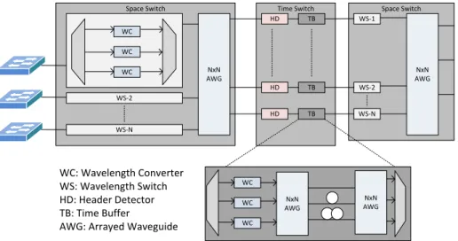
2.5.4 Space Wavelength Architecture . . . 36
2.5.5 Space Time Interconnection Architecture . . . 37
2.6 Architectures based on AWGRs . . . 39
2.6.1 Low-latency Interconnect Optical Network Switch . . . 39
2.6.2 TONAK-LION . . . 42
2.6.3 Petabit . . . 44
2.6.4 Integrated Router Interconnected Spectrally Project . . . 45
2.6.5 OFDM-based . . . 46
2.7 Architectures based on WSSs . . . 48
2.7.1 Mordia . . . 48
2.7.2 WaveCube . . . 49
2.7.3 Optical Pyramid Data center Network Architecture . . . 50
2.8 Architectures based on Fast and Slow Optical Switches . . . 51
2.8.1 LIGHTNESS . . . 51
2.8.2 Hybrid Optical Switching . . . 53
2.9 Comparative Analysis . . . 54
3 Hybrid Optical Switch Architecture: HOSA 58
3.1 Introduction . . . 58
3.2 Hybrid Optical Switch Architecture: HOSA . . . 60
3.2.1 Assumptions . . . 61
3.2.2 ToR Switch Design . . . 62
3.2.3 Dynamic Allocation of VOQs . . . 63
3.2.4 Control Packet Format for HOSA . . . 63
3.2.5 Burst Assembly/Disassembly . . . 65
3.2.6 Routing and Scheduling . . . 68
3.2.7 Switch Configuration . . . 80
3.3 Scalability Analysis of HOSA . . . 80
3.4 Cost and Power Consumption Analysis . . . 82
3.4.1 Fat Tree Network . . . 83
3.4.2 BCube Network . . . 85
3.4.3 Traditional Electrical Network . . . 87
3.4.4 Optical/Electrical Network . . . 88
3.4.5 HOSA . . . 90
3.4.6 Results . . . 93
3.5 Performance Analysis . . . 95
3.5.1 Simplified Model of HOSA . . . 96
3.5.2 Traffic Generation . . . 96
3.5.3 Simulation Scenarios . . . 99
3.6 Results and Discussion . . . 100
3.6.1 Limitations . . . 104
4 HOSA with Traffic Demand Scheduling 106
4.1 Introduction . . . 106
4.2 HOSA with TDS . . . 107
4.2.1 ToR Switch Design . . . 108
4.2.2 Burst Assembly/Disassembly . . . 108
4.2.3 Control Packet Format . . . 110
4.2.4 Control Plane Processing for HOSA with TDS . . . 110
4.3 Performance Analysis . . . 118
4.3.1 Traffic Generation . . . 118
4.3.2 Simulation Parameters . . . 119
4.3.3 Baseline Electrical Network . . . 120
4.4 Results and Discussion . . . 121
4.4.1 Latency . . . 121
4.4.2 Throughput . . . 123
4.5 Performance of the Control Plane . . . 126
4.6 Conclusion . . . 128
5 Performance Analysis of OBS over Fast Optical Switch Architecture for DCN129 5.1 Introduction . . . 129
5.2 Fast Optical Switch Architecture: FOSA . . . 130
5.2.1 Control Plane Processing . . . 135
5.3 Scalability Analysis of FOSA . . . 138
5.4 Performance Analysis . . . 139
5.4.1 Network Topology . . . 140
5.4.2 Traffic Generation . . . 140
5.4.3 Simulation Parameters . . . 141
5.5 Results and Discussion . . . 143
5.5.1 Latency . . . 144
5.5.2 Throughput . . . 145
5.5.3 Packet Loss Ratio . . . 148
5.5.4 Performance of the Control Plane . . . 149
6 Performance Evaluation of TCP over Fast Optical Switch Architecture for
DCN 152
6.1 Introduction . . . 152
6.2 TCP over OBS . . . 153
6.3 Performance Analysis . . . 155
6.4 Results and Discussion . . . 157
6.4.1 Throughput . . . 157
6.4.2 Completion Time . . . 160
6.4.3 Packet Loss . . . 161
6.4.4 Round Trip Time . . . 163
6.5 Conclusion . . . 164
7 Conclusions and Future Work 166 7.1 Conclusions . . . 166
7.2 Future Work . . . 168
Appendix A 172
LIST OF ABBREVIATIONS
AWG Arrayed Waveguide Grating
AWGR Arrayed Waveguide Grating Router
CRC Cyclic Redundancy Check
CAGR Compound Annual Growth Rate
DCN Data Centre Network
FDL Fibre Delay Line
FPGA Field Programmable Gate Array
FTO False Timeout
FWC Fixed Wavelength Converter
HOL Head Of Line
HOSA Hybrid Optical Switch Architecture
ICT Information and Communication Technologies
MEMS Micro-Electro-Mechanical System
MZI Mach-Zehnder Interferometer
NIC Network Interface Card
O-E-O Optical-Electrical-Optical
OBS Optical Burst Switching
OCS Optical Circuit Switching
OFDM Orthogonal Frequency Division Multiplexing
OSNR Optical Signal to Noise Ratio
OXC Optical Cross Connect
ROADM Reconfigurable Optical Add/Drop Multiplexer
RTT Round Trip Time
RTO Retransmission Timeout
SFP+ Small Form Factor Pluggable Plus
SOA Semiconductor Optical Amplifier
TCP Transmission Control Protocol
TDM Time Division Multiplexing
TWC Tunable Wavelength Converter
TDS Traffic Demand Scheduling
ToR Top of the Rack
VOQ Virtual Output Queue
WC Wavelength Converter
WDM Wavelength Division Multiplexing
WSS Wavelength Selective Switch
LIST OF FIGURES
1.1 Data Centre Architecture. . . 2
1.2 Power Consumption in DCNs[1]. . . 4
1.3 Traffic Movement in Data Centres from 2014 to 2019[2] . . . 5
2.1 MEMS Switch[3] . . . 18
2.2 WSS Switch[4] . . . 19
2.3 AWGR Switches . . . 20
2.4 Photonic Space Switches . . . 21
2.5 SOA-Based Switches . . . 22 2.6 Helios Architecture. . . 24 2.7 HyPaC Architecture. . . 26 2.8 OSA Architecture. . . 28 2.9 Reconfigurable Architecture. . . 30 2.10 HydRA Architecture. . . 31 2.11 Osmosis Architecture. . . 33
2.13 Bidirectional Architecture for DCNs. . . 36
2.14 Space Wavelength Architecture. . . 37
2.15 Space Time Interconnection Architecture. . . 38
2.16 DOS/LIONS Architecture. . . 40
2.17 TONAK-LIONS Architecture. . . 43 2.18 Petabit Architecture. . . 44 2.19 IRIS Architecture. . . 46 2.20 OFDM-based Architecture. . . 47 2.21 Mordia Architecture[6]. . . 48 2.22 WaveCube Architecture[7]. . . 49 2.23 OPMDC Architecture[8]. . . 51 2.24 Lightness Architecture. . . 52 2.25 HOS Architecture. . . 53
3.1 Proposed Architecture: HOSA . . . 60
3.2 ToR Switch Design . . . 62
3.3 Control Packet Format for HOSA . . . 64
3.4 Resource Allocation Mechanism using Horizon Scheduling, (a) Channel states before timeslot allocation and (b) Channel states after timeslot allocation. . . 73
3.5 Timeslot Allocation for HOSA: Case 1 . . . 76
3.6 Timeslot Allocation for HOSA: Case 2 . . . 76
3.7 Timeslot Allocation for HOSA: Case 3 . . . 77
3.8 Timeslot Allocation for HOSA: Case 4 . . . 78
3.9 Timeslot Allocation for HOSA: Case 5 . . . 78
3.11 Establishment of a new slow switch path using speculation approach. . 79
3.12 Total CAPEX cost and power consumption of different interconnection networks with respect to various values for the number of servers, (a) CAPEX Cost, (b) Power Consumption . . . 94
3.13 Total OPEX cost of different interconnection networks with respect to years using 40960 servers. . . 95
3.14 Load Vs End-to-End Delay for various timeout parameter and for vari-ous values of TDC: (a) TDC=1, (b) TDC=4, (c) TDC=8. . . 101
3.15 Load Vs End-to-End Delay for various capacities of fast and slow switches and for various TDC values: (a) TDC=1, (b) TDC=4, (c) TDC=8. . 102
4.1 HOSA with Traffic Demand Scheduling . . . 107
4.2 Control Packet Format for HOSA with TDS . . . 109
4.3 Timeslot Allocation for HOSA with TDS: Case 1 . . . 116
4.4 Timeslot Allocation for HOSA with TDS: Case 2 . . . 117
4.5 Establishment of a new slow switch path. . . 117
4.6 Topology diagram for the baseline traditional electrical network (Leaf-spine topology) . . . 120
4.7 Load Vs End-to-End Delay with various values of stability parameter for various TDC values using equivalent capacities of fast and slow optical switches. (a) TDC=1, (b) TDC=10, (c) TDC=20. . . 122
4.8 Load Vs End-to-End Delay for various capacities of fast and slow switches with various TDC values, at high stability: (a) TDC=1, (b) TDC=10, (c) TDC=20. . . 124
4.9 Average Bandwidth in (Gb/s) for various capacities of fast and slow switches with various TDC values: (a) TDC=1, (b) TDC=10, (c) TDC=20. 125 5.1 Fast Optical Switch Architecture. . . 131
5.2 Burst Assembly Cycle. . . 135 5.3 Load Vs End-to-End Delay measured in the fully subscribed network
for:(a) TDC=1, (b) TDC=10 and (c) TDC=20. . . 142
5.4 Load Vs End-to-End Delay measured with 2:1 oversubscribed network
for: (a) TDC =1, (b) TDC=10 and (c) TDC=20. . . 143
5.5 Load Vs Average Throughput measured in the fully subscribed network
for: (a) TDC =1, (b) TDC=10 and (c) TDC=20. . . 146
5.6 Load Vs Average Throughput measured with 2:1 oversubscribed
net-work for: (a) TDC=1, (b) TDC=10 and (c) TDC=20. . . 147
5.7 Load Vs Packet Loss Ratio measured in the fully subscribed network for:
(a) TDC=10 and (b) TDC=20. . . 149
6.1 Average throughput of the proposed design using OBS with the two-way reservation by considering different burst aggregation parameters
and with respect to different TDC values, (a) TDC =1, (b) TDC= 4,
(c) TDC=8. . . 158
6.2 Average throughput of OBS with traditional methods of one-way reser-vation by considering various burst aggregation parameters and for
var-ious TDC values, (a) TDC =1, (b) TDC=4, (c) TDC=8. . . 159
6.3 Performance analysis of TCP over conventional electronic packet switch-ing DCN for various values of TDC: (a) Average throughput achieved during first second of simulation time and completion time to transfer 1GB data from each server, (b) Packets loss and average round trip time of TCP segments. . . 160 6.4 Completion time to transfer 1GB data from each server for various
burst aggregation parameters and for various TDC values, (a) TDC=1,
(b) TDC=4, (c) TDC=8. . . 161
6.5 Packets loss for various burst aggregation parameters and for various
6.6 Average round trip time of TCP segments for various burst aggregation
parameters and for various TDC values, (a) TDC = 1, (b) TDC = 4,
(c) TDC=8. . . 163
LIST OF TABLES
1.1 Performance , Power and Cost Requirements for Data Centres[9],[2] 3
2.1 Comparison at a Glance . . . 54
3.1 Scalability Analysis of HOSA . . . 82
3.2 Cost and Power Consumption of Network Elements . . . 83
3.3 Simulation Parameters for HOSA . . . 97
4.1 Matrix Table . . . 111
4.2 Simulation Parameters for HOSA with TDS . . . 119
4.3 Performance of the Algorithms in the Control Plane . . . 127
5.1 Scalability Analysis for FOSA . . . 139
5.2 Simulation Parameters for FOSA . . . 141
5.3 Performance of the Control Plane in FOSA . . . 150
LIST OF ALGORITHMS
1 Control Packet Generation at ToR Switches for HOSA . . . 65
2 Bursts Generation at ToR Switch for HOSA . . . 67
3 Routing and Scheduling Algorithm for HOSA . . . 69
4 Control Plane Processing for HOSA with TDS . . . 112
5 Traffic Aggregation at ToR Switch . . . 133
6 Burst Transmission at ToR Switch . . . 134
Design of Massive Optical Interconnection System for
Data Centre Network
Muhammad Imran
Abstract
Effective optical interconnect is a fundamental requisite to realize Internet-scale data centres due to the capabilities and benefits of optical devices. Optical interconnects are energy efficient and support massive bandwidths. The performance of optical interconnects is directly related to the type of optical switches and optical switching techniques used. Optical switches may be categorized into slow optical switches and fast optical switches. The optical switching techniques are Optical Circuit Switching (OCS), Optical Packet Switching (OPS) and Optical Burst Switching (OBS).
This thesis presents three novel optical interconnection schemes which are based on optical burst switching. These schemes are called Hybrid Optical Switch Architec-ture (HOSA), HOSA with Traffic Demand Scheduling (TDS) and Fast Optical Switch Architecture (FOSA). The first two schemes are based on a hybrid design that utilizes fast and slow optical switches while the third scheme is based on using only fast optical switches. The proposed schemes consider OBS with a two-way reservation protocol that ensures zero burst loss. In the two-way reservation protocol, the connection is established for each burst before transmission. To evaluate the performance of these schemes, network-level simulation is used.
The proposed architectures consider a single stage core topology that can be easily scaled up (in capacity) and scaled out (in the number of racks) without requiring major re-cabling and network reconfiguration. The proposed schemes feature separate data and control planes. The control plane comprises a centralized controller while the data plane contains an array of optical switches. A scalability analysis of the proposed topology is presented and shows that this topology is scalable to hundreds of thousands of servers. This thesis also presents a trade-off between cost and power consumption of the proposed designs by comparing them with conventional interconnects using analytical modelling.
In HOSA, the key idea is to route high volume traffic through a fast optical switch during the reconfiguration of a slow optical switch. The traffic is moved to the slow optical switch once it is reconfigured. The aggregated traffic should be large enough so that it can bypass the slow optical switch during its reconfiguration phase. This technique hides the reconfiguration time of slow optical switch but the latency in-troduced due to burst aggregation is still high. In HOSA with TDS, small bursts are considered to reduce the latency of burst aggregation. The controller in HOSA with TDS technique maintains a traffic demand matrix which updates traffic demand on
periodic intervals and assigns slow paths for the high traffic volume. A resource al-location algorithm is proposed that allocates paths of fast and slow optical switches efficiently.
In HOSA with TDS, the control plane can only support applications that have high traffic stability. So for dynamically changing communication patterns, this thesis presents a new design called FOSA. The FOSA is based on only fast optical switches and it also uses OBS with the two-way reservation i.e. there is no additional burden on the control plane for maintaining traffic demands as was done in HOSA with TDS. The proposed technique shows considerable improvement in terms of throughput and packet loss ratio as compared to the traditional methods of OBS while performance comparable in terms of delay with the traditional methods of OBS is also achieved. The proposed technique also demonstrates performance comparable to that of electri-cal data centre networks.
The performance of TCP over traditional OBS network is degraded by the bursts losses due to contention even at a low traffic load. In FOSA, the performance of the TCP is evaluated. Since in the proposed scheme, the burst loss is zero due to two way reservation, the results show significant improvement of TCP performance in terms of throughput, time and packets loss as compared to the traditional methods of OBS and the conventional electronic packet switching data centre networks for all types of workloads.
LIST OF PUBLICATIONS
This work is based on the following contributions either published or in review phase at various places.
Journal Publications
1. Muhammad Imran, Martin Collier, Pascal Landais and Kostas Katrinis, "Software-Defined Optical Burst Switching for HPC and Cloud Computing Datacenters",
Journal of Optical Communications and Networking, 8.8 (2016): 610-620. (Im-pact Factor: 2.18).
2. Muhammad Imran, Martin Collier, Pascal Landais and Kostas Katrinis, "Perfor-mance Evaluation of TCP over Software-Defined Optical Burst-Switched Data
Center Network", invited paper submitted to Journal of Computational Science,
(Impact Factor: 1.078).
3. Muhammad Imran, Martin Collier, Pascal Landais and Kostas Katrinis, "Perfor-mance Evaluation of Hybrid Optical Switch Architecture for Data Center
Net-works"", Journal of Optical Switching and Networking, Best paper award, 21
(2016): 1-15,(Impact Factor: 1.137).
4. Muhammad Imran, Martin Collier, Pascal Landais and Kostas Katrinis, "Software-Controlled Next Generation Optical Circuit Switching for HPC and Cloud
Com-puting Datacenters",Electronics, 4.4 (2015): 909-921.
Conference Publications
1. Muhammad Imran, Martin Collier, Pascal Landais and Kostas Katrinis, "Perfor-mance Evaluation of TCP over Optical Burst-Switched Data Center Network",
In Computational Science and Engineering (CSE), 2015 IEEE 18th International Conference on, pp. 51-57. IEEE, 2015.
2. Muhammad Imran, Pascal Landais, Martin Collier,and Kostas Katrinis, "A data center network featuring low latency and energy efficiency based on all
opti-cal core interconnect", In Proceedings of the 17th IEEE International Conference
on Transparent Optical Network (ICTON), vol., no., pp.1,4, 5-9 July 2015, doi:
10.1109/ICTON.2015.7193537.
3. Muhammad Imran, Pascal Landais, Martin Collier,and Kostas Katrinis, "Per-formance Analysis of Optical Burst Switching with Fast Optical Switches for
Data Center Networks",In Proceedings of the 17th IEEE International Conference
on Transparent Optical Network (ICTON), vol., no., pp.1,4, 5-9 July 2015, doi:
10.1109/ICTON.2015.7193596.
4. Muhammad Imran, Martin Collier, Pascal Landais and Kostas Katrinis, "HOSA:
Hybrid Optical Switch Architecture for Data Center Networks", In Proceedings
of the 12th ACM International Conference on Computing Frontiers (CF’15), p.27,
doi: 10.1145/2742854.2742877.
5. Muhammad Imran, Martin Collier, Pascal Landais and Kostas Katrinis, "Energy
Efficient Data Center Network based on Slow and Fast Optical Switches",In
CHAPTER 1
MOTIVATION
Internet traffic has been increasing exponentially over the last few years due to the emergence of new end user applications which are based on cloud computing infras-tructure. These applications run on the servers deployed in the data centres and re-quire huge network bandwidths. The major infrastructure of today’s Internet com-prises data centres. Data centres provide a number of services from social networking to large-scale scientific calculations. They can be defined as big centres of storage and computing resources that communicate extensively with each other to serve the
ever-increasing demands of customers[10].
The data centres are getting more and more importance in our lives because the cloud computing has shifted computation and storage away from desktops to
large-scale data centres[11]. With the advancements of smart mobile devices and increasing
bandwidth demands for multimedia applications and other data services, IP traffic will
keep on increasing at an exponential pace[12, 13].
Apart from the demands of increasing bandwidth, it is predicted that the informa-tion and communicainforma-tion technologies (ICT) industry will contribute 2 to 3 percent of
1.1. TRADITIONAL DATA CENTRES ARCHITECTURE
being ICT infrastructure need to be evaluated in terms of interconnection design to support very large scales while leading to ultimate footprint and power savings.
1.1
Traditional Data Centres Architecture
Internet ToR Switches Servers in Rack Aggregate Switches Core Switches Content Switches and Load balance
Gateway Router
Clients
Data Centres Architecture
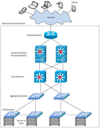
Figure 1.1. Data Centre Architecture.
There are various types of data centres such as computational, storage and high performance computing (HPC) etc. This thesis targets computational data centres. The traditional architecture of the computational data centre network (DCN) is based on a hierarchical design as shown in Figure 1.1. It features several layers of electrical switches. At the front end, the content and load balance switches are connected to the internet through the gateway routers, while at the back end, they are linked to the core switches. The core switches are linked to the aggregate switches and the aggregate
1.2. LIMITATIONS OF TRADITIONAL DCNS
switches are connected to the Top of the Rack (ToR) switches. Each ToR switch is connected to the servers in the rack. All the switches feature an electronic switch fabric and the links between them can be either copper cables or optical fibres. In the case of optical fibre links, optical-electrical-optical (O-E-O) conversion is required at every port of the switch. When a request comes from the external network, it first comes to the load balance and content switches which route the request to the appropriate servers. To fulfil the request, the servers can coordinate with other servers within the same or different racks. For example, the application servers can coordinate with the database servers to process the request. After completing the request, the response is sent to the external network through the gateway routers.
Table 1.1. Performance , Power and Cost Requirements for Data Centres[9],[2]
Year Peak Performance Power Consumption Equipment Cost Bandwidth
2012 10PF 5MW $225M 1Pbytes/s
2016 100PF 10MW $350M 20Pbytes/s
2020 1000PF 20MW $500M 400Pbytes/s
1.2
Limitations of Traditional DCNs
There are significant challenges to meet the growing performance requirements with current computational data centre architectures. These are described below.
1.2.1
Power
The electrical switches at different layers of a DCN and the transceivers required for O-E-O conversion are significant sources of power consumption in traditional DCN designs. The power consumption of the current interconnection network incurs 23% of the total IT power consumption in a DCN as shown in Figure 1.2 while it is predicted that the interconnection network will incur a much higher percentage of overall IT
power consumption in future DCNs[15]. In traditional DCNs, the power consumption
1.2. LIMITATIONS OF TRADITIONAL DCNS
of ToR switch. For example, the power consumption of one port of ToR switch is 3.7
watt [16] while it is 12.4 watt for aggregate/core switch [17]. Exact proportion of
power consumption for ToR, aggregate and core switches varies with the number of ports of these switches in DCN. It is shown in Table 1.1 that the peak performance required of data centres will continue to rise tremendously but the affordable budget for the total permissible power dissipation by the data centres is increasing at a much slower rate i.e. it doubles every 4 years due to various thermal dissipation factors.
Storage 37% Servers 40% Network 23% Power Consumption in DCNs
Figure 1.2. Power Consumption in DCNs[1]
The power dissipation of the data centres also has a significant effect on the envi-ronment. It has been reported in 2007 that data centres accounted for 14% of the total
ICT greenhouse gases emissions and it is expected to grow up to 18% by 2020[18].
1.2.2
Traffic Locality
The projection of traffic growth in data centres according to the Cisco cloud index
[2] is shown in Figure 1.3. Observe that during the period from 2014 to 2019, the
majority of data centre traffic will remain within the data centre while only a small portion of the traffic will go to the external network. Some of the traffic will also
1.2. LIMITATIONS OF TRADITIONAL DCNS
be exchanged between data centres for distributed and replicated services between databases in different data centres. Due to this high traffic locality, high bandwidth and low latency interconnections are required.
0 1000 2000 3000 4000 5000 6000 7000 8000 9000 2014 2015 2016 2017 2018 2019
Eb
yt
es/y
ea
r
Year
Data center to user Data center to data center Within data center
Figure 1.3. Traffic Movement in Data Centres from 2014 to 2019[2]
1.2.3
Higher Bit Rates
The performance of communication systems at high data rates using electrical trans-mission lines is degraded by dielectric losses and losses incurred due to skin effect. Power dissipation increases as data rates increase in electrical transmission lines. For example, for 10 Gig E, power restrictions limit cable length to about 10 m. Longer
ca-bles are possible, but power can exceed 6 W/port which is not feasible in large-scale
data centres [19]. On the other hand, there is no power consumption in optical fibre
because it is a passive device. However, there is attenuation in optical fibre but it is independent of the data rate. Higher data rates in optical fibre can be achieved by en-gineering a better laser or by using digital signal processing. For example, University College London (UCL) researchers have achieved 1.125 terabits per second over fibre
1.2. LIMITATIONS OF TRADITIONAL DCNS
1.2.4
Scalability
An architecture based on ethernet links and switches (with limited capacity) will be very challenging to manage as the traffic flowing within data centres continues to grow exponentially. The hierarchical design cannot support the growing traffic in data cen-tres that will be equipped with more and more servers and also more microprocessor cores per server. The future data centres must have the capacity to incorporate hun-dreds of thousands of servers. Large cloud computing data centres owned by
Ama-zon, Microsoft and Google have tens of thousands of servers[21]. With the expected
growth in data center traffic, the number of servers in data centres is destined to in-crease which poses a significant challenge to the data center interconnection network.
1.2.5
Latency
Latency is introduced by queuing in buffers and by propagation delays incurred by packets during transmission from one node to another. Packets have to be buffered by switches during packet processing and this delay can be large when there is congestion in the network. Although the switching speed of electronic switches is of the order of micro- or nano-seconds, overall end-to-end packet delay is significant and will need to be reduced in future data centres.
1.2.6
Oversubscribed Network
Traditional data centres networks are oversubscribed. For example, if 40 servers in a rack are connected with 1 Gbps link to the ToR switch and the ToR switch is connected by a 10 Gbps link to the aggregate switch, the network is oversubscribed by a 4:1 ratio. In the worst case scenario, if all the servers within the same rack generate 1 Gbps data to communicate with the servers in other racks, the 10 Gbps link will not have enough capacity to forward the 40 Gbps of data. There are various approaches proposed to solve the issue of over-subscription. One approach is to use intelligent workload placement algorithms to allocate network-bound service components to physical hosts
1.3. BENEFITS OF OPTICAL INTERCONNECTS
more network bandwidth to service components with heavy communications. Thus, even for a few thousand servers, uniformly high capacity networks appear to be an overkill. As the size of the network grows, this weighs on the cost, power consumption and complexity of such networks.
1.2.7
Performance
The performance of data centres has been increasing on the order of 10 times every 4 years with bandwidth increasing on the order of 20 times in the same interval as shown in Table 1.1. Power consumption can only be allowed to increase perhaps twofold and cost by a factor of 1.5.
1.3
Benefits of Optical Interconnects
An optical interconnection system can meet the above mentioned challenges due to the properties of optical components. Optical switches are power efficient and consume less power than electrical switches. For example, electronic packet switches consume 12.5 W power per port which is 50 times higher than micro-electro-mechanical system (MEMS) based optical switches which only consume 0.24 W power per port while the
cost per port of both type of switches is approximately the same, i.e. $500[23].
Optical interconnects can provide high capacity links to meet requirements for traffic locality and higher bit rates by using optical fibres and optical transceivers. Re-searchers from Bell Labs successfully sent data at the speed of 31 Terabits-per-second over 7200km in an experiment done at Alcatel-Lucent’s Innovation City campus in
Villarceaux near Paris [24]. There is an increasing trend for using 10 Gig Ethernet
network interface cards (NICs) in servers. Google has 10 Gig E deployments and is
pushing the market for 40/100 Gig E[25]and this is only feasible with optical fibres.
In the near future, higher bandwidth transceivers are going to be adopted (for 40 Gbps
and 100 Gbps Ethernet) such as 4×10 Gbps Quad Small Form Factor Pluggable(QSFP)
1.4. CHALLENGES OF OPTICAL INTERCONNECTS
10 Gbps channels. Higher data rates could also solve the oversubscription problem by providing full bisection bandwidth in fully subscribed network.
1.4
Challenges of Optical Interconnects
There are significant challenges to be addressed before designing an optical inter-connection system for DCN. The performance of the optical interconnects is directly related to the type of optical switches and their underlying optical switching technolo-gies. These are described below.
1.4.1
Optical Switches
Traditional optical switches are based on MEMS technology. The attractive features of MEMS switches include: a) excellent power efficiency due to the use of passive switching, b) high port density, c) low insertion loss and crosstalk, d) an absence of transceivers due to using all-optical switching, e) lower cost, f) support of bidirectional communication, and g) data rate independence. They are also highly scalable and are
commercially available e.g. 3D-MEMS[26]. However, they have long switching times,
of the order of tens of milliseconds. Fast optical switches using technologies such as arrayed waveguide grating routers (AWGRs) and semiconductor optical amplifiers (SOAs) are now available. An AWGR is a passive device and works in combination with tunable lasers (TLs) or tunable wavelength converters (TWCs). The switching time of these switches is determined by the tuning speed of TLs or TWCs which is of
the order of a few nanoseconds[27]. An SOA works as an ON/OFF switch and also
compensates for losses that occur during transmission of optical signals. SOA switches
also have a switching time in the range of a few nanoseconds[28, 29]. Although both
types of switches are fast, they are expensive in comparison to MEMS switches of the same capacity. Wavelength Selective Switch (WSS) is an another type of optical switch that can distribute the incoming set of wavelengths to a different set of out-going wavelengths. The switching time of WSSs is in the range of microseconds to
1.4. CHALLENGES OF OPTICAL INTERCONNECTS
milliseconds[30, 31]. Further details about optical switches are provided in Chapter
2.
1.4.2
Optical Switching
Optical Switching techniques that exist in optical networks are optical circuit switching (OCS), optical packet switching (OPS) and optical burst switching (OBS). All these techniques have some advantages and disadvantages over one another.
The OCS is a connection oriented optical switching technique [32, 33]. In OCS,
a connection is established before data transmission on a pre-defined path from the sender to the receiver. A control packet is sent in advance to establish a link to the des-tination. Once the link is established, an acknowledgement is sent back to the sender and then the data transmission starts. The OCS does not require transceivers since it does not employ conversion between light and electricity i.e. no O-E-O conversion is required at intermediate core switches as the link is already established. Large connec-tion establishment time and bandwidth underutilizaconnec-tion in the case of low traffic load are the major limitations of the OCS. The wavelength continuity constraint is another limitation of the OCS. However, wavelength converters are used to address this limi-tation. The OCS has been widely used in the long-haul backbone optical network for many years. In backbone optical network, the connections are established for a long duration. There is a very infrequent demand to change the connection setup. For ex-ample, the connections between cities and countries in the long-haul optical network last for days and weeks. This has made OCS the preferred choice for the backbone optical network. MEMS switches are ideal switches to use with OCS because their long switching time does not limit performance.
The OPS is a connectionless optical switching technique[34–37]. In OPS, a packet
consists of a data and a header portion which are in the optical domain. When the packet arrives at the optical switch, the header is removed from the packet and is converted into the electrical domain for processing. During this processing time, the data in the packet has to be buffered in the node. Fibre delay lines (FDLs) are used for this purpose which can provide limited buffering by routing the light to the appropriate
1.5. OVERVIEW OF PROPOSED SOLUTION
fibres. The packet is dropped if the switch is not configured within this time. The processing speed of the switch controller should be compatible with the data rate of the incoming channel. Low processing speed of the switch controller also results in packet losses. The limitations of OPS are the lack of feasible optical buffers and packet losses in the case of output port contention or low processing speed of the switch controller. Fast optical switches are required to use OPS because of their low switching time.
The OBS[38–42]is different from OCS and OPS and is considered as a compromise
between them. It has a separate control and data plane similar to OCS. Packets are aggregated into a burst. A control packet is then transmitted on a dedicated control channel to reserve resources on all intermediate nodes from the source to the desti-nation. The burst is sent at a particular time after sending the control packet which is called the offset time. During the offset time, the burst is temporarily stored at the edge node before transmission. During this time, the switch controller at the core node processes the control information and sets up the switching matrix for the incoming burst. Burst loss due to output port contention is the major limitation of the OBS net-work. Output port contention can occur due to unavailability of a wavelength at the desired output port for an incoming burst. Several techniques exist in the literature
to avoid contention such as FDLs [43, 44], Deflection Routing [45, 46], Wavelength
Conversion [47] and Segmentation Based Dropping [48, 49] but none of them can
guarantee zero burst loss. OBS with a two-way reservation scheme ensures zero burst loss in which a control packet reserves resources across all intermediate nodes from the source to the destination and is sent back to the source as an acknowledgement. However, the control packet has a high Round trip time (RTT) for a large wide area optical network. This is because of the high propagation and switching delay.
1.5
Overview of Proposed Solution
In this thesis, novel optical interconnection schemes which are based on OBS are pro-posed. Historically, the OBS was proposed for the backbone optical core network but
1.5. OVERVIEW OF PROPOSED SOLUTION
it has not replaced OCS due to its limitation of high burst loss in this application. The proposed schemes consider OBS with a two-way reservation protocol that ensures zero burst loss. In the two-way reservation protocol, the connection is established for each burst before transmission. The two-way reservation is not suitable for long-haul backbone optical networks due to the high RTT of the control packet but for the pro-posed optical interconnect for the DCN, this RTT is not high for several reasons:1) the propagation delay is negligible, 2) faster optical switches are used at the core, 3) a fast optical control plane is used, 4) processing of the control packet is rapid and 5) a single hop topology is used. Network-level simulation is used to evaluate the performance of the proposed schemes.
In the first scheme, an optical interconnection scheme which is based on both fast and slow optical switches is proposed which is called hybrid optical switch architecture (HOSA). The proposed technique leverages strengths of both types of optical switches. The strengths of one type of optical switch compensate for the weaknesses of the other type. HOSA employs a single stage core topology that can be easily scaled up (in ca-pacity) and scaled out (in the number of racks) without requiring major re-cabling and network reconfiguration. HOSA features separate data and control planes. The control plane comprises a centralized controller while the data plane contains an ar-ray of fast and slow optical switches. The main idea is to route high volume traffic through the fast optical switch during the reconfiguration of the slow optical switch. The traffic is moved to the slow MEMS switch once it is reconfigured. This results in the overall switching time being that of the fast optical switch. A resource assignment algorithm is presented that allocates resources efficiently to ensure minimum latency. The scalability of the proposed design is evaluated by considering various capacities of servers in a rack and various ratios of fast and slow optical switches. A trade-off be-tween cost and power consumption of the proposed design using analytical modelling to compare it with conventional interconnects is also presented. Furthermore, the trade-off between the performance and the capacity of both types of optical switches is evaluated. In this scheme, large burst aggregation time is the major limitation i.e. the aggregated traffic should be high enough so that it can bypass the MEMS switch during its reconfiguration time.
1.5. OVERVIEW OF PROPOSED SOLUTION
In the second scheme, HOSA supplemented with a Traffic Demand Scheduling scheme is proposed to overcome the limitation of high aggregation time in HOSA. In HOSA with TDS, there is no need to aggregate a large amount of traffic. The con-troller maintains a traffic demand matrix which updates traffic demand on periodic intervals and assigns slow paths for the high traffic volume. A resource allocation al-gorithm is proposed in the control plane for efficient utilization of the resources that results in high throughput and low latency. However, similar to other hybrid
tech-niques[23, 50–54], HOSA with TDS has the limitation of the control plane overhead
to measure the communication patterns and calculate a new schedule. As a result, the control plane is limited to support only traffic with high stability. Stability refers to the duration of the traffic flows i.e. high stability refers to the traffic flows that last several seconds. Due to the limitation of the control plane, HOSA with TDS does not perform well for dynamically changing communication patterns. To overcome this limitation, this thesis presents a new optical interconnect called fast optical switch architecture (FOSA).
FOSA is based on only fast optical switches. In this design, only OBS with the two-way reservation is used. In FOSA, there is no extra processing overhead on the control plane for maintaining traffic demands as was done in the second scheme. This scheme works well for dynamically changing communication patterns. The proposed technique shows considerable improvement in terms of throughput and packet loss ratio compared to the traditional methods of OBS while delays comparable to those of the traditional methods of OBS are also achieved. The proposed technique also demonstrates performance comparable to that of electrical data centre networks.
Another reason that OBS has not replaced OCS in the long-haul optical network is because of its poor performance with TCP. The performance of TCP over a traditional OBS network is degraded by the wrong interpretation of congestion in the network. The burst losses due to contention can be misinterpreted by the burst losses due to con-gestion. The contention refers to the burst loss due to unavailability of a wavelength even at the low traffic load in the network. The performance of the TCP is evalu-ated on FOSA. As in the proposed scheme, the burst loss is zero due to the two-way reservation protocol; the results show significant improvement of TCP performance in
1.6. THESIS STRUCTURE
terms of throughput, time and packets loss as compared to the traditional methods of OBS. The proposed scheme also demonstrates more efficient TCP performance than the conventional electronic packet switching DCN for various types of workloads.
1.6
Thesis Structure
This section provides an overview of the later chapters of this thesis. The next chapter is a study of the existing efforts of the research community to resolve the challenges posed by data centre networks. The technical contribution of this research is docu-mented in the next four chapters and the last chapter contains conclusions.
Chapter 2 starts with the brief overview of various types of optical devices that could be of interest in designing an optical interconnection system for DCNs. After-wards, the detailed description of various types of optical switches used in optical net-works is presented. Various optical interconnects schemes that have been proposed for data centre networks are discussed and a brief overview of each architecture is provided. Finally, a comparative analysis of these optical interconnects is provided.
In chapter 3, the proposed design of the HOSA is presented. The detailed de-scription of the component design and various algorithms which are used in the ToR switch and in the control plane are discussed. A scalability analysis of the proposed in-terconnect, investigating various ratios of slow and fast optical switches, is provided. This chapter also presents an analysis of cost and power consumption of the pro-posed design, comparing it with other well-known interconnects. Furthermore, the performance of the system is evaluated using network-level simulation by considering various traffic workloads, and by using different capacities of slow and fast optical switches.
In chapter 4, HOSA with the TDS technique is discussed. The detailed descrip-tion of the proposed resource allocadescrip-tion algorithm in the control plane is presented. The performance evaluation of the system using network-level simulation, consider-ing diverse workload communication patterns and system design parameters, is also discussed.
1.7. SUMMARY OF CONTRIBUTIONS
Chapter 5 describes a new architecture FOSA which is based on using only fast optical switches. The detailed description of various algorithms used in the ToR and in the controller is provided. The scalability of the new design using only fast optical switches is discussed. The performance analysis is done by using network-level sim-ulation, comparing the proposed technique with traditional OBS and electrical data centre network.
In chapter 6, the performance issues of TCP over OBS networks are discussed. The performance of TCP over FOSA using network-level simulation is presented and a comparative analysis with traditional OBS and electrical data centre network is done. Finally, in chapter 7, an overview of the contributions, HOSA which is based on hybrid optical switch design, HOSA with TDS technique and FOSA design which is based on fast optical switches is given. Some future directions in the area of optical data centre are also discussed.
1.7
Summary of Contributions
Below is a list of technical contributions of this thesis for more clarity.
• Introducing a concept of two-way reservation scheme of OBS in data centre
network.
• Proposing a scalable hybrid optical switch architecture HOSA, which is based on
fast and slow optical switches using a single stage core technology.
• Performing scalability analysis of the HOSA.
• Performing cost and power consumption analysis of the HOSA and comparative
analysis with other well know interconnects.
• Analytical modelling of cost and power consumption analysis of the HOSA and
other well known interconnects.
1.7. SUMMARY OF CONTRIBUTIONS
• Proposing HOSA with TDS technique to improve HOSA.
• Evaluating the performance of HOSA with TDS using network-level simulation
and performing a comparative analysis with baseline electrical data centre net-work.
• Introducing a new design FOSA which is based on only fast optical switches.
• Assessing the performance of the FOSA using network-level simulation and
per-forming a comparative analysis with traditional OBS and with baseline electrical data centre network.
• Performing scalability analysis of the FOSA design using only fast optical switches.
• Evaluating the performance of TCP on the FOSA using network-level simulation
and performing a comparative analysis with traditional OBS and with a baseline electrical data centre network.
CHAPTER 2
SURVEY OF OPTICAL INTERCONNECTS
FOR DCN
2.1
Introduction
Data centres are experiencing an exponential increase in the amount of network traffic that they have to sustain due to the emergence of new end user applications which are based on cloud computing infrastructure. To meet the requirement of increasing bandwidth demand, large data centres are needed with thousands of servers inter-connected with high bandwidth switches. The traditional DCNs, based on electronic packet switches, consume excessive power and are unable to meet the increasing band-width demand of emerging applications. Optical interconnects have gained significant attention in recent years because they can be used to address the challenges of tradi-tional DCN. They can offer high throughput, low latency and low power consumption compared to the traditional DCNs.
This chapter presents a detailed survey on optical interconnects for DCNs which are categorized according to the type of optical switches used. Furthermore, it provides a
2.2. OPTICAL SWITCHES
qualitative comparison of the proposed schemes based on their main features such as optical switching techniques, connectivity, scalability, cost and power consumption.
This chapter starts with the brief overview of various types of optical switches. Afterwards, various optical interconnects schemes that have been proposed for data centre networks are discussed and a general insight on each architecture is provided. In the end, a comparative analysis of these optical interconnects is given.
2.2
Optical Switches
Optical interconnects can be realized by using optical switches and other optical com-ponents. In this section, optical switches are categorized with relevant to their
config-uration/switching time. Optical switches are divided into two types: 1) Slow optical
switches; and 2) Fast optical switches. Slow optical switches have a switching time in the millisecond scale while fast optical switches have switching time in the range of a few nanoseconds.
2.2.1
Slow Optical Switches
Slow optical switches are further divided into two types: 1) Micro electro mechanical system (MEMS) switch and 2) Wavelength selective switch.
MEMS Switch
The MEMS switch is the most common type of slow optical switch. It is also known
as an optical circuit switch. It uses an N×N crossbar of mirrors to direct a beam of
light from any input port to any output port where N is the number of input/output
ports. A schematic of its design is shown in Figure 2.1. The mirrors are attached
with small motors, each of which is about 1 mm2. The built-in controller processor
positions the mirrors in the bar or cross position to implement a desired connection matrix and receives remote requests to reconfigure the mirrors into a new connection
2.2. OPTICAL SWITCHES
Figure 2.1. MEMS Switch[3]
matrix. Repositioning the mirrors to a particular position takes some time which is
called reconfiguration/switching time[3, 55].
The attractive features of MEMS include: a) high port density, b) transceivers are not required due to all-optical switching, c) power efficiency due to passive switching, d) low insertion losses and crosstalk, e) data rate independent i.e. high link bandwidth can be achieved due to WDM technologies, f) support bidirectional communication, g) less expensive, and are based on mature technologies. All of these advantages come at the cost of switching time which is of the order of tens of milliseconds. These switches are mostly used in long-haul backbone optical network by using optical circuit switching for long-lived connections. MEMS switches with 384 ports (Polatis) and 320 ports (Calient) are commercially available while with as many as 1,000 ports
being feasible and hope to be available in the future [26, 56]. Research prototype of
MEMS optical switches has already scaled to more than a thousand input and output
ports[57].
Wavelength Selective Switch
Wavelength Selective Switch (WSS) is a device that can divide the incoming set of wavelengths to a different set of outgoing wavelengths. It is shown in Figure 2.2. Each set of wavelength is destined to a specific output port. The reconfiguration time
2.2. OPTICAL SWITCHES
Figure 2.2. WSS Switch[4]
of WSSs has been reported in the range of a few milliseconds [30] while an other
study has revealed it in the range of a few microseconds[31].
2.2.2
Fast Optical Switches
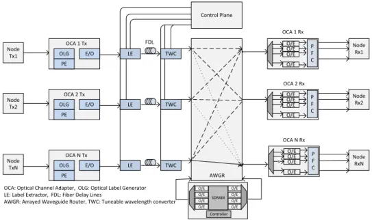
Fast optical switches are divided into three types: 1) AWGRs, 2) Photonic Space Switches and 3) SOA-Based Switches. Most of the optical interconnects using optical packet switching proposed in literature are based on AWGR and SOA based switches while photonic space switches combined with other optical switches also have the ca-pacity to use in future DCNs. All these switches have the switching time in the range of a few nanoseconds. These switches are described below:
AWGR Switches
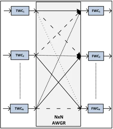
AWGs can also be used as a static WDM router called AWGR. AWGR is a combination
N(1×N)AWGs on the sender side andN(N×1)AWGs on the receiving side arranged
in a cyclic way where N is the number of input/output ports. It can provide strictly
non-blocking switching, if it is used with TWCs at the sender side and FWCs at the
receiver side [58]. Their design is shown in Figure 2.3. A TWC selects wavelength
according to the desired output port. A TWC provides a switching time in the range
of a few nanoseconds. An AWGR switch design with (512×512) ports has been
2.2. OPTICAL SWITCHES TWC1 TWC2 TWCN NxN AWGR FWC1 FWC2 FWCN
Figure 2.3. AWGR Switches
recently presented design, fabrication and characterization of(512×512)AWGR with
a channel spacing of 25 GHz[60].
AWGR as a router module is commercially available in 32×32 standard
configura-tions[61,62]. However, custom design with a large number of ports can also be made.
For example, AWGs with 128 channels are commercially available [63], so a router
module of AWGR with 128×128 configurations can be made by arranging them in a
cyclic way as described above.
Photonic Space Switches
Photonic space switches with(1×N)configurations have been built by using Polarized
Lead Zirconium Titanate (PLZT) waveguide technology[64]whereNis the number of
input/output ports. These switches are made by using(1×2)Mach-Zehnder with 3dB
couplers arranged in multiple stages to realize a (1×N)switch architecture. These
2.2. OPTICAL SWITCHES 1xN 1xN 1xN 1xN Nx1 Nx1 Nx1 Nx1 1 2 N-1 N 1 2 N-1 N
Figure 2.4. Photonic Space Switches
type of (1×N) switches has been presented by using phased array switching
tech-nology[65]. These switches use a single stage of phased array modulators between
star couplers instead of multiple stages of Mach-Zehnder modulators. An (N ×N)
strictly non-blocking switch fabric can be achieved by arranging these switches into
two stages. An example of an(N×N)switch configuration is shown in Figure 2.4. The
number of(1×N)switches required for an(N×N)implementation is 2N, half of them
arranged in a (1×N) configuration and the other half in an (N ×1) configuration.
A very large switch fabric can be achieved by arranging these switches in multiple stages in conjunction with SOAs in order to make good the losses introduced in op-tical transmission system. Unlike AWGR, these switches can be used in bidirectional
communication. Currently, switches with (1×16) configuration are commercially
2.2. OPTICAL SWITCHES SOA SOA SOA SOA SOA SOA SOA SOA SOA SOA SOA SOA SOA SOA SOA SOA 2 N-1 N 1 1 2 N-1 N Nx1 Coupler N (SOAs) N (SOAs) N (SOAs) N (SOAs) 1xN Coupler 1xN Coupler 1xN Coupler Nx1 Coupler Nx1 Coupler Nx1 Coupler 1xN Coupler Senders Receivers
Figure 2.5. SOA-Based Switches
SOA-Based Switches
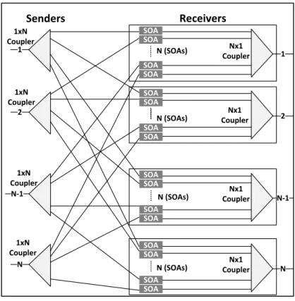
SOA-based switches are commonly realized using a broadcast-and-select architecture arranged in 3 stages as shown in Figure 2.5. First, the input signal is broadcast using
a(1×N)coupler. Each output of the(1×N)coupler is attached to one ofN SOAs per
output port. The SOA is used as a gate element and also provides optical gain in order to make up for the losses introduced by insertion and coupling. There are two states of SOAs: ON state and OFF state. SOAs consume different levels of power in these two states. In the ON state, they provide gain to the optical signal while in the OFF state they work as a gate switch i.e. they absorb optical signal. It has been reported
[29] that SOAs are required after every(1×32)coupling factor, in order to provide
gain to overcome the losses. A large scale strictly non-blocking switch comprising
(1024×1024)ports can be realized if two stages of SOA gates are used i.e. after the
first stage of SOAs, light is broadcast again by using(1×32)coupler to another stage of
SOAs. Optical Signal to Noise Ratio (OSNR) degradation is experienced by the optical signal after passing through more than 2 stages of SOAs. Proposed design of
SOA-2.3. EVOLUTION OF OPTICAL INTERCONNECTS FOR DCN
based switch in[29] is based on a simulation work and its practical implementation
is limited by its footprint and a large number of SOAs.
SOA-based switches with a large switching fabric are not available commercially but they can be built using individual components described above. However, foot-print and cost are the major concerns in building them in a large number of ports. A photonic integrated circuit (PIC) can be used to avoid these issues of SOA-based
switches. For example, a monolithic integration of 16×16 port SOA switch has been
demonstrated in [67, 68]. However, designing a large scale SOA-based switch using
PICs is quite a challenging task. In the foreseeable future, integrated photonics can play a major role to realize these switches at feasible cost and footprint.
2.3
Evolution of Optical Interconnects for DCN
Optical interconnects have gained significant attention recently, as they seem to pro-vide a promising and viable solution for future data centre networks compared to tradi-tional electrical architectures. This section presents the optical interconnects schemes that have been proposed for data centre networks and provides a general insight on each architecture.
Optical interconnects are categorized into five categories according to the type of optical switches used: (1) architectures based on MEMS, (2) architectures based on SOAs, (3) architectures based on AWGRs, and (4) architectures based on WSSs, and (5) hybrid architectures based on fast and slow optical switches. A comparative analysis on the features of these schemes such as connectivity, scalability, cost and power consumption is also provided.
2.4. ARCHITECTURES BASED ON MEMS
2.4
Architectures based on MEMS
2.4.1
Hybrid Electrical
/
Optical Switch
A hybrid electrical/optical switch (Helios) architecture for DCNs is proposed by[23].
Its architecture is shown in Figure 2.6. It consists of two level of switches called pod switches and core switches. The pod switch combines several ToR switches into a single unit and is interfaced to the core switches. Each pod switch typically holds between 250 and 1,000 servers. For simplicity, the ToR switch is considered as the pod switch here in Figure 2.6. The core switches are combination of electrical packet switches and MEMS switch which is also called optical circuit switch. Basic idea of this hybrid architecture is to use benefits of both electrical packet switches and MEMS switch. Bursty traffic between different pods is typically handled by the core electrical packet switches and long-lived, slowly changing inter-pod traffic is handled by the MEMS switch. The pod switch has a number of optical transceivers i.e. 10G Small
Core Electrical Packet Switches Optical Circuit Switch
ToR Switch
Servers in Rack Servers in Rack
10 G Fiber 20 G Super Link
Servers in Rack Mux
Figure 2.6. Helios Architecture.
2.4. ARCHITECTURES BASED ON MEMS
these transceivers are connected to the core electrical switches. The other half of these transceivers pass through a multiplexer which multiplex these links into a single WDM link which is called a super-link. Super-link is then connected to the MEMS switch. In this way, 50% of bandwidth is shared between electrical and optical switches.
Control plane in Helios consists of three collaborating modules: a Circuit Switch Manager (CSM), a Topology Manager (TM), and a Pod Switch Manager (PSM). The CSM is the built-in controller of Optical MEMS which is responsible to configure optical MEMS switch. TM runs on server and is responsible for monitoring inter-pod traffic demands and calculates new configurations for optical switch. The PSM runs on each pod switch. It coordinates with TM and controls switch hardware and flow table. Layer 2 or 3 forwarding can be used for electrical packets switching.
Helios has shown reduction in cost upto a factor of 3, reduction in complexity upto a factor of 6 and reduction in power consumption upto a factor of 9 as compared to typical data centres using electrical packet switches only. It is also reported that if 50% of inter-pod traffic changes over multi second time-scales then Helios shows good performance by mixing of these switches. The other plus point of the Helios is
usage of readily available optical/electrical components and reduced cost of upgrade.
Higher data rates with MEMS switch can be achieved without any additional cost and complexity.
2.4.2
Hybrid Packet
/
Circuit Switch
A hybrid packet/circuit switch (HyPaC)[50]is also a hybrid optical/electrical
inter-connection architecture for data centres similar to Helios. Its architecture is shown in Figure 2.7. It consists of traditional electrical packet switches at different layers (ac-cess, aggregate and core) and a MEMS switch that is connected with all ToR switches. Servers are connected to the ToR switches and ToR switches are connected to the elec-trical switches at aggregate layer and a MEMS switch. Aggregate switches are con-nected to the electrical core switches. Each ToR switch is concon-nected with exactly one ToR switch at a time by using optical network and this reconfiguration changes very slowly with the time. Reconfiguration is based upon traffic demands between racks.
2.4. ARCHITECTURES BASED ON MEMS
Pair of racks demanding high traffic communication are connected through the MEMS switch. The circuit switch network can only offer a matching on the graph of racks
and Edmonds algorithm [69]is used to compute matching between racks. HyPaC is
Core Switch
Aggregate Switch
ToR Switch
Servers in Rack
Optical Circuit Switch
Figure 2.7. HyPaC Architecture.
different from Helios in that the end hosts are responsible for traffic demand estima-tion while in Helios topology manager is responsible for this funcestima-tions. Traffic demand estimation is done by increasing the size of per-connection socket buffer and observ-ing end-host buffer occupancy at runtime. It needs extra kernel memory for bufferobserv-ing, but is transparent to applications and does not require switch changes. HyPaC sepa-rates the two networks by using VLAN based routing mechanism. End host tags each packet for specific VLAN and ToR switches are responsible for forwarding packet either to the optical switch or electrical switch based on the tag done by end host. Each host runs a management daemon that informs the kernel about the inter-rack connectivity. The kernel then de-multiplexes traffic to the optical and electrical paths properly. The optical configuration manager runs on the server and collects traffic measurements, determines how optical paths should be configured, issues configuration directives to the switches, and informs hosts which paths are optically connected.
HyPaC is suitable for certain types of applications which require huge data transfer components e.g. VM migration or backup of servers, skewed traffic patterns, and loose synchronization.
2.4. ARCHITECTURES BASED ON MEMS
Due to the large switching time of MEMS switch and the control plane overhead required for the estimation of traffic demand and the calculation of a new OCS topol-ogy, the control plane has the limitation to support applications that have high traffic stability, i.e. workloads that last several seconds. So Helios and HyPaC are suitable in scenarios where traffic stability is high. Power consumption is another limitation in these techniques due to the usage of electrical switches and power hungry transceivers at the core which is not desirable in future large scale data centres. Helios and HyPaC architectures are also not scalable because their scalability is limited by the constraint of the number of optical ports of the MEMS switch.
The performance degradation for hotspots (ToR pairs with high traffic demand) is another major limitation in these techniques. For example, if traffic demand of hotspots is higher than the maximum supported bandwidth in OCS-MEMS path then the performance bottleneck arises. Other MEMS based interconnects such as optical
switch architecture[54, 70], reconfigurable architecture[71, 72]and hybrid
reconfig-urable architecture [53] as describe in the next sections do not have this limitation
because they provide full bandwidth between any ToR pair.
2.4.3
Optical Switch Architecture
The optical switch architecture (OSA) for DCNs[54, 70]comprises a two layer
archi-tecture i.e. edge and core. At the edge, it consists of ToR switches while at the core, it consists of a MEMS switch. Its architecture is shown in Figure 2.8. Between MEMS and ToR switches, it uses a wavelength selective switch in combination with
multi-plexer/demultiplexer, coupler and circulator at the core. Servers are connected with
ToR switches. ToR switches have N number of distinct wavelength transceivers. These transceivers use distinct fibres to connect to send and receive infrastructures. On the sending fibre links, these are multiplexed into one single fibre link and are divided by
kset of wavelengths using WSS wherek<N and each of the kgroup is transmitted
on its own fibre by the WSS. On the receiving end, thesekgroups are first coupled into
single fibre by using coupler and then are demultiplexed into different wavelengths where they are then connected to the receivers.
2.4. ARCHITECTURES BASED ON MEMS
Optical Switching Matrix
DEMUX WSS coupler MUX Optical MUX, DEMUX & Switching Components Optical MUX, DEMUX & Switching Components ToR Switches Servers in Rack
Figure 2.8. OSA Architecture.
The main theme of the OSA is to connect ToR switches through the MEMS switch by a single hop that generate high inter-rack traffic, while bursty and low volume traffic are assigned to multi-hop connections. For example, ToR A has a large amount of traffic to send to the ToR B and ToR B has a large amount of traffic to send to the ToR C. ToR A also has a small amount of traffic to send to the ToR C. So in this case, ToR B is connected to the ToR A and C directly through the MEMS switch by a single hop and traffic from ToR A to C is first sent to the ToR B which forwards the traffic to the ToR C. The intermediate ToR switches in multi-hop path receive the packet and convert it into an electrical signal for processing, and then regenerate the packet into optical domain by optical transceiver for destination ToR switch. In this way, low volume traffic can take more than one hop to reach its final destination.
The decisions of MEMS switch configuration are made by topology manager (TM) which is connected with MEMS, WSS and ToR switches. The TM gets traffic matrix