Durham Research Online
Deposited in DRO:
26 April 2016
Version of attached le:
Accepted VersionPeer-review status of attached le:
Peer-reviewedCitation for published item:
Shahbazi, M. and Saadate, S. and Poure, P. and Zolghadri, M.R. (2016) 'Open-circuit switch fault tolerant wind energy conversion system based on six/ve-leg recongurable converter.', Electric power systems research., 137 . pp. 104-112.
Further information on publisher's website:
http://dx.doi.org/10.1016/j.epsr.2016.04.004Publisher's copyright statement:
c
2016 This manuscript version is made available under the CC-BY-NC-ND 4.0 license http://creativecommons.org/licenses/by-nc-nd/4.0/
Additional information:
Use policy
The full-text may be used and/or reproduced, and given to third parties in any format or medium, without prior permission or charge, for personal research or study, educational, or not-for-prot purposes provided that:
• a full bibliographic reference is made to the original source • alinkis made to the metadata record in DRO
• the full-text is not changed in any way
The full-text must not be sold in any format or medium without the formal permission of the copyright holders. Please consult thefull DRO policyfor further details.
Durham University Library, Stockton Road, Durham DH1 3LY, United Kingdom Tel : +44 (0)191 334 3042 | Fax : +44 (0)191 334 2971
Abstract— In this paper, an FPGA-controlled fault tolerant back-to-back converter for DFIG-based wind energy conversion
application is studied. Before an open-circuit failure in one of the semiconductors, the fault tolerant converter operates as a conventional back-to-back six-leg one. After the fault occurrence in one of the switches, the converter will continue its operation with the remaining five healthy legs. Design, implementation, simulation and experimental verification of a reconfigurable control strategy for the fault tolerant six/five leg converter used in wind energy conversion are discussed. The proposed reconfigurable control strategy allows the uninterrupted operation of the converter with minimum affection from an open-circuit switch failure in one of the semiconductors. Software reconfiguration is also necessary in PWM signal generation unit, to assure that proper gate signals are calculated and generated based on the actual five-leg structure Simulations and experimental tests are carried out and the results are presented and compared. They all confirm the capability of the studied reconfigurable control and proposed fault tolerant architecture in ensuring the system’s service continuity.
Index Terms— Wind Energy Conversion System (WECS), Field Programmable Gate Array (FPGA), Fault Tolerant System (FTS),
Open-circuit switch failure, Fault detection, Six/Five-leg converter.
I. INTRODUCTION
Wind energy is a very fast growing type of renewable energy with a growth rate of more than 20% for installed wind turbines from 2008 to 2013 [1]. One of the most widely used structures in currently installed wind turbines is the Doubly-Fed Induction Generator (DFIG). A DFIG-based Wind Energy Conversion Systems needs a power converter with reduced rating, compared to other variable-speed turbines with series power converters. In fact, here the power converter has to handle a fraction of the output rated power (around 30%) in steady state condition [2].
The most common power electronic converter used in DFIG-based WECS is the two-level back-to-back converter. This topology is also commonly used in many other applications such as electrical drives and Uninterruptable Power Supplies (UPS). Nevertheless, this type of converter is sensitive to its switches’ failures. Any failure in the power converter will decrease the system performance and may propagate to other parts of the system. Therefore, once a fault occurs, the system operation has to be stopped. This is not desirable in renewable power units, because it results in financial losses. This is especially true for wind turbines, since they are usually installed in remote areas, mainly offshore, and their maintenance is time consuming and costly [3]. Therefore, reliability and the capability of continuity of service are compulsory in such applications [4, 5]. On the other hand, power converters are in fact one of the most fragile parts of a WECS [5], and have the highest failure rate after pitch control [6]. While some works are reported on the fault prognosis for the pitch system [6], diagnosis of stator and rotor fault of the DFIG [7], and diagnosis for machines bearing failures [8], little work is done on the fault diagnosis and fault-tolerant operation of the converter of a WECS itself.
The first step in reacting to a switch failure in the converter is to detect quickly its occurrence, and also to localize it. Fault detection schemes for power electronic converters are discussed in several papers. In [9, 10] fault detection schemes are presented for some multilevel converters. Gate signal monitoring is used in [11] for the detection of IGBT failures. An observer-based method is used in [12] to detect the fault in the converter sensors. A fault diagnosis method for open-circuit failures in matrix converters is proposed in [13]. An adaptive neuro fuzzy interface algorithm is presented in [14] for detection of open circuit failures in grid-connected single phase inverters that uses inverter’s output currents for fault detection. A sliding mode observer is used for fault detection in the multicell converter presented in [15]. A very fast FPGA-based fault detection using a "time and voltage criterion" is presented in [16, 17]. It is capable of detecting the fault and its location in a few tens of micro-seconds. In fact, FPGA can run these tasks very quickly, thanks to its parallel architecture. Therefore it appears to be a very
Open-Circuit Switch Fault Tolerant Wind Energy Conversion
System Based on Six/Five-leg Reconfigurable Converter
Mahmoud Shahbazi
1, Shahrokh Saadate
2, Philippe Poure
3, MohammadReza Zolghadri
4 1School of Engineering and Computing Sciences, Durham University, Durham, UK
2GREEN laboratory, Faculté des Sciences et Technologies, Université de Lorraine, Nancy, France
3Institut Jean Lamour, Faculté des Sciences et Technologies, Université de Lorraine, Nancy, France
4 Center of Excellence in Power System Management and Control (CEPSMC), Sharif University of
Technology, Tehran, Iran
Corresponding author :
Philippe Poure, [email protected],
telephone/fax number: +(33) 3 83 68 41 60 /+ (33) 3 83 68 41 53
suitable choice for implementation of the real-time fault detection schemes [17].
Once the fault is diagnosed and its location determined, proper modifications must take place in the hardware of the fault-tolerant converter, as well as in the digital control part. Several reconfigurations for different fault-fault-tolerant converters are presented in [18, 19]. A fault-tolerant multicell converter is proposed in [15]. A fault-tolerant matrix converter is studied in [20]. In [21, 22], three-phase inverter topologies with and without a redundant leg are studied. It is demonstrated that there is in fact the possibility to have a generalized control and fault detection scheme for a fault-tolerant six-leg back-to-back converter without redundancy. In such a topology and after a fault, the conventional six-leg converter operates with five legs and continues to supply the load. The five-leg converter topology is already proposed for applications such as AC/AC converter for a three-phase induction motor drive [23, 24], control of two three-phase machines [25] and reversible fault-tolerant AC motor drive systems [26]. Its application in a DFIG-based WECS is investigated and compared to a back-to-back six-leg converter in [27].
In this paper, a six-leg back-to-back fault-tolerant converter without redundancy in WECS with DFIG is studied. Suitable fault-tolerant control strategy is presented and it is shown that such a Fault Tolerant System (FTS) might be interesting and efficient for this application.
In the following, first an introduction to fault-tolerant operation is presented in section II. The proposed FTS and reconfigurable back-to-back converter, in terms of architecture and control strategy, are also discussed in this section. Simulation results are provided in section III to demonstrate the performances of the studied system. The experimental set-up which allows validating the whole study of the DFIG-based WECS in faulty condition is investigated in the same section. All simulation and experimentation results are then discussed. Finally, some conclusions on this work are provided in section IV.
II. PROPOSED FAULT-TOLERANT SYSTEM
A. General approaches to Fault Tolerant Systems
There are two general approaches in order to make a system fault-tolerant, either with or without redundancy. In a FTS with redundancy, after fault detection and upon reconfiguration, the faulty part is removed and replaced by the redundant one. In this case, the system structure is unchanged after the reconfiguration and thereby the same operation capability can be guaranteed after a single fault occurrence. However, redundancy in not always necessary and in some cases a degraded performance may be acceptable after a fault. In these cases, a suitable reconfiguration might be enough to assure the minimum required performance. Fig. 1 shows the general outline of FTS. The redundant part and its switching mechanism are shown with dashed boundaries in this figure, as they are not present in FTSs without redundancy. This approach is taken here to propose an FTS without redundancy, based on a 6/5leg reconfigurable converter.
Fig. 1. General presentation of a fault tolerant system.
B. 6/5 leg converter topology
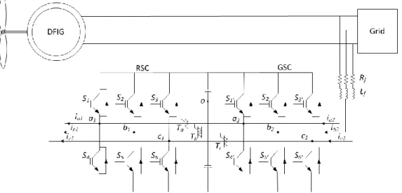
Fig. 2 shows the studied FTS. In this case, no redundant part (switch and driver) is used. Reconfiguration in the hardware (converter) is done by using bidirectional switches (TRIACs here), which makes possible to transform the converter structure from six to five-leg. In normal (pre-fault) operation of the converter, the converter is a conventional back-to-back and the three bidirectional switches are all open. Once a fault has been detected, the Fault Tolerant Control (FTC) switches on the suitable TRIAC to reconfigure the converter’s topology, and the converter stays in the 5-leg mode until the maintenance. Software reconfiguration is also necessary in PWM signal generation unit, to assure that proper gate signals are calculated and generated based on the actual structure, as will be explained later in this section.
Fig. 2. Studied fault-tolerant system.
There are different options for the bidirectional switches used in this structure. Any solid state bidirectional switch such as TRIACs, an IGBT associated to a diode bridge or common collector or common emitter connection of two IGBTs can be chosen [28]. In this study, TRIACs are used in order to remain cost-optimized.
It should be noted that the voltage producing capability in the five-leg converter is lower than in the six-leg converter. It means that with the same dc-link voltage, smaller three-phase voltages at the AC terminals can be produced, compared to the six-leg converter [27]. Also the current rating in the shared leg of the converter is larger than in the other legs. Therefore, when designing the fault-tolerant converter, careful considerations must be taken into account to have the desired performance after reconfiguration, either by increasing the dc-link voltage or by changing the control strategy to decrease the required voltages [24, 29-30]. A proper current rating of the shared leg has to be also consisdered. These studies can be found in an earlier contribution [27], where for a WECS with DFIG, different schemes for the minimization of the required dc-link voltage in post-fault mode are discussed.
C. Reconfigurable Control of the converter
Any conventional PWM method can be used for the control of the (pre-fault) six-leg converter. Upon the fault detection and reconfiguration, the faulty leg is disconnected by putting the two gate signals to zero, and one of the remaining healthy legs will be shared between the two sides of the converter. Among the several PWM approaches studied in the literature for this 5-leg post-fault topology, the method proposed in [23, 26] seems simpler for practical implementation, and also it produces less harmonics. Therefore this approach is adopted here. First, voltage reference signals 𝑣𝑥𝑖∗ (𝑥 𝜖{𝑎, 𝑏, 𝑐}, 𝑖𝜖{1,2}) for the two sides of the converter are calculated using the proper methods depending on the targeted applications. A Zero Sequence Signal (ZSS) is then added to these voltages to form the modulation signals. Adding a ZSS will not result in the change of the output line-to-line voltages, therefore it can be used as a degree of freedom to reduce the current harmonics and improve the dc-bus utilization. While different ZSS calculation methods are proposed in the literature, a few of them have gained wide acceptance. The most widely used ZSS for a three-phase system is calculated as below [31]:
𝑣𝑧𝑖(𝑡) = −1/2(𝑚𝑎𝑥(𝑣𝑎𝑖∗(𝑡) + 𝑣𝑏𝑖∗(𝑡) + 𝑣𝑐𝑖∗(𝑡)) + 𝑚𝑖𝑛(𝑣𝑎𝑖∗(𝑡) + 𝑣𝑏𝑖∗(𝑡) + 𝑣𝑐𝑖∗(𝑡))) (1)
where 𝑣𝑧𝑖 (𝑖𝜖{1,2}) is the ZSS for side “i”. This value is then added to the three voltage references to form the modified references:
𝑣𝑥𝑖(𝑡) = 𝑣𝑥𝑖∗(𝑡) + 𝑣𝑧𝑖(𝑡) (2)
The number of voltage references must be reduced from 6 to 5, to match the number of the post-fault converter legs. This reduction can be made by using an inverse lookup table [23]. In [29], this is realized by adding another level of ZSS addition corresponding to the converter configuration in the five-leg mode. As an exemple, assuming that the two legs “c” of the two sides are connected in the five-leg mode, the new voltage references are calculated by:
𝑣𝐴1= 𝑣𝑎1+ 𝑣𝑐2 ; 𝑣𝐵1= 𝑣𝑏1+ 𝑣𝑐2 𝑣𝐴2= 𝑣𝑎2+ 𝑣𝑐1 ; 𝑣𝐵2= 𝑣𝑏2+ 𝑣𝑐1
𝑣𝐶= 𝑣𝑐1+ 𝑣𝑐2
(3)
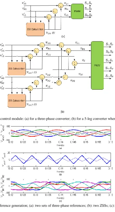
For each side of the converter, the same signal is added to all three reference values and therefore the fundamental output voltage will not be affected. Fig. 3 depicts the principle of PWM in this case. The ZSS addition for a three-phase converter (see
eq. (1), (2)) is shown in Fig. 3(a). This ZSS addition will be carried out for the two sets of voltage references at the two sides of the converter, and then by using (3) the final set of five voltage references will be calculated and sent to the PWM unit, as shown in Fig. 3(b). An example of five-leg voltage reference generation from two sets of three-phase voltage references is shown in Fig. 4.
Fig. 3. Principle of PWM control module: (a) for a three-phase converter; (b) for a 5-leg converter when the legs “c” are shared.
Fig. 4. Example of five-leg reference generation; (a): two sets of three-phase references; (b): two ZSSs; (c): resulted five-leg references.
D. Grid and Rotor side Voltage reference generation
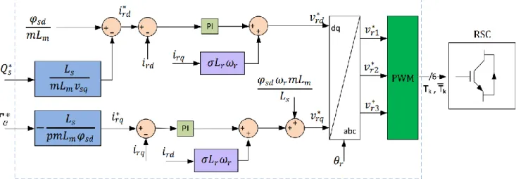
The control unit is responsible for the production of the voltage references to be used in the PWM blocs. Here, the voltage references for the grid side converter (GSC) and rotor side converter (RSC) are calculated based on the classical vector control strategies, similar to what is presented in [27], [32]. Control of RSC is especially important for the dynamic of the system. Fig. 5 shows the block diagram of the RSC control. Here 𝑄𝑠∗ is the reference for the stator reactive power, 𝑇𝑒∗ is the reference for electromagnetic torque of the DFIG, 𝜑𝑠 is the stator flux, and 𝑖𝑟 and 𝑣𝑟 are rotor current and voltage respectively. Subscripts ‘d’ and ‘q’ represent the variable in ‘d’ and ‘q’ coordinates of the Park transformation. 𝜔𝑟 is the rotor signals pulsation; 𝐿𝑠, 𝐿𝑚 and 𝐿𝑟 are total stator inductance, magnetizing inductance and total rotor inductance respectively [27]. The reconfigured voltage reference generation and PWM can be explained as the flowchart shown in Fig. 6, which uses the six voltage references for the six legs of the converter, and the fault’s location.
Fig. 5. Block diagram of the control of rotor voltages and currents.
Fig. 6. General form of the reconfigured voltage reference and PWM control signals generation.
Required changes in the references might be necessary since the voltage production capability of the five-leg converter is lower than that of the six-leg converter. For WECS with DFIG, it is shown in [27] that the required DC voltage can be decreased by careful consideration of the DFIG’s slip and reactive power production. However, in this study, the DC-link voltage is considered large enough to provide for the required voltages for both six and reconfigured five-leg converter, as this aspect has been already studied and published [27] and is not the main objective of this paper.
E. The reconfigurable control
The proposed reconfigurable control for the fault tolerant operation of the WECS is shown in Fig.7. Any convenient digital controller (e.g. DSP) may be used for the control and data acquisition purposes. Here, a dSPACE real-time control system is used. This type of controller is being widely used both in academic and industrial implementations thanks to its powerful control capabilities and ease of use that results in drastic reduction of prototyping time. The dSPACE is responsible of the production of the voltage references and PWM signals, and will change the PWM mode once a fault has been detected in the system.
On the other hand, the fault detection and compensation strategy must be carried out as fast as possible, to minimize the undesirable effects of the fault like discontinuities and transients on the system. Also it is very important for the monitoring and fault detection schemes to be performed in parallel with other control tasks. FPGAs have an inherently parallel structure and can execute all their tasks simultaneously by hardware implementation of the design [33]. This characteristic can lead to a drastic reduction in execution time [34]. Moreover, processing at logic level enables real-time monitoring and immediate compensation, which is essential in fault-tolerant applications. Hence, FPGA appears to be an excellent choice for the fault detection target in our application. It constantly monitors the system and upon fault detection sends the fault data to the dSPACE controller. The controller then switches from 6-leg to the proper 5-leg control mode. Moreover, gate signals are calculated by the dSPACE, but they are controlled directly by the FPGA, so the gate signals of the faulty leg are put to zero very quickly after the fault detection, and the effect of fault on the system can be minimized.
Fig.7. Proposed reconfigurable control.
F. Fault detection method
For open-circuit switch fault detection, the method of [16, 17] is used throughout this study. In this method, fault in each leg is diagnosed by comparing the measured and estimated pole voltages. Since, in reality, due to measurement and discretizing errors, the voltage error is not zero even during normal operation, two adjustments are employed to compensate for the effect of the measurement errors and delays to avoid false fault detection. Here, first the absolute value of the error between measured and estimated pole voltages is calculated. Then, this value is applied to a comparator with a threshold value ‘h’, to determine if the difference between the measured and estimated voltages is large enough to be considered as an error. Then, this signal is applied to an counter that computes the number of pulses while the output of the first comparator is high. The output of this up-counter corresponds to the time during which 𝑣𝑘𝑛𝑚 (measured voltage) and 𝑣𝑘𝑛𝑒𝑠 (estimated voltage) are different. Consequently, the fault occurrence is detected using simultaneously a “time criterion” and a “voltage criterion”. To do this, the up-counter output is applied to a second comparator with a threshold value of ‘N’. In this way, false fault detection due to semiconductor switching and inherent system delays is avoided and fault can be detected very fast. Fig. 8 shows the mentioned fault detection principle. The parameter h should be chosen to differentiate between normal and abnormal voltage readings, so it is fixed at Vdc/2. The parameter N should be chosen in such a way that NTc is larger than all delays in the control loop, where Tc.is the sampling period of the system. Here, the sampling period is chosen equal to 1 μs, corresponding to the FPGA operation frequency, i. e. 1 MHz. The same FPGA frequency is also used in the experimental set-up, as will be explained in Section III. Since in the experimental set-up the maximum total delay of the system is less than 10 μs, consequently N is chosen equal to 30, corresponding to NTc = 30 μs. The same value is used in both following simulations and experimental tests.
III. VALIDATION AND RESULTS
In order to verify the effectiveness of the proposed FTC, computer simulations and experimental tests are carried out. The results are presented and discussed in the following.
A. Simulation results
The system of Fig.2 and the associated FTC of Fig.7 are simulated in MATLAB/SIMULINK environment. Fixed step-size of 1 𝜇𝑠 is used in the simulations. Figs. 9 to 14 show the obtained results. First, an open-circuit fault is applied in 𝑆3 in RSC at t=2.5s. Voltage error (absolute value of u in Fig. 8) is given in Fig. 9. In normal operation of the converter, this error is visible only at the switching instants, while after fault occurrence, the error has a large value for a considerable duration. The output of the fault detection counter (Fig. 8) is proportional to the duration of this error, and is depicted in Fig. 10.
When the fault detection counter reaches the threshold value of N = 30 (i.e. 30 𝜇𝑠), the fault is declared, and the reconfiguration starts immediately. Fig. 11 shows the three-phase rotor currents. It can be verified that they are controlled effectively after reconfiguration. It should be noted that in order to evaluate the converter’s ability after reconfiguration, a step change in the reactive power reference of the WECS is applied at t=2.8 s. Stator active and reactive powers are shown in Fig. 12. The reconfigured system is capable of following the active and reactive references.
For an open-circuit fault applied in the GSC (𝑆3’ at t=2.5 s), other simulations are carried out. GSC currents before and after fault occurrence are provided in Fig. 13. It can be verified that the fault has had almost no effect on them. One can observe that the DC-link voltage is also perfectly controlled by the GSC after reconfiguration, as depicted in Fig. 14.
Fig. 9. Voltage error for a fault at RSC in S3′ at t=2.5 s
Fig.10. Fault detection counter for a fault in RSC in S3′ at t=2.5 s
Fig.11. Rotor currents for a fault in RSC in S3′ at t=2.5 s
Fig. 12. Stator active and reactive powers before and after fault occurrence and reconfiguration.
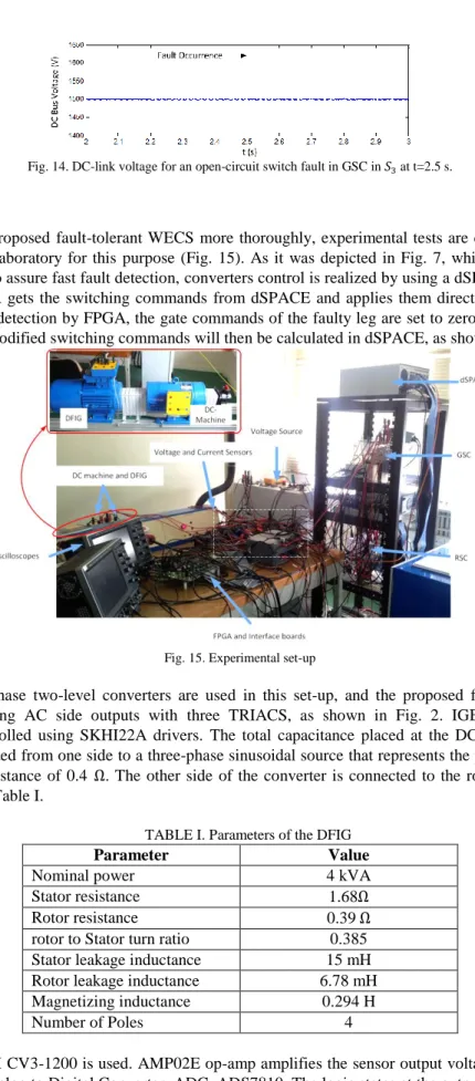
Fig. 14. DC-link voltage for an open-circuit switch fault in GSC in 𝑆3 at t=2.5 s.
B. Experimental results
In order to validate the proposed fault-tolerant WECS more thoroughly, experimental tests are carried out. An experimental set-up is developed in our laboratory for this purpose (Fig. 15). As it was depicted in Fig. 7, while the diagnosis algorithm is implemented on an FPGA to assure fast fault detection, converters control is realized by using a dSPACE real-time controller. In healthy operation the FPGA gets the switching commands from dSPACE and applies them directly to the converters. When a failure occurred, after fault detection by FPGA, the gate commands of the faulty leg are set to zero, and the fault information is fed back to dSPACE. The modified switching commands will then be calculated in dSPACE, as shown in Fig. 3.
Fig. 15. Experimental set-up
Two commercial three-phase two-level converters are used in this set-up, and the proposed fault tolerance is realized by connecting the corresponding AC side outputs with three TRIACS, as shown in Fig. 2. IGBTs are SKM50GB123D of SEMIKRON, and are controlled using SKHI22A drivers. The total capacitance placed at the DC-link is 2200 µF. The fault-tolerant converter is connected from one side to a three-phase sinusoidal source that represents the power grid, via a three phase inductance of 3mH and resistance of 0.4 Ω. The other side of the converter is connected to the rotor of the DFIG. The DFIG parameters are provided in Table I.
TABLE I. Parameters of the DFIG
Parameter Value
Nominal power 4 kVA
Stator resistance 1.68Ω
Rotor resistance 0.39 Ω
rotor to Stator turn ratio 0.385 Stator leakage inductance 15 mH Rotor leakage inductance 6.78 mH Magnetizing inductance 0.294 H
Number of Poles 4
For voltage sensors, LEM CV3-1200 is used. AMP02E op-amp amplifies the sensor output voltage. The measured voltage is then digitalized using an Analog to Digital Converter, ADC, ADS7810. The logic states at the output of the ADC are memorized during the conversion process using SN74HC174N D-type flip flops. In this experimental set-up, the maximum total system delay (delay of IGBT and driver, ADC, sensors, interface circuit, etc.) is less than 10 μs; therefore, as explained before, to avoid false FD, observation time is chosen equal to 30 μs to assure robust yet fast fault detection.
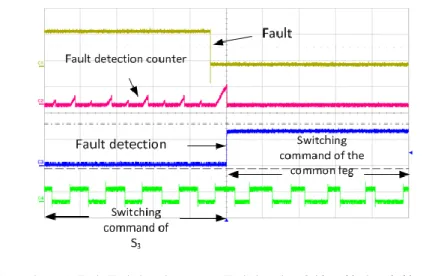
Stator active and reactive power references are set at 1kW and 0VAr, respectively. First, an open-circuit fault is applied on the “𝑆3′” switch of the GSC. DFIG slip has been equal to 20%. The open-circuit fault is realized through the control signal of the switch. Fig. 16 shows the GSC three-phase currents. Fault occurrence moment is visible in this figure (around t=4.94s). It can be verified that the AC currents are effectively controlled after fault detection and reconfiguration. Rotor currents are shown in Fig. 17 and it can be noted that they are not affected by the fault, so are the stator active and reactive powers, as shown in Fig. 18. DC-link voltage is also shown in Fig 19. All these results attest to the effectiveness of the proposed FTS. Fault detection signals are shown in Figs 20 and 21. It can be seen in Fig. 20 that the fault detection has been instantaneous, and the current of the faulty phase is well controlled after reconfiguration. Zoomed view of the detection signals are provided in Fig. 21. After reconfiguration, switching commands of the common-leg are determined based on the 5-leg PWM method, therefore the command of 𝑆3’ is changed after reconfiguration.
Fig.16. GSC currents for a fault in 𝑆3’.
Fig.17. Rotor currents for a fault in 𝑆3’.
Fig.18. Stator active and reactive powers for a fault in 𝑆3’.
Fig.19. DC-link voltage for a fault in 𝑆3’.
Fig.21. Fault detection for an open-circuit switch fault in 𝑆3′ from (top to bottom): Fault signal, Fault detection counter, Fault detection, 𝑆3′/shared leg’s switching command- Time scale: 100µs/div.
For an open-circuit switch failure applied in 𝑆3 in the RSC, rotor currents are shown in Fig. 22. They are also perfectly controlled after reconfiguration. This is also true for active and reactive powers and DC-link voltage, as shown in Figs 23 and 24. Fault detection signals are shown in Figs 25 and 26. Faulty phase current and the current of the TRIAC 𝑇𝑐 (see Fig. 2) are shown in Fig. 25. Zoomed view of the fault detection signals are provided in Fig. 26. As it was expected, fault is detected in 30 𝜇𝑠.
Fig. 22. Rotor currents for a fault in 𝑆3.
Fig. 23. Stator active and reactive powers for fault in 𝑆3.
Fig. 24. DC-link voltage for fault in 𝑆3.
Fig. 26. Fault detection for 𝑆3 (top to bottom): Fault, Fault detection counter, Fault detection, 𝑆3/shared leg’s switching command – Time scale: 100𝜇s/div.
IV. CONCLUSION
In this paper, a fault-tolerant scheme for a WECS based on DFIG is proposed. Using three additional bidirectional switches (TRIACs in this study), the back-to-back converter of the DFIG can continue to operate after an open-circuit failure in one of the switches. Fault detection must be very fast; therefore an FPGA-based method is used for this purpose. However, WECS’s control can be implemented on a software-based digital target. Upon fault detection, appropriate changes must take place in software and hardware of the system. Topology reconfiguration is carried out using the three additional TRIACs. Software changes are based on a specific PWM method with double zero sequence signal injection, and use the fault’s information delivered by the FPGA to the processor. An experimental set-up is specially built for this study, and a dSPACE is used for the control. Experimental results are in accordance with simulation ones, and testify to the effectiveness of the proposed fault-tolerant WECS. The proposed FTS is capable of quickly detecting the open-switch failure and isolating it, so that the other parts of the system are not affected by the anomalies related to this fault. By making the necessary reconfiguration in the hardware and software parts of the WECS, it is possible to continue to produce for electricity after fault occurrence. All voltages, currents and powers are efficiently controlled after reconfiguration. Then, the reliability of the whole WECS is highly improved.
REFERENCES
[1] U. Falko, R. Brecha, and G. Luderer, "Analyzing major challenges of wind and solar variability in power systems", Renewable Energy, Vol. 81, pp. 1 - 10, September 2015.
[2] Tohidi, S., P. Tavner, R. McMahon, H. Oraee, M. R. Zolghadri, S. Shao, and E. Abdi. "Low voltage ride-through of DFIG and brushless DFIG: Similarities and differences." Electric Power Systems Research, vol. 110, pp. 64-72, 2014.
[3] Hang, Jun, Jianzhong Zhang, and Ming Cheng. "Fault diagnosis of wind turbine based on multi-sensors information fusion technology." IET Renewable Power Generation, Vol.8, Iss. 3, pp. 289-298, 2014.
[4] S. Fengming and R. Patton, "An active fault tolerant control approach to an offshore wind turbine model" Renewable Energy, Vol. 75, pp. 788 -798, 2015 [5] Djurovic, S., et al. "Condition monitoring of wind turbine induction generators with rotor electrical asymmetry." IET Renewable Power Generation Vol. 6,
Iss. 4, pp. 207–216, 2012.
[6] Chen, Bindi, Peter C. Matthews, and Peter J. Tavner. "Automated on-line fault prognosis for wind turbine pitch systems using supervisory control and data acquisition." Renewable Power Generation, IET, Vol. 9, Iss. 5, pp. 503–513, 2015.
[7] Gritli, Yasser, Andrea Stefani, Claudio Rossi, Fiorenzo Filippetti, and Abderrazak Chatti. "Experimental validation of doubly fed induction machine electrical faults diagnosis under time-varying conditions." Electric Power Systems Research, vol. 81, no. 3, pp.751-766, 2011.
[8] Vilchis-Rodriguez, Damian S., Sinisa Djurovic, and Alexander C. Smith. "Wound rotor induction generator bearing fault modelling and detection using stator current analysis." Renewable Power Generation, IET Vol. 7, Iss. 4, pp. 330–340, 2013.
[9] A. Yazdani, H. Sepahvand M. Crow and M. Ferdowsi, "Fault Detection and Mitigation in Multilevel Converter STATCOMs", Industrial Electronics, IEEE Transactions on, Vol. 58, No. 4, pp. 1307 - 1315, 2011.
[10] P. Lezana, R. Aguilera, and J. Rodriguez, "Fault detection on multicell converter based on output voltage frequency analysis", Industrial Electronics, IEEE Transactions on, Vol. 56, No. 6, pp. 2275 - 2283, 2009.
[11] M. A. Rodríguez-Blanco, A. Claudio-Sánchez, D. Theilliol, L.G. Vela-Valdés, P. Sibaja-Terán, L. Hernández-González, J. Aguayo-Alquicira, "A Failure-Detection Strategy for IGBT Based on Gate-Voltage Behavior Applied to a Motor Drive System", Industrial Electronics, IEEE Transactions on, Vol. 58 , No. 5, pp. 1625 - 1633, 2011.
[12] T.A. Najafabadi, F.R. Salmasi, P. Jabehdar-Maralani, "Detection and Isolation of Speed- DC-Link Voltage and Current-Sensor Faults Based on an Adaptive Observer in Induction-Motor Drives", Industrial Electronics, IEEE Transactions on, Vol. 58, No. 5, pp. 1662 - 1672, 2011.
[13] S. Cruz, M. Ferreira, A. Mendes, and A. J. M. Cardoso, "Analysis and Diagnosis of Open-Circuit Faults in Matrix Converters," Industrial Electronics, IEEE Transactions on, Vol. 58, No.5, pp. 1648 - 1661, May 2011.
[14] Kamel, Tamer, Yevgen Biletskiy, and Liuchen Chang. "Fault diagnosis and on-line monitoring for grid-connected single-phase inverters." Electric Power Systems Research, vol. 126, pp. 68-77, 2015.
[15] Meradi, S., K. Benmansour, K. Herizi, M. Tadjine, and M. S. Boucherit. "Sliding mode and fault tolerant control for multicell converter four quadrants." Electric Power Systems Research, vol. 95, pp. 128-139, 2013.
[16] M. Shahbazi,E. Jamshidpour, P. Poure, S. Saadate, M. R. Zolghadri, “Open and Short-Circuit Switch Fault Diagnosis for Non-Isolated DC-DC Converters Using Field Programmable Gate Array”, IEEE Trans. on Industrial Electronics, Vol. 60, no. 9, pp. 4136 - 4146, Sep. 2013.
[17] M. Shahbazi, P. Poure, S. Saadate, M. R. Zolghadri, “FPGA-based Fast Detection with Reduced Sensor Count for a Fault-Tolerant Three-Phase Converter”, IEEE Trans. on Industrial Informatics, Vol. 9, no. 3, pp. 1343 - 1350, Aug 2013.
[18] D.U. Campos-Delgado, D.R. Espinoza-Trejo, and E. Palacios, "Fault-tolerant control in variable speed drives: a survey," IET Electric Power Applications, Vol. 2, No.2, pp. 121 - 134, Mar 2008.
[19] C. B. Jacobina, R.L. de Araujo Ribeiro, A.M.N. Lima and E.R.C. da Silva, "Fault-tolerant reversible AC motor drive system," Industry Applications, IEEE Transactions on, Vol. 39, pp. 1077 - 1084, Jul-Aug 2003.
[20] Ibarra, Edorta, Jon Andreu, Iñigo Kortabarria, Enekoitz Ormaetxea, Iñigo Martínez de Alegría, José Luís Martín, and Pedro Ibañez. "New fault tolerant matrix converter." Electric Power Systems Research vol. 81, no. 2, pp. 538-552, 2011.
[21] S. Karimi, P. Poure and S. Saadate; “FPGA-based fully digital fast power switch fault detection and compensation for three-phase shunt active filters”; Electric Power Systems Research vol. 78 no. 11, Nov., pp. 1933–1940, 2008.
[22] M. Shahbazi, P. Poure, S. Saadate, M. R. Zolghadri, "FPGA-based reconfigurable control for fault-tolerant back-to-back converter without redundancy", IEEE Trans. on Industrial Electronics, Vol. 60, no. 8, pp. 3360 - 3371, Aug 2013.
[23] A. Bouscayrol, B. Francois, P. Delarue and J. Niiranen, "Control implementation of a five-leg AC-AC converter to supply a three-phase induction machine", Power Electronics, IEEE Transactions on, Vol. 20, pp. 107 - 115, Jan 2005.
[24] K. Oka, Y. Nozawa, R. Omata, K. Suzuki, A. Furuya, K. Matsuse, "Characteristic comparison between five-leg inverter and nine-switch Inverter", Power Conversion Conference (PCC ’07), Nagoya, pp. 279 - 283, 2007.
[25] M. Jones, S.-N. Vukosavic, D. Dujic, E. Levi, P. Wright, "Five-leg inverter PWM technique for reduced switch count two-motor constant power applications", IET Electr Power App, pp. 275 - 287, 2008.
[26] C.-B. Jacobina, R. Ribeiro, A. Lima, E. Da Silva, "Fault-tolerant reversible AC motor drive system", IEEE Trans Ind Appl., vol. 39, pp. 1077 - 1084, 2003 [27] M. Shahbazi, P. Poure, S. Saadate, M.R. Zolghadri, "Five-leg converter topology for wind energy conversion system with doubly fed induction generator",
Renewable Energy, Vol. 36, No. 11, pp. 3187 - 3194 November 2011.
[28] S.-W. Wheeler et al. "Matrix converters: a technology review." Industrial Electronics, IEEE Transactions on, Vol.49, no. 2, pp. 276 - 288, 2002
[29] M. Jones, et al., "Five-leg inverter PWM technique for reduced switch count two-motor constant power applications," IET Electric Power Applications, Vol. 2, No.5, pp. 275 - 287, Sep 2008.
[30] M. Jones, D. Dujic and E. Levi, "A performance comparison of PWM techniques for five-leg VSIs supplying two-motor drives," IECON 2008, pp. 508 - 513, 2008.
[31] K. Zhou, and D. Wang, "Relationship between space-vector modulation and three-phase carrier-based PWM: a comprehensive analysis [three-phase inverters]." IEEE Transactions on Industrial Electronics, Vol 49, no. 1, pp. 186 - 196, 2002.
[32] Zamanifar, M., B. Fani, M. E. H. Golshan, and H. R. Karshenas. "Dynamic modeling and optimal control of DFIG wind energy systems using DFT and NSGA-II." Electric Power Systems Research vol. 108, pp. 50-58, 2014.
[33] Valtierra-Rodriguez, Martin, Roque Alfredo Osornio-Rios, Arturo Garcia-Perez, and Rene de Jesus Romero-Troncoso. "FPGA-based neural network harmonic estimation for continuous monitoring of the power line in industrial applications." Electric Power Systems Research 98 (2013): 51-57.
[34] E. Monmasson, L. Idkhajine, M. N. Cirstea, I. Bahri, A. Tisan, and M. W. Naouar, "FPGAs in Industrial Control Applications" Industrial Informatics, IEEE Transactions on, No. 99, pp. 1-1, 2011.