VIST ALPINE BINDING
TECHNICAL MANUAL 2006/07
Installation and service manual
for retailers
3
Contents
Introduction 4
1 Technical description of VIST
components 5
1.1 X-Key Bindings 5
1.2 X-Key Demotype bindings 5 2 Accessories and checks for
installation of bindings 7
2.1 Drilling jigs 7
2.2 Other accessories needed
for mounting 7
2.3 Preparation and checking
of all components 8
3 Mounting the bindings 10 3.1 Mounting VIST X-Key bindings
directly on skis or on a plate that
is not predrilled 10 3.2 Particular mounting situations 12 3.3 Mounting VIST Demotype
Universal bindings 12 4 Adjusting the binding 14
4.1 Adjusting the toe-piece height
of X-Key bindings 14
4.2 Micrometric toe-heel size and
pressure adjustment for X-Key bindings 15 4.3 Micrometric toe-heel size and
pressure adjustment for Demotype
range of bindings 15
5 SPEEDLOCK® system
mounting instructions 16
5.1 Speedlock TT 16
5.2 Speedlock PRO/RACE 18 6 Defining and adjusting the release
settings 23
6.1 Identifying the adjustment setting with the VIST Adjustment Chart 23 6.2 Adjusting the release settings 24 7 Checking procedure: possible
problems and solutions 25 7.1 Testing the lateral elasticity
of toe-piece 25
7.2 Testing the vertical elasticity
of heel-piece 25
7.3 Mechanical testing of registered
release settings 25
Section Page
8 Rental and Demo Testing 27 8.1 Pre-Season Binding Inspections 27 8.2 In-Season Inspections 27 9 Warranty and limitation of liability 29
9.1 Dealing with Skiers with release or Retention Concerns 29 9.2 Retail Inspection Procedures and
Trouble Shooting 30
9.3 Rental Inspection Procedures and
Trouble Shooting 32
9.2 Special Circumstances 32 10 Service shop practices 33 10.1 Servicing and warranty 33 10.2 Record keeping 35 10.3 Skier instructions 37 10.4 Accidents and injuries 39
11 Sample forms 40
11.1 Warning and Liability Release 40 11.2 Warning and Release For
Non-Recommended
Release/retention Settings 41 11.3 Warning and Release For
Servicing Old equipment 42 11.4 Information For Skiers
requesting discretionary Settings 43 11.5 Post Accident Ski Inspection
report 44
12 VIST authorized dealer information 45 12.1 Indemnification 45 12.2 VIST certified technicians 47 12.3 How to handle a legal claim 48
13 Glossary 49
VIST Certified Technician
Certification Test 50 VIST Certified Test
Answer Sheet 53
VIST Binding Adjustment Chart 54
Mounting and service manual for dealers. This technical manual is published by VIST to provide information for VIST North America authorized dealers regarding the installation, adjustment and servicing of VIST alpine ski bindings. Please call VIST North America Customer Service at 866.900.8478 if you have any questions for which you cannot find a clear answer in this manual or send an e-mail to: [email protected]
VIST bindings have been designed and manufactured to meet the latest technology and conform to all applicable American and international standards.
VIST bindings have been designed to provide maximum performance and convenience when used in conjunction with skis & plates. These three products are designed to work together to maximize the skier’s experience on the snow as well as easier and quicker mounting in the shop. Although designed as part of an integrated system, VIST bindings, skis and boots are compatible with all products that meet current ASTM and ISO standards. The exclusive use of original VIST materials will enable you to offer excellent service, which is easier to carry out and saves time and energy. This manual covers the most important aspects of mounting, care and maintenance of VIST bindings to enable you to offer your customers VIST products and premium assistance.
Please read this manual carefully. This manual states the only procedures that are
recommended by VIST for the installation, adjustment and servicing of VIST bindings. Making technical modifications to bindings or failing to follow the procedures in this manual will void all warranties on the product and render your shop ineligible for indemnification from VIST in the event of a legal claim. A copy of this manual should be kept in the workshop, and another copy should be filed for future reference.
5
1.0 Technical description of
VIST binding components
- X-Key V614 - X-Key V412 - X-Key V311
Fig. 1a / 1b - Fig. 2
A.Toe-piece release setting adjustment screw (Z setting)
B.Toe-piece release value adjustment indicator (Z setting)
C.Anti-friction plate (DIR) /
C*. New Anti-friction device (fixed plate)
D.Heel-piece release value adjustment screw (Z setting)
E. Elastic recovery rear screw
F. Heel-piece release value adjustment indicator (Z setting)
G.Ski brake fixing screw
H.Heel-piece lever
I. Heel pressure indicator notch
J. Ski brake fixing notches
K.Ski brake rods
1.1
X-Key Bindings
A C* BFig. 1b
A C BFig. 1a
Fig. 2
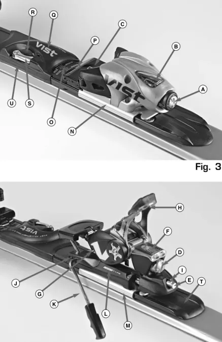
I E K G J D F H- X-Key V412 Demotype Universal - X-Key V311
Demotype Universal
Fig. 3 - Fig, 4
A. Toe-piece release setting adjustment screw
B. Toe-piece release setting adjustment indicator
C. Anti-friction plate
D. Heel-piece release setting adjustment screw
E. Elastic recovery rear screw
F. Heel-piece release setting adjustment indicator
G. Ski brake fixing screw
H. Heel-piece lever
I. Heel pressure indicator notch
J. Ski brake fixing notches
K. Ski brake rods
L. Demotype label
M.Rear aluminium slide
N.Front aluminium slide
O. Size adjustment scale
P. Size adjustment indicator
Q. Central cover
R. Locking lever/unlocking device
S. Metal safety lever
T. Base plate
U. Mid-way reference for mounting
1.2
X-Key Demotype bindings
Fig. 3
Fig. 4
P A B C Q R O N S U H T M L K G J I E D F7
2.0 Accessories and checks
for installation of bindings
2.1.1 Generic drilling jig for bindings X-Key V311, X-Key V412 and X-Key V614 (Fig. 5) A.Fixing clamps control levers
B.Fixing clamps
C.Size adjustment lever
D.Holes for heel-piece
E. Holes for toe-piece
G. Reference line for mounting
H.Sole length graduated scale in mm The drilling jig was specifically made for mounting VIST Demotype bindings on the majority of skis found on the market. The jig is adjusted according to the length of the sole of the boot to be used with the bindings.
2.1.2 Drilling jig for Demoplate Univ. bindings X-Key V311, X-Key V412 (Fig. 6) A.Fixing clamps control levers
B.Fixing clamps
C.Reference line for mounting
The drilling jig was specifically made for mounting VIST Demotype bindings on the majority of skis found on the market.
The following items are required for mounting: - Electric drill
- Electric screwdriver with adjustable torque. Use Pozidrive (PZ) No.3 type tools. Philips (PH) cross-head screwdrivers are not suitable for normal ski binding screws because their different shape could damage the screws. - Ski clamp
- Pozidrive screwdriver (PZ) No.3 - VIST jig for bindings (MA07)
- 4.1/9 mm or 3.5/7 mm drilling bit. - Waterproof marking pen
Attention: do not use any type of glue when mounting the bindings.
Attention: Only use original VIST screws. If some screws are missing, call the VIST Customer Service (number: 866.900.8478)
2.1
Drilling jigs
2.2
Other accessories needed for
mounting
Fig. 5
Fig. 6
A C F G H E E E E B B A D A B B A CGUIDELINES FOR INSPECTION OF SKI BINDINGS
1. Every VIST binding complies with or exceeds the requirements of all ASTM or ISO
standards for bindings at the time of design and manufacture.
2. Whenever work is carried out on VIST bindings, they should be inspected and checked. This is especially important when bindings that have already been used are to be fitted.
3. The ski/binding/boot system must be inspected and tested each time any component is adjusted, replaced or repaired.
Check the bindings as described below 1. Check that the DIN adjustment range is
suitable for the user.
2. Check the interface surfaces with the boot: if there are signs of excessive wear or damage, repair or replace the component.
3. Check the anti-friction plate: it must not show signs of wear and there must be no missing parts.
4. Check that the ski brake arms are not broken or bent, that they retract fully when the boot is inserted and that the spring is strong enough to easily support the weight of the ski resting on a flat surface.
5. Check that there are no missing or damaged screws.
6. Check that the indicators and graduated scales are clearly legible.
7. All surfaces must be clean. Check that there are no signs of corrosion, rust or dirt in general. Clean the binding with a damp cloth or compressed air.
Do not use solvents to clean the bindings.
Do not use silicones or other types of lubricant.
2.3
Preparation and checking of all
components
Fig. 7
Fig. 8
TIP OF SKI BOOT9 to make them conform to the standards. If
the boot can be modified to make it comply with ISO standards, then it can be used with VIST bindings.
2. Check the height and width of the sole in the areas which come into contact with the binding. Make sure that the sole is perfectly flat.
3. Inspect the contact area with the
anti-friction plate: the sole must not show signs of damage or excessive abrasion; it must be flat and smooth.
4. Check that there are no signs of excessive abrasion on the sole in all areas which come into contact with the binding. The sole must not be worn beyond the minimum dimensions specified in the standards. If in doubt, it is preferable to replace the boot. 5. Nothing which may interfere with normal
functioning of the binding must be inserted between the sole/binding interface.
6. Boots with thermoplastic rubber soles and, in particular, boots designed for ski
mountaineering, are not suitable because they could prevent correct functioning of the binding.
7. Check whether the boot is an adult or children’s model. Boots that according to the standards are defined as children’s boots, must not be used with VIST adult bindings.
(Please refer to figures 7 and 8 for the sole dimensions required for VIST bindings). Note: All dimensions have a tolerance of +/- 1 mm.
GUIDELINES FOR INSPECTION OF SKIS 1. In general, all skis are designed (in
accordance with ISO standards) with suitable reinforcement in the binding mounting area. Nevertheless, there may be differences in the materials used or in ski geometry: You should therefore always follow the instructions supplied by the ski manufacturer regarding the best procedure for installing bindings.
2. Always follow the ski manufacturer’s instructions regarding the size of drill bit to be used. In the absence of such
instructions, follow the instructions below:
Check the skis as described below
1. Check that the ski is thick enough to take the binding fixing screws. Once the binding has been fitted, the screws must not pierce or distort the base of the ski. If you suspect that the ski might be too thin, position the binding component so that the screw hangs down alongside the edge of the ski. If you think the screw might project beyond the base, use shorter screws or very carefully, shorten the existing screws. Take great care when assembling children’s skis. 2. Check the width of the ski: if the ski is too
narrow, the screws could cause splitting or distortion of the ski.
GUIDELINES FOR INSPECTION OF SKI BOOTS 1. VIST bindings must be used with boots
manufactured in accordance with the following standards: ISO 5355, DIN 7880, ASTM F944.
These standards define the critical profiles of the boot toe and heel to ensure total compatibility with the binding.
2. When fitting and adjusting bindings, the boots that will actually be used by the skier must be used as the reference.
Check the boots as described below
1. If the boot conforms to standards, it must be stamped with the ISO or DIN mark. If no such marking is present on the boot, contact the manufacturer to obtain the correct procedure for modifying the boots
3.0 Mounting the bindings
If you want to mount VIST X-Key on skis directly or on a plate that is not predrilled, you must use the specific drilling jig (Fig. 5).
Note: do not carry out the following procedure on skis with VIST perforated plate.
3.1.1 Adapting the jig to the length of the boot: 1. Open the locking lever of the jig (Fig. 5, C)
and pull its mobile part outwards.
2. Place the boot on the jig then press the mobile part against the end of the boot and close the locking lever.
3. Should the boot not be available, adjust the jig according to the length of the sole of the boot (Fig. 9), referring to the graduated scale (in mm) found on the jig (Fig. 5, H).
3.1.2 Drilling the ski:
1.Fit the skis in the vice and place the mid-way mark of the jig according to the instructions of the ski manufacturer. Always check that the jig adheres perfectly to the surface of the ski/plate.
2.Place the boot on the jig again, and make sure that it fits tightly (and cannot move) between the front and rear part of the jig. For the mounting position of the binding, refer to the boot’s mid-way sole positioning indicator found on the ski.
3. Drilling: follow the instructions of the ski manufacturer with regards to diameter and depth of the hole. In case of doubt, you must always use the shortest and thinnest bit first (3.5/7mm), and then if necessary use a bigger bit.
4.Cleaning: after you have finished drilling, open the vice, turn the ski over and hit it on the base with the palm of your hand to make the shavings fall out. Fit the ski in the vice again, then pour some detergent on a piece of paper or a cloth and clean the surface of the ski (use only a minimum quantity of detergent in order to prevent it from going into the holes).
Attention:do not use any type of glue when mounting the bindings.
Note: the bindings manufacturer shall in no way be liable for any damage caused to the skis when the bindings are being mounted.
3.1
Mounting VIST X-Key bindings
directly on skis or on a plate
that is not predrilled
Fig. 9
11
3.1.3 Mounting the toe-piece of X-Key bindings: 1.Fit the anti-friction plate in the housing of the
toe-piece (if the toe-piece has the new Anti-friction device, it is already fixed), place them both on the plate in such a way as to make the four toe-piece screws correspond to the holes on the ski/plate.
2.Screw each of the other four screws of the toe-piece 1-2 turns using the electric screwdriver with Pozidriv (PZ) No.3 drill bit, then check if the binding is placed properly. Finish screwing on all screws and then check the tightness (Fig. 10)with the manual Pozidriv (PZ) No.3 screwdriver.
3.1.4 Mounting the heel-piece of X-Key: Attention:when mounting, the heel-piece must be closed, i.e. with the lever turned upwards.
1. Place the heel-piece on the ski/plate in such a way that the screws are aligned with the hole made beforehand.
2. Screw all four screws 1 or 2 turns with the electric screwdriver and check positioning. Finish screwing on the screws and then check the tightness (Fig. 11) with the manual Pozidrive (PZ) No.3 screwdriver.
Attention:make sure you hold the screwdriver vertically (perpendicular to the surface of the ski) when screwing on the rear screws of the heel-piece. We recommend that you do not force the plastic housings of the screws sideways in order to prevent the plastic from breaking or deforming.
3.1.5 Mounting the ski brake:
1. Place the two metal notches on the front part of the brake (Figure 1, J) in their housing on the base of the heel-piece (Fig. 12).
2. Turn the brake backwards and tighten the screw with the manual Pozidriv (PZ) No.3 screwdriver (Fig. 13).
3. Check if the two rods (Figure 1, J) can move freely along the sides of the ski.
Note: the brake can only be mounted on skis with a maximum width of 74 mm.
For skis wider than 74 mm width ask for VIST wide ski brake (cod. VK-WBRAKE). For skis wider than 100 mm width ask for VIST XL wide ski brake.
Note: never press the brake before mounting it.
Fig. 11
Fig. 12
If the boots are too large or too small in respect to the mounting jig, proceed as follows:
1. Place the boot on the ski in such a way that the mid-way sole indicator corresponds with the corresponding mark found on the ski.
2. Clearly mark (on the ski) the position of toe and heel of the boot. There are some slits on the jig (at area of toe and heel of the boot) from which you can see the surface of the ski.
Attention: as the holes in this case are drilled out of the area normally used for mounting the binding, you must measure the thickness of the ski in order to check that the tip is not too long. Ski thickness must be at least 11mm, to prevent the drill bit from perforating the ski from side to side, thus permanently damaging it.
Note: the bindings manufacturer shall in no way be liable for any damage caused to the skis when the bindings are being mounted. 3. Place the jig on the ski in such a way that
the slit on it (corresponding with the toe of the boot) matches the mark made on the ski. Only drill holes for the toe-piece. 4. Place the jig on the ski in such a way that
the slit on it (corresponding with the heel of the boot) matches the mark made on the ski. Only drill holes for the heel-piece. 5. Continue with the mounting as described in
paragraph 3.1.
Attention: do not use any type of glue when mounting the bindings.
3.2
Particular mounting situations
VIST Demotype Universal bindings have been designed to be mounted exclusively on skis with a flat profile.
3.3.1 Drilling the ski
To ensure correct alignment of the binding, you must use the specific drilling jig for the
Demotype Universal version (MA06) to drill the ski (Fig. 6).
1. Open the clamps (Fig. 6, B) turn the two levers (Fig. 6, A) and place the jig in the right direction (check the instructions on the labels).
2. Move the jig until the midways of the jig
(Fig. 6, C) and the ski are aligned. Check that the jig adheres completely to the ski. Moreover, check that the clamps are firmly in contact with the sides of the ski.
3. Drilling: follow the instructions of the ski manufacture with regards to diameter and depth of the hole. In case of doubt, you must always use the shortest and thinnest bit first (3.5/7mm), and then if necessary use a bigger bit.
Attention:do not use any type of glue when mounting the bindings.
Note: the bindings manufacturer shall in no way be liable for any damage caused to the skis when the bindings are being mounted.
3.3.2 Mounting the base plate
1. Take the demo plate out of the box, unlock the adjustment device and place the
aluminium slides as near as possible to each other (size indicator at 260 mm) (Fig. 14).
2. Place the plate in the right direction on the ski and move it until the mid-way of the ski and the plate are aligned. Then check if the housings of the screws perfectly correspond to the holes drilled on the jig beforehand.
3. Take the two steel bushings out of the nylon bag and fit them in the two housings nearest the tip of the plate, then fit the eight screws in the corresponding holes/bushings (Fig. 14).
4. Fasten the screws: with regards to the tor-que (N/m), follow the instructions of the ski manufacturer.
3.3
Mounting VIST Demotype
Universal bindings
13
Fig. 16
Fig. 17
Fig. 18
Fig. 19
Fig. 15
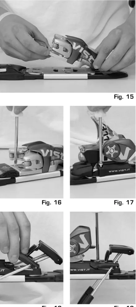
3.3.3 Mounting the toe-piece of X-Key bindings: 1. Fit the anti-friction plate in the specific housing
of the toe-piece, placing them both on the front aluminium slide in such a way as to align the screws to the holes of the plate (Fig. 15).
2. With the electric screwdriver equipped with Pozidrive (PZ) bit No.3, make the screws of the toe-piece turn 1-2 times each then check if the binding is positioned correctly. Finish screwing on all the screws then with the manual Pozidrive (PZ) No.3 screwdriver, check the tightness (Fig. 16).
Attention: maximum closing torque 4 N/m.
3.3.4 Mounting the heel-piece bindings X-Key Attention:when mounting, the heel-piece must be closed, i.e. with the lever turned upwards.
1. Place the toe-piece on the aluminium slide in such a way that the screws are aligned with the holes.
2. With the electric screwdriver make all four screws turn 1-2 turns and check the positioning. Finish screwing on the screws then with the manual Pozidrive (PZ) No.3 screwdriver; check the tightness (Fig. 17).
Attention:maximum closing torque 4 N/m.
Attention:make sure you hold the screwdriver vertically (perpendicular to the surface of the ski) when screwing on the rear screws of the heel-piece. We recommend that you do not force the plastic housings of the screws sideways in order to prevent the plastic from breaking or deforming.
3.3.5 Mounting the ski brake
1.Fit the two metal notches found on the front part of the brake (Fig. 2, J)in the specific housing on the base of the heel-piece (Fig. 18).
2.Turn the brake backwards and screw on the screws with the Pozidrive (PZ) No.3
screwdriver (Fig. 19).
3.Check if the two rods (Fig. 2, K) can move freely along the sides of the ski.
Note: the brake can only be mounted on skis with maximum width of 74mm.
For skis wider than 74 mm width ask for VIST wide ski brake (cod. VK-WBRAKE). For skis wider than 100 mm width ask for VIST XL wide ski brake.
Fig. 20
Fig. 22
Fig. 21
Fig. 23
4.0 Adjusting the binding
General instructions:
The applicable standards for adjustments to ski bindings are the international standards, and therefore for legal purposes (product
responsibility) any adjustments must be carried out in strict conformity with the international standards. In case of doubt always contact the organisations responsible for conformity of standards. All the adjustments that are not in conformity with the aforementioned standards are the responsibility of the persons (dealers or consumers) who have carried out such
adjustments. Avoid carrying out adjustments that are not in conformity, in particular avoid: - Adjusting settings that are higher than visual
indicator setting Z-10 (red zone).
- Use with ski boots that have soles in thermo-plastic, such as alpine touring ski boots. Important warnings: Adjustment and maintenan-ce of the bindings must be carried out by a specialised dealer according to the instructions included in the manufacturer’s technical manual. The adjustment of the release functions should always be checked by specialised personnel with special certified equipment. Adjustment and control of correct functioning of the bindings must be carried out again every time the bindings are removed and mounted on the same skis or mounted on skis other than those on which they were previously mounted (even if their setting was correct) insofar as during the
detachment-mounting operations the balance of the ski-binding-boot function system could change and thus the release setting may be modified.
Attention:The boot and binding constitute a function unit therefore never replace or modify the individual components without re-adjusting and controlling the release setting.
4.1
Adjusting the toe-piece height of
X-Key bindings
A special spring housed in the toe-piece of X-Key bindings ensures automatic toe-piece height adjustment when the boot is fitted into the binding.
Never carry out manual adjustments.
Attention:Check that the sole is not excessively scratched in all the parts in contact with the binding. The sole must not be worn out to the extend that goes over the minimum
requirements established by the standards.
15 versus each other; a click will let you know
that the system is fully locked. Check that the red graph on the lever has fully disappeared under the metal safety lever (Fig. 22).
6.Close the binding with the fitted boot.
7. Check the position of the rear screw of the elastic recovery device: the correct adjust-ment is reached when the head of the screw corresponds (approx. 2 mm with the notch on the base of the toe-heel, Fig. 24 for X-Key Demotype).
Attention:never change the position of the rear elastic recovery screw for any reason
whatsoever as it would compromise the setting of the size adjustment indicator, and
consequently, the release loads.
Fig. 24
4.3.2 An alternative adjustment procedurecan be carried out as follows: 1. See point 1 of previous chapter.
2. Read the length of the sole of the boot found on the base of the heel area (in mm).
3. With both hands move the toe-piece and heel-piece until the size indicator (Fig. 3, P)
(connected to the toe-piece) reaches the position on the graduated scale (Fig. 3, O)
nearest to the length required (Ex. Sole length 312= indicator on 310, sole length 314= indicator on 315).
4. See point 4 of previous chapter.
5. See point 5 of previous chapter.
6. See point 6 of previous chapter.
7. See point 7 of previous chapter.
Attention: never change the position of the rear elastic recovery screw for any reason whatsoever as it would compromise the setting of the size adjustment indicator.
1. Fit the boot in the binding then close the binding.
2. Turn the screw on the rear of the toe-heel
(Fig. 2, E)until the screw head is aligned with the reference notch on the base of the toe-heel (Fig. 2, I). (Fig. 20).
3. Open and then close the binding to check if the adjustment is precise. If the head of the screw does not match perfectly with the refe-rence notch, repeat point 2.
- Boots that according to regulations are defined as children’s boots must not be used with VIST adult bindings.
4.2
Micrometric toe-heel size and
pressure adjustment for X-Key
bindings
The Demotype range of bindings are equipped with a new quick size-adjustment system.
By simply moving the central lever (Fig. 21, 22)
this system adjusts the size of the binding based on the length of the sole. The boot remains locked on the correct mid-way of the ski, always and for all sizes.
The Demotype binding can accommodate all types of soles with a length ranging from 260 mm to 365 mm.
4.3.1 The quickest and easiest way to adjust the size is as follows:
1. Unlock the system (Fig. 21) with the metal safety lever and turning the central lever to SET (red: the binding is not ready for skiing).
2. Place the boot between the toe-piece and heel-piece (with heel-piece open, Figure 23).
3. With both hands push the toe-piece and heel-piece as near as possible until both elements come into contact with the boot.
4. Lock the system, (Fig. 22) turning the central lever to SKI (green: the binding is ready for skiing).
5. Slightly move the toe-piece and heel-piece
4.3
Toe-heel size and pressure
These instructions tell you how to mount and remove VIST SPEEDLOCK™ bindings on your SPEEDLOCK™ TT plate. Initial installation of the plate on your skis and initial installation and adjustment of your bindings to fit your boots and to meet your release/retention
requirements should be performed by your Authorized VIST Dealer. Once your system has been set up and adjusted by an Authorized VIST Dealer, you can move your bindings forward or back on your skis or move them to other skis with a SPEEDLOCK™ TT plate by following these instructions.
Warning:This system is for use only with VIST bindings specifically produced for the Speedlock TT System. Be sure to read the instruction booklet for your bindings. Do not remove or tamper with the coupling pins or make any other changes not described in these instructions. Any other use could create increased risks of injury and will void the binding’s warranty. If you have any questions, see your Authorized VIST Dealer.
5.1.1 Plates/bindings components (Fig. 25):
A. Security device B. Opening/closing lever
C. Anti-Friction Device (AFD) – sliding plate D. Reference for the indication of the ski boot
length
E. Toe piece base F. Heel piece base G. Toe piece coupling pin H. Heel piece coupling pin I. Ski brake rods.
5.1.2 Bindings mounting instructions 1. Opening of the blocking system
To mount the binding on the SPEEDLOCK TT plate push the security system (Fig. 26a, 26b)laterally and keep it in this position. At the same time, push the opening/closing lever (Fig. 26a, 26b)upwards and forwards (to mount the toe piece) and upwards and backwards (to mount the heel piece); the lever must stay up until mounting is complete.
2. Toe / Heel piece placing
Make sure that no snow and/or ice, dirt or similar are placed between plate and
5.0 SPEEDLOCK
®system
mounting instructions
5.1Speedlock TT
Fig. 25
Fig. 26b
Fig. 26a
Fig. 27
A
B
C
D
D
E
F
G
H
1. PUSH 1. PUSH 2. OPEN 2. OPENI
SpeedLock TT
bindings to allow the fixation of bindings. Place the toe piece, with AFD set (Fig. 27), on the plate according to the ski boot length. The ski boot length is indicated on the side of any standard ski boot sole (Fig. 28). The boot length is indicated in mm. To find the correct position, refer, for the different boot lengths, to the indications printed on the upper part of the plate for the toe piece (Fig. 28), and on the lateral part of the heel piece base for the heel piece (Fig. 29). Introduce the coupling pins that stick out from the toe and heel piece in the oval holes of the plate (Fig. 30a, 30b).
3. Toe / heel piece fixing
Toe Piece:
Once you have found the correct position, push firmly the toe piece against the plate (Fig. 7) and push the opening/closing lever downwards.
Warning:The opening/closing lever must be pushed down before skiing to put the security system back into “blocking position” and to avoid unintentional or accidental opening (Fig. 31).
Heel piece:
Repeat the same operation to fix the heel piece. Push firmly the heel piece against the plate (Fig. 32)and push the opening/closing lever downward.
Warning:The opening/closing lever must be pushed down before skiing to put the security system back into “blocking position” and to avoid unintentional or accidental opening (Fig. 32).
4. Manual and visual control
Shake manually and check visually in order to make sure that the binding is firmly fixed to the plate without any play (Fig. 33). In case of doubts, repeat the operation according to the description.
5. Ski brake mounting
Mount the ski brake by introducing the metal tabs into the notches at the front of the heel piece base (Fig. 34). Then, screw only the central screw to fix the ski brake with the Pozidriv (PZ) n. 3 screwdriver (Fig. 35).
6. Binding adjustment
For the binding adjustment, refer to the included instructions of the VIST bindings! Initial installation and adjustment of your bindings should be performed by your Authorized VIST Dealer. The adjustment and performance of your ski-boot-binding system should be checked by your Authorized VIST Dealer at least once each season.
17
Fig. 29
Fig. 28
Fig. 30b
Fig. 30a
Fig. 31
1. PRESS 2. CLOSE7. Transferring bindings between skis
Once your VIST Speedlock bindings have been mounted and adjusted by your Authorized VIST Dealer, you can take advantage of the VIST Speedlock system by moving your bindings from one pair of skis to another with the Speedlock Plate. Simply follow the instructions above, taking care to keep the same positions for your coupling pins. As with any bindings, however, use of boots other than those with which the system was originally set up requires testing and verification by your ski shop.
Warning:Your ski-boot-binding system is designed to release the boot from the ski when certain forces on the system reach preset values, but the binding WILL NOT RELEASE OR RETAIN at all times where release or retention may prevent injury, and that it CANNOT prevent all injuries to any part of the user’s body. Lower release/retention settings increase the binding’s ability to release but also increase the risk of injury due to inadvertent release, and higher release/retention settings will increase retention but also increase the risk of injury due to non-release. Injuries caused by unwanted release or retention, and from falls, snow, terrain and weather conditions,
collisions with people, man-made and natural obstacles, and from other causes are inherent risks of the sport which are assumed by all participants and spectators.
These instructions tell you how to mount and remove VIST SPEEDLOCK™ bindings on your SPEEDLOCK™ PRO/RACE plate. Initial installation of the plate on your skis and initial installation and adjustment of your bindings to fit your boots and to meet your release/retention requirements should be performed by your Authorized VIST Dealer. Once your system has been set up and adjusted by an Authorized VIST Dealer, you can move your bindings forward or back on your skis or move them to other skis with a SPEEDLOCK™ PRO/RACE plate by following these instructions.
Warning:This system is for use only with VIST bindings specifically produced for the
SPEEDLOCK™ PRO/RACE System. Be sure to read the instruction booklet for your bindings.
Fig. 32
AFig. 33
Fig. 34
Fig. 35
5.2
Speedlock PRO (PRO LIGHT) /
RACE
2. CLOSE
CONTROL!
Do not remove or tamper with the coupling pins or make any other changes not described in these instructions. Any other use could create increased risks of injury and will void the binding’s warranty. If you have any questions, see your Authorized VIST Dealer.
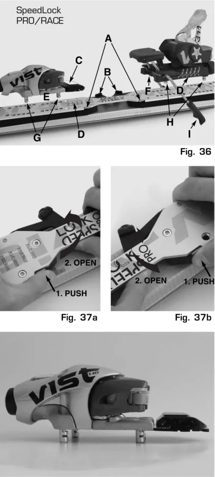
5.2.1 Plates/bindings components (Fig. 36):
A. Security device; B. Opening/closing lever;
C. Anti Friction Device (AFD) – sliding plate; D. Reference for the indication of the ski boot
length;
E. Toe piece base; F. Heel piece base; G. Toe piece coupling pin; H. Heel piece coupling pin; I. Ski brake rods.
5.2.2 Bindings mounting instructions 1.Opening of the blocking system
Toe piece: to mount the toe piece on the SPEEDLOCK™ PRO/RACE plate, first push the steel lever (Fig. 36-A) of the security system inside the plate and keep it pushed while turning with the other hand the opening/closing lever (Fig. 36-B)of the system outside-forward (Fig. 37a).
Heel piece: to mount the heel piece on the SPEEDLOCK™ PRO/RACE plate, first push the steel lever (Fig. 36-A) of the security system inside the plate, and keep it pushed while turning with the other hand the opening/closing lever (Fig. 36-B)of the system outside-back (Fig. 37b).
Once opened the levers, don’t force the system pushing them up-down.
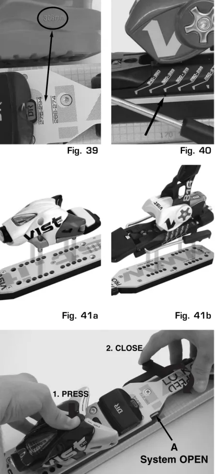
2.Toe/Heel piece placing
Make sure that no snow and/or ice, dirt or similar are placed between plate and bindings to allow the fixation of bindings.
Place the toe piece, with AFD set (Fig. 38), and the heel piece on the plate. To find the right position, refer, for the different boot lengths, to the indications printed on the upper part of the plate for the toe piece (Fig. 39), and on the lateral part of the heel piece base connected with the point “mounting position’’ for the heel piece (Fig. 40). The length of the boot is indicated in mm on the boot (Fig. 39). Introduce the coupling pins that stick out from the toe and heel piece in the holes of
the plate (Fig. 41a, 41b). 19
Fig. 36
Fig. 37b
Fig. 37a
Fig. 38
1. PUSH 2. OPENSpeedLock
PRO/RACE
A
B
C
D
D
E
F
G
H
1. PUSH 2. OPENI
Fig. 40
Fig. 39
Fig. 41b
Fig. 41a
Fig. 42a
3.Toe/Heel piece fixing
Once found the right position, push firmly the toe piece against the plate and set back the opening/closing lever turning it inside-back
(Fig. 42a) and blocking the security system
(Fig. 42b). Repeat the same operation to fix the heel piece. Push firmly the heel piece against the plate and set back the opening/ closing lever turning it inside-forward (Fig. 43a)
and blocking the security system (Fig. 43b).
Warning:the opening/close lever must be set in the plate before skiing to put the security system back into the appropriate seat (‘’blocking position’’) to avoid unintentional or accidental opening. Never force or tamper the levers for the opening/closing operations.
4. Manual and visual control
Shake manually and check visually in order to make sure that the binding is firmly fixed on the plate without any play (Fig. 44).
Check that the security system is blocked. In case of doubts, repeat the operation according to the description.
Warning:make sure that the security system is blocked or the performance and safety of your bindings will be seriously compromised.
5. Ski brake mounting
Mount the ski brake by introducing the metal tabs into the notches at the front of the heel piece base (Fig. 45). Then, screw only the central screw to fix the ski brake with the Pozidriv (PZ) n.3 screwdriver (Fig. 46).
6. Binding adjustment
For the binding adjustment, refer to the included instructions of the VIST bindings! Initial installation and adjustment of your bindings should be performed by your Authorized VIST Dealer. The adjustment and performance of your ski-boot-binding system should be checked by your Authorized VIST Dealer at least once each season.
7. Transferring bindings between skis
Once your VIST SPEEDLOCK™ bindings have been mounted and adjusted by your
Authorized VIST Dealer, you can take advantage of the VIST SPEEDLOCK™ system by moving your bindings from one pair of skis to another with the SPEEDLOCK™ PRO/RACE Plate. Simply follow the
instructions above, taking care to keep the same positions for your coupling pins. As with any bindings, however, use of boots other than those with which the system was
1. PRESS
2. CLOSE
A
21 originally set up requires testing and
verification by your ski shop.
Warning:Your ski-boot-binding system is designed to release the boot from the ski when certain forces on the system reach preset values, but the binding WILL NOT RELEASE OR RETAIN at all times where release or retention may prevent injury, and that it CANNOT prevent all injuries to any part of the user’s body. Lower release/retention settings increase the
binding’s ability to release, but also increase the risk of injury due to inadvertent release, and higher release/retention settings will increase retention but also increase the risk of injury due to non-release. Injuries caused by unwanted release or retention, and from falls, snow, terrain and weather conditions, collisions with people, man-made and natural obstacles, and from other causes are inherent risks of the sport which are assumed by all participants and spectators.
Fig. 43b
Fig. 42b
Fig. 46
Fig. 45
Fig. 44
CONTROL!
SYSTEM BLOCKEDFig. 43a
2. CLOSE 1. PRESS SYSTEM BLOCKEDA
System OPEN
Tab. 1
23
6.0 Defining and adjusting the
release settings
The release settings for VIST bindings defined with the following procedure are in conformity with international standards such as ISO 8061 and 11088 and ASTM F939. These standards were developed based on the needs reported by industry representatives of the sector, groups of actual users, experts and researchers. These standards are considered to supply the best binding adjustment solution, enabling safe release in case of accidents, and to provide maximum retention in normal skiing conditions. If you follow this procedure you will lower to the minimum any risk of accidents due to wrong adjustments of DIN settings. However, skiing entails many risks that cannot be directly correlated to the retention and release features of the binding, and even bindings that are adjusted precisely may not release in every load situation or guarantee retention all types of manoeuvres.
USING THE CHART
The following information concerning the skier must be known in order to determine the most appropriate adjustment settings: weight, height, type of skier, age, length of the sole of the boot used.These values are used in the table (tab. 1) in the manner described as follows.
1. Find the skier’s weight in the first column on the left and the height in the column next to it. If the skier’s weight and height are not on the same line choose the Initial Skier Code (from A to O). In the case of a height and weight that are in 2 different rows select the skier code that is closer to the top of the chart.
Example: A skier weigthing 50 Kg, 168 cm in height, of Type I, 22 years of age, who uses a boot with a sole 295 mm long. The Skier Code of this person is I and the correct visual indicator setting / Z setting is 3.5.
Carry out the following instructions in order to define the Visual Indicator /(Z scale) adjustment settings, and then adjust the bindings.
2.Then measure length of the sole of the boot. In the column corresponding to the boot sole length chosen you can see the visual
indicator / Z setting for adjusting the binding on the line corresponding to the letter (Initial Skier Code) identified before.
3.This table is based on Skier type 1. For Skier type 2, identify the setting in the column one row below the initial skier code. For Skier type 3, the column two rows below the initial skier code.
Attention:It is the skier’s responsibility to find his/her positioning in the “Type of Skier” chart. The information in the chart must only be used to help the skier to determine his/her correct position and to make him/her aware of the possible correlated risks concerning a wrong choice.
4.For skiers over 50 years of age, identify the setting in the column one row up.
5.In this way you identify the final visual indicator settings / Z settings, and in the column to the right the twisting moment that releases the binding.
Example:A skier weigthing 75 Kg, 175 cm in height, of Type II, 55 years of age, who uses a boot with a sole 305 mm long. The Skier Code of this person is K and the correct visual indicator setting / Z setting is 5.5.
It is the responsibility of the skier to determine their own skier type, with out influence from the technician. Skier type is different from skier ability and must not be confused. The skier type must be indicated on repair or rental form.
Skier’s classification based on ISO 11088 standards.
Skier type 1:
- Skis slowly and chooses gentle terrain or average slopes.
- Skis at slower speeds without taking risks. - Chooses lower than average binding release
settings. This may increase the risk of inadvertent binding release in order to
increase the binding’s ability to release in a fall. - Type 1 settings are applicable to entry level
skiers, or skiers that are uncertain of their classification.
6.1
Identifying the adjustment setting
with the VIST Adjustment Chart
Skier type 2:
- Skiers with average capability at a variety of speeds.
- Prefers variable terrain situations. - Also chooses difficult terrain but skis at
average speed.
- Chooses standard binding release settings. - Type 2 skiers are those who do not meet the
criteria of a type 1 or type 3 skier.
Skier type 3:
- Skiers with high technical-athletic capability. - Skis aggressively and at higher speeds. - Prefers average to steeper terrain.
- Chooses release settings that are higher than the standard setting. This may reduce the bindings ability to release in a fall in order to increase the bindings retention and to avoid inadvertent binding release.
Note: bindings adjusted on settings that are higher than Z-10 (red zone) are not in
conformity. Skiers use the bindings at their own risk in the case of settings that are higher than Z-10.
Toe-piece
Turn the screw (Figure 1, A for X-Key) on the front part of the toe-piece until the visual indicator / Z setting (Figure 1, B for X-Key) reaches the setting required (Fig. 47). Heel-piece
Turn the screw (Figure 2, D for X-Key) just under the lever rod of the heel-piece until the visual indicator/ Z setting (Figure 2, F) reaches the setting required (Fig. 48).
Fig. 47
Fig. 48
25
7.0 Checking procedure:
possi-ble propossi-blems and solutions
After having mounted and adjusted the bindings carry out the tests according to the procedures listed below. All the bindings that have already been used must be cleaned and dried before being checked. Never lubricate the anti-friction plate.
7.1
Testing the lateral elasticity
(return to center) of toe-piece
Fit the ski in the vice and check the elasticity of the binding with the boot fitted on. Hit the boot on both sides of the forefoot area with a rubber hammer.
Use the strength required to put the boot off center. After this operation the boot should return to its original position with a difference that must not be over 2mm.
If the test fails, check:
• If return to original position is incomplete or too slow:
- Check the heel-piece pressure: it could be excessive.
- In the case of a Demotype binding, check the size adjustment, it could be adjusted to a size that is too small (never tamper with elastic recovery screw for any reason whatsoever). - Check that boot is centred on the heel-piece. - Check that the boot is in conformity with the
required standards and that it is not excessively scratched.
- Check that the anti-friction plate is in good condition.
- If necessary, clean the sole of the boot and the anti-friction plate.
• If there is some space between the clamp of the toe-piece and boot (the boot is not fixed well):
- Check the heel-piece pressure: it could be insufficient.
- In the case of a Demotype binding, check the size adjustment, it could be adjusted to a size that is too large (never tamper with elastic recovery screw for any reason whatsoever). - Check that there is no lubricant or grease on
the boot or on the clamp.
• Check that no mounting screws are missing or broken (also check the screws under the toe-piece that are not visible after the mounting.
Simultaneously push the heel-piece lever downwards and the boot forwards (pressing down on the cuff of the boot). The heel of the boot should slightly lift up (approx. 5 mm). Simultaneously let go of the boot and the heel-piece lever. The boot should return quickly to the ski and the lever should return to its original position. Moreover, check if the brake fully closes.
If the test fails, check:
• If the heel-piece does not close or is difficult to close:
- Check if there is dirt or snow under the heel of the boot.
- Check length adjustment (size) and heel-piece pressure.
- In the case of a Demotype binding, check the size adjustment, it could be adjusted to a wrong size (never act on the elastic recovery screw for any reason whatsoever).
- Check that there are no signs of excessive wear on the heel.
- Check that the boot is fixed correctly in the binding.
• Check that no mounting screws are missing or broken.
These tests must be carried out only by specialized personnel always using machines specifically dedicated for the adjustment of ski bindings and provided with the required certifications. We recommend carrying out the adjustments according to the instructions for use of every individual machine.
For several reasons the settings identified with the control instruments may be different to the registered visual indicator/ Z setting. There are many reasons for this:
- The boots are worn out on one side only or the sole is distorted, thus provoking friction differences.
7.2
Testing the vertical elasticity of
heel-piece
7.3
Mechanical testing of registered
release settings
- There are technical tolerances inside the springs of the bindings.
- There are differences due to mechanical friction in the bindings, due to dirt or improper lubrication.
In any case, VIST bindings are adjusted after production, and for this reason when they are new the differences are minimal. Therefore, the registered settings generally correspond to the effective twisting moment that releases the binding.
The maximum tolerances allowed by ISO standards are +/- 10% (but in fact these lower when the visual indicator / Z setting of the binding lowers).
7.3.1 If the tolerances of the release settings of the bindings are over +/- 10% proceed as follows:
• Check the ski boots:
- See chapter 2.3 at "Guidelines for checking the boots" section
• Check the bindings:
- Clean the bindings and if necessary, lubricate with grease for bindings.
- Repeat the release operation several times and check if it improves.
- Check the sliding plate of the toe-piece. The plates must not be damaged or scratched because this could compromise lateral release. Replace any damaged or missing plates.
• Turn the forward pressure adjustment screws and change the pre-set visual indicator / Z setting:
You can obtain an improvement by changing the visual indicator / Z setting of the indicator, and still remain within a range of +2 o –2 marks on the graduated scale.
7.3.2 If it is still not possible to go within the +/- 10% maximum tolerance allowed, proceed as follows:
If the cause is identified, replace the components causing the problem, and then repeat the complete check. Should the cause not be identifiable, contact the VIST North America Customer Service
(number: 866.900.8478 or e-mail: [email protected])
Attention:In these cases, for safety reasons do not consign the equipment to the customer unless he expressly requests it in writing and signs the request.
Attention:Modern testing instruments print out a test report in two copies. One copy is kept by the dealer (who must keep it for a period of five years, depending on the period prescribed by the law). The other copy must be consigned to the customer together with the equipment, as it confirms that the bindings were adjusted correctly. If the product is new, consign the test report, and repair form together with the guarantee. If the equipment has already been used, consign it together with the repair form.
Rental Visual and Mechanical Inspections The Mechanical inspections discussed in this section are required of US dealers and strongly recommended for dealers in Canada, both in the interest of consumer protection and as a part of a sound risk management program. Complete maintenance records must for all of the bindings and boots in a shops inventory for both pre-season and in-season inspections. Only pass / fail results should be recorded in the testing log. If bindings are switched from one pair skis to another, this should be noted in the records. To conform to the indemnification policies of VIST North America these record must be kept on file for a minimum of Five years or what ever is required by the statute of limitations in the state of your residence.
The purpose of the pre-season binding
inspections is to ensure that all components of the binding are functioning properly. Start by pre-selecting several random samples from your rental boot inventory. These samples must be clean and in good condition with out excessive sole wear. Select the sample boot sole lengths according to the pre-season inspection table below.
*example
Inspection range In use range
27
8.0 Rental and Demo Testing
8.1.1
Make all appropriate binding–to–boot adjustments and verify their accuracy. It is recommended that each binding component is set according to Pre-Season Inspection Table.
8.1.2
With bindings that have been used should be cleaned and lubricated before performing the following inspections and tests:
• Test the toe for lateral elastic travel and return to center.
• Test the heel for vertical elastic travel and return.
• Verification that release values are within the specified range.
Note: Any binding component that tests outside the “Inspection Range” should be inspected and re-tested. If the new testing results are still outside the “Inspection Range” but are within the “In-Use Range” a *correction factor must be applied to bring the mechanical test results within the “Inspection Range”.
8.1.3
For any component that tests outside of the “In-Use Range refer to the Troubleshooting section.
* A correction factor is determined by adjusting the binding component’s visual indicator scale at half-setting intervals until the binding component’s test results are within the “Inspection Range”. This correction factor expressed in a +/- value on the ski next to the affected binding
component toe/heel and recording in the ski/binding maintenance records.
The purpose of the In-Season inspection is perform inspections on random samples of rental and demo inventory during the season to ensure that the equipment is functioning properly. The sampling program must give every unit of inventory an equal chance of being selected in order to be considered as a valid test. The purpose of this random sampling test
8.1
Pre-Season Binding Inspections
8.2
In-Season inspections
Pre-Season Inspection Table
Sample Boot Sole Length 271 - 290 mm 6 37 43 50 58 63 145 165 194 229 243 Visual Indicator Twist Value Toe Forward Lean
is to detect, correct and prevent deficiencies. These deficiencies fall into the following categories:
8.2.1 Class 1 Deviations
These are deviations in torque test result that are outside the “Inspection Range” but are within the “In-Use Range”. These are minor deviations that require no corrective action unless these deviations exceed an acceptable number of the sample tested. Please refer to the “Sample Size” chart for the acceptable limits of class 1 deviations for a given sample size. Minor deviations in excess of the acceptable limits will cause the sample to fail and as a result of this the entire appropriate inventory must be inspected. Class 1 torque deviations should be corrected using a correction factor as explained in the previous section 1.1. Other additional class one deviations such as:
• Failed test for elastic travel • Improper ski brake operation • Poor boot to binding contact • Incorrect forward pressure
should all be corrected as they are discovered. These deviations do not warrant an inspection of the entire inventory unless these deviations exceed the acceptable # for a specific sample size, thus causing the sample to fail. By quickly identifying Class 1 Deviations this random sampling method can prevent more serious defects from occurring.
8.2.2 Class 2 Deviations
Class 2 Deviations are minor deviations that prompt inspection the entire inventory and require corrective action. Class 2 deviations are torque testing results that fall outside the “In-Use range but not more than 3 horizontal rows up or down from reference torque value. Whenever a Class 2 deviation is detected the source of the defect must be identified and all of the affective inventory must be inspected for the defect. The defect must be corrected according to the troubleshooting procedures or the affected component(s) must be removed from the inventory. Detection of a class 2 defect will cause the sample to fail.
8.2.3 Class 3 Deviations
Class 3 Deviations are major defects that prompt immediate corrective action and a review of all procedures. Class 3 deviations are torque test results that are greater than 3 horizontal rows above or below the reference torque value. In-season testing, sampling, and inspection usually make the occurance of a Class 3 Deviation unlikely. If a Class 3 Deviation is detected all defected components must be corrected or removed from service. Detection of a Class 3 Defective will cause the sample to fail.
8.2.4 Sample and Testing Frequency
The random sampling is conducted throughout entire season, the frequency is as follows: • The first sample test is conducted after the
first 7 days of operation.
• If the sample test passes then the next sample test is conducted after the next 7 days of operation.
• If the two consecutive samples pass, then the sample testing is conducted every 14 days. • If a sample fails at any time, daily sample
testing shall be conducted until two consecutive sample tests pass.
• Then sample testing will continue normally i.e., after 7, after 14 days stc.
Sample Sizes
Inventory Size (Pairs) 100 200 300 400 500 600 700 800 900 1000 2000 16 20 30 40 50 60 70 80 80 80 80 3 4 6 8 10 12 14 16 16 16 16 Sample Size (Units) Maximum Class 1 Deviations (Units)29
9.0 Warranty and limitation of
liability
Attention:the instructions attached to the bindings must always be consigned to the customer.
Should the product have sustained technical modifications, or should the mounting, service and repair procedures contained in this manual not have been properly carried out, the
manufacturer reserves the right to offer no form of guarantee whatsoever.
The VIST guarantee covers the initial purchaser against faulty materials, construction and functioning, for a period prescribed by law starting from the purchase date (for this reason the purchaser must keep the purchase receipt).
For any complaints, contact only VIST authorised dealers.
The guarantee is applicable only if the binding is mounted and adjusted by qualified personnel and only if it has not been subjected to improper use. VIST reserves the right to decide if a product should be repaired or be replaced with a product of the same value or if the purchaser must be reimbursed.
Limit of responsibility:
The guarantee does not cover damages that derive from improper use, wrong mounting or non compliance with the instructions for mounting and use, wrong adjustments, inappropriate maintenance, accidents, or incorrect use or normal wear. The guarantee does not cover normal wear of components subject to abrasion such as sliding plates, screen graphics, and glued components. VIST shall not be responsible for any type of indirect damages or for third party.
The VIST 2006-2007 Release Adjustment Chart is the only chart recommended for use with VIST bindings.If the skier expresses special concerns or reports a release or retention problem with the recommended settings, re-inspect the equipment to make sure all components function correctly and are calibrated appropriately. If equipment factors have been ruled out but the problem persists, the skier should reevaluate their skier type classification. Provide these skiers with the information stated in section 5.4 entitled
8.2.5 Sample criteria
An equal number of units (single ski/binding) must come from units that are classified as ready to rent, and are units that are classified as returned in “returned condition”
• Ready to rent units may be tested at any visual indicator setting and boot.
• Returned condition units must be tested as returned with the visual indicator setting and boot that they were retuned with.
8.2.6 Sample size
Sample size is defined as 5% of the inventory or not less that 16 units ore more than 80 units.
8.2.7 Procedures and Recording
Samples are inspected according to procedures used for pre-season binding inspections;
however the twist test only needs to be done in one direction (clockwise or counterclockwise). Pass/Fail records of all inspections should be recorded for the individual Ski/Binding.
9.1
Dealing with Skiers with release
or Retention Concerns
After the toe and heel piece have been set to the correct visual indicator setting using the procedures described above, perform the following tests. All used bindings should be cleaned with a damp cloth and lukewarm water before performing any inspections. Do not lubricate the AFD or toe and heel cups.
Function Test –Toe (Lateral Elasticity)
With the ski held securely, hit the boot near the toe with your hand or a rubber mallet hard enough to displace the toe of the boot slightly but not far enough to trigger a release. If you have triggered a release, start over. The boot should snap back to within 2 millimeters of its original position after being hit from either side. If the system passes, mark "Pass" in the correct boxes on the Workshop Form and proceed to function test the heel.
If the system fails, perform the following trouble shooting procedure:
• For a slow or incomplete return to center:
1.Check the forward pressure – it may be too high.
2.Check that boot is centered in the heel cup.
3.Check for non-standard boot, or excessive wear.
4.Check that the AFD is in good condition.
5.Check for dirty boot sole or AFD and clean as necessary.
• If the boot slides in toe cup:
1.Check the forward pressure – it may be too low.
2.Check for lubricant on boot or toe cups. • Check for missing, stripped or loose mounting screws, including the screw under the toepiece which cannot be seen after final assembly.
Function Test-Heel (Vertical Elasticity) Depress the heel lever of the binding while pulling forward lightly on the upper cuff of the boot. The heel of the boot should move slightly upward (about 5mm) through the vertical retention range of the heel. Release both hands simultaneously. The boot should return quickly to the ski, and the heel lever should return quickly to its fullest upright position.
If the system passes, mark "Pass" in the correct boxes on the Workshop Form and proceed to the Verification of Release Values.
Information For Skiers Requesting Discretionary Settings.
Skiers who have experienced retention problems may choose to increase their Skier Type classification and accept a narrower margin of release in order to gain a wider margin of retention.
Skiers who feel the binding should release more often when they fall may choose to decrease their classification and accept a narrower margin of retention in order to gain a wider margin of release.
If the release/retention problem is only evident in one binding component (toe or heel) only that component may need to be reclassified.
To document the skier’s classification selections, separate the skier’s twist (toe piece)
classification from their forward lean (heel piece) selection with a slash (Toe/Heel).
Example: [ I/II ] means that Type I has been selected for the toe piece and Type II for the heel. Use this same method to record Skier Code and Initial Indicator Value.
Example: [G/H] means that Skier Code G has been used for the toe piece and Skier Code H for the heel piece. [5/6] means that Initial Indicator Value 5 has been used for the toe piece and Initial Indicator Value 6 has been used for the heel piece.
If a skier selects discretionary settings lower than those derived from Skier Type I, record this selection with a (-) symbol to the left of Type I on the workshop form (-1 Setting).
If a skier selects discretionary settings higher than those derived from Skier Type III, record this selection with a (+)symbol to the right of Type III on the workshop form (+3 Setting). Skiers who request these settings outside those resulting from Skier Types I, II and III should be warned that their decision may increase risks of injury due to non-release or inadvertent release. Always note clearly on the workshop ticket that the setting was made at the skier’s specific request and that the skier was given these warnings. Some skiers may insist upon settings outside of the -I or III+ range. These choices, and the skiers’ stated reasons for making these choices, must also be clearly noted on the workshop ticket. Be sure to obtain an additional signed and dated warning and release like that in section 11.2, which must be attached to the completed workshop ticket.
9.2