Comparison of LFC Optimization on Micro-hydro
using PID, CES, and SMES based Firefly
Algorithm
KadaryonoDepartment of Mechanical Engineering University of Darul Ulum
Jombang, Indonesia ani
[email protected]
Askan
Department of Mechanical Engineering University of Darul Ulum
Jombang, Indonesia [email protected]
Rukslin
Department of Electrical Engineering University of Darul Ulum
Jombang, Indonesia [email protected] Asnun Parwanti Department of Civil Engineering
University of Darul Ulum Jombang, Indonesia [email protected]
Machrus Ali
Department of Electrical Engineering University of Darul Ulum
Jombang, Indonesia [email protected]
Iwan Cahyono Department of Civil Engineering
University of Darul Ulum Jombang, Indonesia [email protected] Abstract—Micro-hydro gets potential energy from water
flow that has a certain height difference. Potential energy is strongly influenced by high water fall. Potential energy through pipes, incoming turbines converted into kinetic energy. The kinetic energy of the turbine coupled with the generator is converted into electrical energy. Some components used for micro-hydro power generation, among others; intake, settling basin, headrace, penstock, turbine, draft tube, generator, and control panel. Water flows through the pipe into the turbine house so it can rotate the turbine blades. Turbine rotation is used to rotate a generator at the micro hydro generator. The most common problem with micro-hydro generating systems is inconsistent generator rotation caused by changes in connected loads. Load changes can cause system frequency fluctuations and may cause damage to electrical equipment. Artificial Intelligence (AI) is used to obtain the right constants to obtain the best optimization. In this study compare the control method, namely; Proportional Integral Derivatives (PID), Capacitive Energy Storage (CES), and Superconducting Magnetic Energy Storage (SMES). This study also compared the method of artificial intelligence between Particle Swarm Optimization (PSO) method has been studied with the method of Firefly Algorithm (FA). Overall this study compares 11 methods, namely methods; uncontrolled, PID-PSO method, PID-FA method, CES-PID-PSO method, CES-FA method, SMES-PSO method, SMES-FA method, PID-CES-PSO method, PID-CES-FA method, PID-SMES - PID-CES-PSO, and PID-SMES-FA method. The results of the simulation showed that from the 11 methods studied, it was found that the PID-CES-FA method has the smallest undershot value, ie -7.774e-03 pu, the smallest overshoot value, which is 4.482e-05 pu, and the fastest completion time is 7.11 s. These results indicate that the smallest frequency fluctuations are found in the PID-CES-FA controller. Thus it is stated that the PID-CES-FA method is the best method used in the previous method. This research will use other methods to get the best controller.
Keywords—CES, Firefly Algorithm, micro-hydro, PID, SMES.
I. INTRODUCTION
In micro-hydro operation, stability issues are of major concern. In order for the frequency to be always stable, the rotational speed of the generator must be fixed. The rotational speed of the generator can be affected by the size or the amount of the load. The addition of a very large load will reduce the rotating density, otherwise a large load reduction will accelerate the generator spin. So that the
frequency will increase and if passing the standard will harm the consumer electrical equipment.
Therefore, to support this micro-hydro performance, setting or controlling the load frequency is required, to always be in the work area. Micro-hydro control is done automatically by governing the governor. Servo motor as governor set the opening height, so that the incoming water flow can be adjusted with the load. So the system can adjust the load power and can reduce the frequency change[1].
Load Frequency Control (LFC) is designed using a controller; Proportional Integral Derivatives (PID), Capacitive Energy Storage (CES) [2], and Superconducting Magnetic Energy Storage (SMES)[3]. All three controllers are tuned using artificial intelligence, namely the method of Particle Swarm Optimization (PSO) and Firefly Algorithm (FA). Because, Artificial Intelligent (AI) is often used to develop various disciplines such as vehicle steering controllers [4][5], as micro-hydro control [6], and others. In this study used the method Firefly Algorithm (FA) [7]. The FA method is used as tuning PID, CES, and SMES controller. With this comparison obtained the best control method. The best results will be applied at micro-hydro plants in Jombang, East Java, Indonesia. This research involves scientists from various disciplines, namely; mechanical engineering, electrical engineering, and civil engineering.
II. SYSTEM MODELING A. Micro-hydro Power Plant
The micro-hydro power plant on harnessing potential energy from the height difference and the amount of water discharge. The ponsial energy from the water passes through the pipe and rotates the turbine shaft to generate mechanical energy. This mechanical energy drives the generator and generates electrical energy. Micro hydro power plants must have a water source that always flows throughout the year. The electric power generated by the power generator (Pth) depends on the value of the water discharge (Q) and the waterfall height (H). The equation can be formulated as follows::
3
[ ] [ / ]. [ ]. [ / ]
th
P W =Q m s H m k N kg (1)
The efficiency (ηgen) of the turbine and generator is
of 0.8 causing the actual electrical value to be lower than the
generator power (Pth).
3
[ ] [ / ]. [ ]. [ / ]. .
real turbin gen
P W =Q m s H m k N kg η η (2)
For pumps used as turbines, the efficiency values varied from 0.6 to 0.8, in this study used 0.8. For cross-flow turbines, values varying from 0.5 to 0.7, in this study are used 0.6. While the generator used in the micro-hydro power plant system here is using an induction generator, a servo motor operated as a governor, and some components are modeled on the simulation using the Matlab-Simulink program. The following figure shows the configuration of the designed micro-hydro power plant.
Fig. 1. Block diagram of Micro-hydro System[6] The signal change (Δω) will be forwarded to the servo motor block functioned as governor. The parameters required for signal strengthening are Ks and Ts. The output of the governor is passed to the limiter to limit the signal. Limiter is used to limit the highest and lowest saturation values in order not to exceed the specified value. The limiter output goes to the turbine block. The micro-hydro parameters used in this study can be shown in Table 1..
Table 1. Micro Hydro Parameter [6]
Parameter Value Item Tb 1 Water turbine time response (s)
Kg 1 Reinforcement of inductor generator regulator (s) Tg 13,333 Response time on generator induction (s) K1 5 Error Detection confirmation constant K2 8,52 Frequency of frequency deviation constant K3 0.004 Strengthening Error Detection
T 0,02 Time response Error Detection Ts 0,1 The governor's time constant (s) Ks 2,5 Strengthening governor Sg 40 Micro-hydro power generator rating (kVA)
pf 0,8 Power Factor
Vg 400/231 Nominal voltage generator (V)
ω 1500 Nominal rotational speed (rpm) fg 50 The nominal frequency of micro hydro (Hz)
B. Capacitive Energy Storage (CES)[2]
Capacitive Energy Storage (CES) is a device used to store and release large amounts of electrical power quickly. CES consists of Storage Capacitors (SC) and Power Conversion Systems (PCS). The energy stored by the CES on the capacitor in the form of an electric field, can be shown in Figure 2.
Fig. 2. Capacitive Energy Storage
Storage capacitors consist of discrete capacitors arranged in parallel. Storage capacitors are connected via a 12-pulse Power Conversion System (PCS) to Mesh. The leakage and dielectric energy losses of the bank capacitor at CES are modeled by resistors R in parallel with the capacitor (C). PCS converts to DC and from DC to AC Inverter. Bypass Thyristor serves to provide the current path (Id) when the converter fails. The DC breaker diverts the current (Id) to the resistor point (Rd) if the converter fails. The bridge voltage (Ed) is shown in equations 3 and 4.
D d d d E I R E =2 0cosα−2 (3) 2 2 1/2 max min 0 [ ] 2 d d d E E E = + (4)
If the system is interrupted, the capacitor voltage becomes too low and the voltage will return to its normal value quickly. The energy will be absorbed by the capacitor and can cause the control to be disconnected. To solve this problem, the lower limit for the capacitor voltage, taken 30% of the rating value (Ed0). The lower limit of voltage can be seen in equation 5.
min 30 0
d d
E = E (5)
The CES voltage will return to its initial value quickly. After the disturbance occurs, the CES unit must be ready to work for subsequent load changes. The voltage deviation of the capacitor is used as a feedback signal in the CES control loop. ∏ CES K DC sT + 1 1 VD K R sC 1 1 + d I Δ d I Δ +
−
+ + d d E E0+Δ d E Δ 0 d E f Δ CES P Δ Fig. 3. CES Block diagramHere's the voltage deviation of the capacitor ΔEd,
1 1 d d E I sC R Δ = Δ + (6)
CES output power released to the system during load changes is as follows, 0 ( ). CES d d d P E E I Δ = + Δ Δ (7)
C. Superconducting Magnetic Energy Storage (SMES) SMES stores energy in the magnetic field obtained from Direct Current (DC) into the cryogenic cooled superconducting coil. A SMES connected to a power system, consisting of a cryogenic cooling system, superconducting coil, and Power Conditioning System (PCS) with control and protection functions. PCS is commonly referred to as the power electronics center of the SMES coil. SMES schematic diagram can be seen in figure 4. [3]. Controller Coil Protection Cryogenic System VCoil ICoil Dewar Power Conversion System
CSI or VSI + dc-dc chopper Transformer Bypass Switch Coil AC Line
Fig. 4. SMES schematic diagram.
In principle, superconductors have near-zero losses at cold temperatures. The coolant used is Helium liquid which is able to cool to 4 K. PCS is used to transfer energy from the SMES coil to the system. A PCS uses a dc link capacitor to connect a voltage source from the SMES coil to the system. The working principle of SMES is divided into three, namely charging mode, standby mode and discharging mode. The SMES performance setting is performed by adjusting the duty cycle of the converter which in this case uses a Gate Turn Off (GTO) thyristor .
Fig 5. Configure SMES
To effectively control the power balance of the generator, SMES is placed on the bus terminal of the generator. From some SMES equations of reference, a block diagram of the SMES PID controller used is shown in Figure 6. w ( + + ) 1+ST I p D K S K SK S Δω 1+ C DC K ST 1 SM SL
π
Fig 6. Block diagram PID SMES
In this study, PID-SMES is installed on micro-hydro power system. The PID-SMES installation is on the induced generator bus terminal when there is a burden of changing the load. The SMES parameters can be seen in Table 3.
Table 3. SMES Parameters Parameters Tuning Value
Ksmes 90
Tdc 0.0176
tw 7.6616
Kp 8
Ki 6.8462
D. Firefly Algorithm (FA)[7]
The method used to optimize the PID parameter is the Firefly Algorithm (FA) method. The algorithm was first discovered by Dr. Xin-She Yang at Cambridge University in 2007. The algorithm diagram of the Firefly Algorithm (FA) method used in this research study can be seen in Figure 3. The objective function used to test the stability of the system is with Integral Time Absolute Error (ITAE)[8][7].
0
( ) t
ITAE=
tΔωt dt(11)
The PID parameters set by FA are Kd, Kp, Ki. The data of the standard FA parameters used are shown in Table 4:
Table 4. FA Parameters Parameters Value Alpha 0.25 Beta 0.2 Gamma 1 Dimensi 3 Number of Fireflies 50 Maximum iteration 50 Kp 0 – 50 Ki 0 – 10 Kd 0 – 10
E. Particle Swarm Optimization (PSO).
his algorithm is inspired by the behavior of swarm in search of food. Particle Swarm Optimization (PSO) is defined as a swarm swarm that can define trajectories by their own best performance and groups. In this paper, swarm partition optimization solves the problem of performance optimization Load frequency control in reducing frequency fluctuations through the description of the algorithm to find the value of the constants PID, CES and SMES.[10][11].
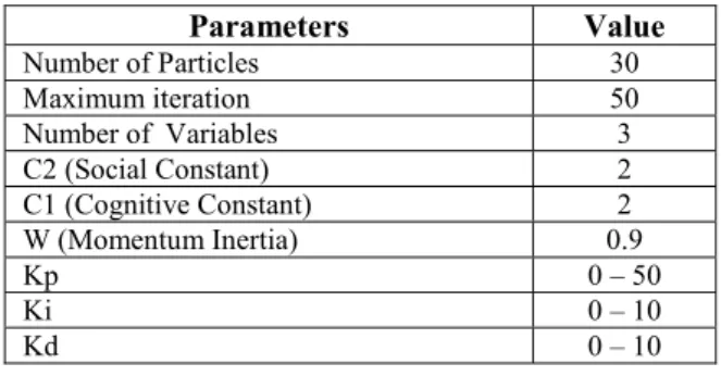
The data of PSO parameters can be seen in Table 5. TABLE 5.PSOPARAMETERS
Parameters Value Number of Particles 30 Maximum iteration 50 Number of Variables 3 C2 (Social Constant) 2 C1 (Cognitive Constant) 2 W (Momentum Inertia) 0.9 Kp 0 – 50 Ki 0 – 10 Kd 0 – 10
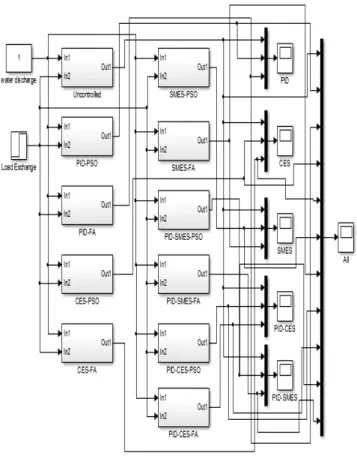
III. PRESULT OF SIMULATION AND ANALYSIS The design of some micro-hydro controllers can be seen in figure 7.
Fig.7. Micro-hydro controller design
Micro-hydro controller constants can be seen in Table 6, table 7, and Table 8;
TABLE 6.OPTIMIZATION RESULTS WITH PID
Parameter PSO FA
Kp 16.790915 79.627021
Ki 1.716562 7.161799
Kd 0.091662 6.024251
TABLE 7.PID OPTIMIZATION RESULTS WITH CES
Parameter PSO FA Kces 69.4785 82.1232 Tdc 0.01430 0.0643 Kp 11.7909 49.6827 Ki 1.7165 39.6212 Kd 0.09166 6.1234
TABLE 8.PID OPTIMIZATION RESULTS WITH SMES
Parameter PSO FA Ksmes 81.302 90.634 Tdc 0.02136 0.0176 Twi 7.0321 7.6162 Kp 7.0864 8.8642 Ki 2.6744 6.8463 Kd 0.0083 0.1932
By using the FA method obtained tuning PID controller with a large constant parameter Kp = 79.627021, Ki = 7.161799, and Kd = 6.024251. With CES method, there are big constants Kces = 82.1232, Tdc = 0.0643, Kp = 49.6827, Ki = 39.6212, and Kd = 6.1234. With the method of SMES obtained constant Ksmes = 90.634, Tdc = 0.0176, Twi = 7.6162, Kp = 8.8642, Ki = 6.8463, and Kd = 0.1932.
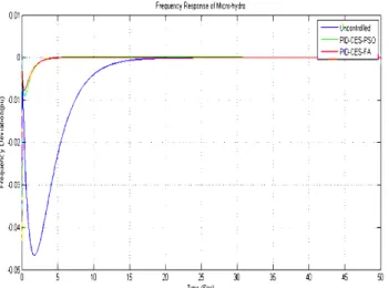
Figure 8-13 shows the micro-hydro frequency response for each control design.
Fig. 8. Micro Hydro Frequency with PID
Fig. 9. Micro Hydro Frequency with CES
Fig. 11. Micro Hydro Frequency with PID-CES
Fig. 12. Micro Hydro Frequency with PID-SMES
Fig. 13. Plot All Graphic of Control Model
The results of overshoot, undershoot and settling time can be seen in Table 9.
TABLE 9.OVERSHOOT RESULT OF EACH MODEL Controller Overshoot (pu) Undershoot (pu) Settling time (s)
Uncontrolled 0.0000 -4.661e-02 25.012 PID-PSO 3.945e-04 -2.242e-02 35.653
PID-FA 2.985e-03 -9.448e-03 15.653
CES-PSO 3.582e-03 -1.191e-02 9.883
CES-FA 4.111e-04 -9.375e-03 7.352
SMES-PSO 7.154e-03 -1.701e-02 21.342 SMES-FA 1.961e-03 -8.954e-03 19.763 PID-CES-PSO 1.798e-04 -9.063e-03 7.748 PID-CES-FA 4.482e-05 -7.774e-03 7.11
PID-SMES-PSO 7.000e-03 -1.011e-02 17.863
PID-SMES-FA 1.931e-03 -8.531e-03 11.361 From Figure 8-13 and Table 9 shows that the overshoot, undershot, and settling time of the method; uncontrolled (0.00, 4.661e02, 25.012), PIDPSO method (3.945e04, -2.242e-02, 35.653), PID-FA method (2.985e-03, -9.448e-03, 15.653), CES-PSO method (3.582e-03, -1.191e-02, 9.883), CES-FA method (4.111e-04, -9.375e-03, 7.352), SMES-PSO method (7.154e-03, -1.701e-02, 21.342), SMES-FA method (1.961e-03, -8.954e-03, 19.763), PID-CES-PSO method (1.798e-04, -9.063e-03, 7.748), PID-CES-FA method (4.482e-05, -7.774e-03, 7.11), PID-SMES – PSO (7.000e-03, -1.011e-02, 17.863), and PID-SMES-FA method (1.931e-03, -8.531e-03, 11.361). The simulation results show that the PID-CES-FA method has the smallest undershot value, ie -7.774e-03 pu, the smallest overshoot, ie 4.482e-05 pu, and the fastest settling time of 7.11 s. thus it is stated that the PID-CES-FA method is the best method used from the previous method..
IV. CONCLUSION
By using Firefly Algorithm (FA) as the method of tuning the Capacitive Energy Storage (CES) controller, the result of tuning of CES parameter for Kces 88,8888, Tdc is 0.0563, Kp is 63.6297 and Ki is 43.7886, and Kd is 9.6385. The simulation results show that the PID-CES-FA method has the smallest undershot value, ie -7.774e-03 pu, the smallest overshoot, ie 4.482e-05 pu, and the fastest settling time of 7.11 s. thus it is stated that the PID-CES-FA method is the best method used from the previous method.
V. REFERENCES
[1] D. Henderson, “An advanced electronic load governor for control of micro hydroelectric generation,” IEEE Trans. Energy Convers., vol. 13, no. 3, pp. 300–304, 1998. [2] I. T. Yuniahastuti, I. Anshori, and I. Robandi, “Load
frequency control (LFC) of micro-hydro power plant with capacitive energy storage (CES) using bat algorithm (BA),” in Proceedings - 2016 International Seminar on Application of Technology for Information and Communication, ISEMANTIC 2016, 2017, pp. 147–151. [3] M. R. I. Sheikh, S. M. Muyeen, R. Takahashi, T. Murata,
and J. Tamura, “Minimization of fluctuations of output power and terminal voltage of wind generator by using STATCOM/SMES,” in 2009 IEEE Bucharest PowerTech: Innovative Ideas Toward the Electrical Grid of the Future, 2009.
[4] M. Ali, F. Hunaini, I. Robandi, and N. Sutantra, “Optimization of active steering control on vehicle with steer by wire system using Imperialist Competitive Algorithm (ICA),” in 2015 3rd IEEE -International Conference on Information and Communication Technology, ICoICT 2015, 2015, pp. 500–503.
[5] H. Kusuma, M. Ali, and N. Sutantra, “The comparison of optimization for active steering control on vehicle using PID controller based on artificial intelligence techniques,” in Proceedings - 2016 IEEE- International Seminar on Application of Technology for Information and Communication, ISEMANTIC 2016, 2017.
[6] M. Muhlasin, R. Rukslin, A. Raikhani, and M. Ali, “The FA-ANFIS Hybrid Method is used for LFC Optimization in Micro Hydro Power Generation,” in Seminar Nasional Teknik Elektro (FORTEI 2017), 2017, pp. 225–229. [7] X. S. Yang, “Firefly algorithms for multimodal
optimization,” in Lecture Notes in Computer Science (including subseries Lecture Notes in Artificial Intelligence and Lecture Notes in Bioinformatics), 2009, vol. 5792 LNCS, pp. 169–178.
[8] M. Alb, P. Alotto, C. Magele, W. Renhart, K. Preis, and B. Trapp, “Firefly Algorithm for Finding Optimal Shapes of Electromagnetic Devices,” IEEE Trans. Magn., vol. 52, no. 3, pp. 1–4, 2016.
[9] X. S. Yang, “Firefly Algorithm,” Nature-Inspired Metaheuristic Algorithms, pp. 79–90, 2007.
[10] T. M. Blackwell, J. Branke, and X. Li, “Particle Swarms for Dynamic Optimization Problems,” Swarm Intell., vol. 52, no. 1, pp. 193–217, 2008.
[11] Z.-H. Zhan, J. Zhang, Y. Li, and H. S.-H. Chung, “Adaptive particle swarm optimization.,” IEEE Trans. Syst. Man. Cybern. B. Cybern., vol. 39, no. 6, pp. 1362– 1381, 2009.
![Table 1. Micro Hydro Parameter [6]](https://thumb-us.123doks.com/thumbv2/123dok_us/10949228.2983458/2.892.73.432.304.531/table-micro-hydro-parameter.webp)