Development of FPGA based Standalone
Tunable Fuzzy Logic Controllers
Bhaskara Rao Jammu
Department of Electronics and Communications Engineering
Development of FPGA based Standalone
Tunable Fuzzy Logic Controllers
Dissertation submitted in partial fulfillment of the requirements of the degree of
Doctor of Philosophy
in
Electronics and Communications Engineering
by
Bhaskara Rao Jammu
(Roll Number: 511EC103)
based on research carried out under the supervision of
Prof. Sarat Kumar Patra
and
Prof. Kamala Kanta Mahapatra
July, 2017
Department of Electronics and Communications Engineering
Department of Electronics and Communications Engineering
National Institute of Technology Rourkela
July 17, 2017
Certificate of Examination
Roll Number: 511EC103
Name: Bhaskara Rao Jammu
Title of Dissertation: Development of FPGA based Standalone Tunable Fuzzy Logic Controllers
We the below signed, after checking the dissertation mentioned above and the official record book (s) of the student, hereby state our approval of the dissertation submitted in partial fulfillment of the requirements of the degree of Doctor of Philosophy in Department of Electronics and Communications Engineering at National Institute of Technology Rourkela. We are satisfied with the volume, quality, correctness, and originality of the work.
Kamala Kanta Mahapatra Sarat Kumar Patra
Co-Supervisor Principal Supervisor
Bidyadhar Subudhi Debiprasad Priyabrata Acharya
Member, DSC Member, DSC
Dayal Ramakrushna Parhi Indra Narayan Kar
Member, DSC External Examiner
Sukadev Meher Kamala Kanta MahaPatra
Department of Electronics and Communications Engineering
National Institute of Technology Rourkela
Prof. Sarat Kumar Patra Professor
Prof. Kamala Kanta Mahapatra Professor
July 17, 2017
Supervisors’ Certificate
This is to certify that the work presented in the dissertation entitledDevelopment of FPGA
based Standalone Tunable Fuzzy Logic Controllerssubmitted byBhaskara Rao Jammu, Roll
Number 511EC103, is a record of original research carried out by him under our supervision and guidance in partial fulfillment of the requirements of the degree ofDoctor of Philosophy
in Department of Electronics and Communications Engineering. Neither this dissertation
nor any part of it has been submitted earlier for any degree or diploma to any institute or university in India or abroad.
Kamala Kanta Mahapatra Sarat Kumar Patra
Dedication
I dedicate my thesis to My Mother and My Child Taruni...Declaration of Originality
I, Bhaskara Rao Jammu, Roll Number 511EC103 hereby declare that this dissertation
entitledDevelopment of FPGA based Standalone Tunable Fuzzy Logic Controllerspresents my original work carried out as a doctoral student of NIT Rourkela and, to the best of my knowledge, contains no material previously published or written by another person, nor any material presented by me for the award of any degree or diploma of NIT Rourkela or any other institution. Any contribution made to this research by others, with whom I have worked at NIT Rourkela or elsewhere, is explicitly acknowledged in the dissertation. Works of other authors cited in this dissertation have been duly acknowledged under the sections “Reference” or “Bibliography”. I have also submitted my original research records to the scrutiny committee for evaluation of my dissertation.
I am fully aware that in case of any non-compliance detected in future, the Senate of NIT Rourkela may withdraw the degree awarded to me on the basis of the present dissertation.
July 17, 2017 NIT Rourkela
Acknowledgment
I owe sincere gratitude to the ones who have contributed greatly to completion of this thesis. First and foremost I would like to express my sincerest appreciation to my supervisor, Prof. Sarat Kumar Patra, who has guided me throughout my Ph.D. thesis with his patience and knowledge whilst allowing me to work in my own way. It was an honor for me to work with him during my time at NIT Rourkela. I would also like to acknowledge my co-supervisor, Prof. Kamala Kanta Mahapatra for his kind advice and inspiration.
“Agnyaana Timiraandhasya Gnyaana Anjana Shalaakayaa Chakshuhu Unmeelitam Yenam
Tasmai Sri Gurave Namaha”.
I would like to thank Board of Research for Fusion Science and Technology (BRFST) and Institute of Plasma Research, Gandhinagar for funding a major part of this research. The author would like to extend his gratitude towards Dr. Govindarajan, Mr.J. J. Patel, Mrs. Rachana Rajpal and Mr. Hitesh Patel of Institute of Plasma Research, Gandhinagar, for their contributions to this project.
I am thankful to all the faculty members of Electronics and Communication Engineering department for extending their valuable suggestions and help whenever I approached.
I would like to thank my friends Pallab, Bijay, Manas, Satyendra, Chitra, Varun, Mangal, Govind, Rama Krishna, Tom, Srinivas, Sujeevan and others who were with me in the ups and downs of my life during my Ph.D. work. I would like to extend gratitude to my seniors Prasant, Karuppanan, Venkat, Rajesh, Kanhu, Trilochan, Yogesh, Manab and Dipak.
I would also like to thank Prof. B. Subudhi, Prof. D. P. Acharya, Prof. D. R. Parhi and Prof. S. Meher for their innovative ideas and review during the entire duration of the project. I do acknowledge the academic resources that I have received from NIT Rourkela. I also thank the administrative and technical staff members of Electronics and Communication Engineering Department for their in time support.
In addition, I thank Dr. K V L Raju, Dr. R. Ramana Reddy and colleagues of MVGR College of Engineering for providing good workplace and encouragement. I also thank Dr.
M. V. S. Sairam, Dr. N. Bala Subramanyam, Dr. N. Balaji, the faculty of GVP College of Engineering and friends at JNTU Vizianagaram for their constant love and encouragement. I take this opportunity to express my regards and obligation to my father whose support and encouragement I can never forget in my life. I feel proud to acknowledge my father for his throughout support and motivation in my career for whom I am today and always. I would like to dedicate this thesis to my wife Nalini and my daughter Nikhila for their unconditional love, patience, and cooperation.
Finally, there is no word to describe my gratitude toward my other family members for their endless support and love during my life.
Jul 17, 2017 NIT Rourkela
Bhaskara Rao Jammu
Abstract
Soft computing techniques differ from conventional (hard) computing, in that unlike hard computing, it is tolerant of imprecision, uncertainty, partial truth, and approximation. In effect, the role model for soft computing is the human mind and its ability to address day-to-day problems. The principal constituents of Soft Computing (SC) are Fuzzy Logic (FL), Evolutionary Computation (EC), Machine Learning (ML) and Artificial Neural Networks (ANNs).
This thesis presents a generic hardware architecture for type-I and type-II standalone tunable Fuzzy Logic Controllers (FLCs) in Field Programmable Gate Array (FPGA). The designed FLC system can be remotely configured or tuned according to expert operated knowledge and deployed in different applications to replace traditional Proportional Integral Derivative (PID) controllers. This re-configurability is added as a feature to existing FLCs in literature. The FLC parameters which are needed for tuning purpose are mainly input range, output range, number of inputs, number of outputs, the parameters of the membership functions like slope and center points, and an If-Else rule base for the fuzzy inference process. Online tuning enables users to change these FLC parameters in real-time and eliminate repeated hardware programming whenever there is a need to change. Realization of these systems in real-time is difficult as the computational complexity increases exponentially with an increase in the number of inputs. Hence, the challenge lies in reducing the rule base significantly such that the inference time and the throughput time is perceivable for real-time applications.
To achieve these objectives, Modified Rule Active 2 Overlap Membership Function (MRA2-OMF), Modified Rule Active 3 Overlap Membership Function (MRA3-OMF), Modified Rule Active 4 Overlap Membership Function (MRA4-OMF), and Genetic Algorithm (GA) base rule optimization methods are proposed and implemented. These methods reduce the effective rules without compromising system accuracy and improve the cycle time in terms of Fuzzy Logic Inferences Per Second (FLIPS). In the proposed system
architecture, the FLC is segmented into three independent modules, fuzzifier, inference engine with rule base, and defuzzifier.
Fuzzy systems employ fuzzifier to convert the real world crisp input into the fuzzy output. In type 2 fuzzy systems there are two fuzzifications happen simultaneously from upper and lower membership functions (UMF and LMF) with subtractions and divisions. Non-restoring, very high radix, and newton raphson approximation are most widely used division algorithms in hardware implementations. However, these prevalent methods have a cost of more latency. In order to overcome this problem, a successive approximation division algorithm based type 2 fuzzifier is introduced. It has been observed that successive approximation based fuzzifier computation is faster than the other type 2 fuzzifier.
A hardware-software co-design is established on Virtex 5 LX110T FPGA board. The MATLAB Graphical User Interface (GUI) acquires the fuzzy (type 1 or type 2) parameters from users and a Universal Asynchronous Receiver/Transmitter (UART) is dedicated to data communication between the hardware and the fuzzy toolbox. This GUI is provided to initiate control, input, rule transfer, and then to observe the crisp output on the computer. A proposed method which can support canonical fuzzy IF-THEN rules, which includes special cases of the fuzzy rule base is included in Digital Fuzzy Logic Controller (DFLC) architecture. For this purpose, a mealy state machine is incorporated into the design. The proposed FLCs are implemented on Xilinx Virtex-5 LX110T. DFLC peripheral integration with Micro-Blaze (MB) processor through Processor Logic Bus (PLB) is established for Intellectual Property (IP) core validation. The performance of the proposed systems are compared to Fuzzy Toolbox of MATLAB. Analysis of these designs is carried out by using Hardware-In-Loop (HIL) test to control various plant models in MATLAB/Simulink environments.
Contents
Certificate of Examination ii
Supervisors’ Certificate iii
Dedication iv
Declaration of Originality v
Acknowledgment vi
Abstract viii
List of Figures xiv
List of Tables xviii
1 Background and Related Work 1
1.1 Fuzzy Logic Systems - An Overview . . . 2
1.1.1 Fuzzy Sets . . . 3
1.1.2 Fuzzy Set Operations . . . 5
1.2 Fuzzy Logic Controllers: Principles of Operation . . . 6
1.3 Hardware Implementations of Fuzzy Logic Controllers . . . 8
1.3.1 Analog Implementations of FLC . . . 8
1.3.1.1 Dedicated Integrated Circuit based Analog FLCs . . . 9
1.3.1.2 Programmable Integrated Circuit based Analog FLCs . . 10
1.3.2 Digital Implementations of FLC . . . 10
1.3.2.1 Dedicated Integrated Circuit based Digital FLCs . . . 12
1.3.2.2 Programmable Integrated Circuit based Digital FLCs . . 13
1.3.3 Generic Fuzzy Processors . . . 15
1.4 Standalone Tunable Digital FLCs . . . 18
1.5 Motivation of this Work . . . 19
1.6 Objective of this Work . . . 20
1.7 Problem Statement . . . 21
1.8 Outline of Thesis . . . 22
2 VLSI Architecture of Fuzzy Logic Controller with Rule Reduction 23 2.1 Introduction . . . 24
2.2 VLSI Architecture of FLC . . . 26
2.2.1 Fuzzifier . . . 27
2.2.2 Rule Base and Inference Engine . . . 28
2.2.3 Defuzzifier . . . 30
2.3 FPGA Utilization Analysis . . . 32
2.4 2-Overlap Membership Function (2-OMF) Rule Reduction . . . 33
2.4.1 2-OMF Method and its VLSI Architecture . . . 33
2.4.1.1 Rule Reduction using 2-OMF method . . . 33
2.4.1.2 VLSI Architecture . . . 35
2.4.1.3 Design Choices for Internal Modules . . . 36
2.5 Modified 2-Overlap Membership Function With Rule Active (MRA2-OMF) Rule Reduction . . . 40
2.6 Simulation Results and Performance Evaluation . . . 43
2.7 Summary . . . 45
3 Tunable Digital Fuzzy Logic Controller with rule reductions and Special Case Rule Base Support 48 3.1 Introduction . . . 49
3.2 Special Case Rule Base . . . 50
3.3 Modified 3-OMF Rule Active (MRA-3OMF) and Modified 4-OMF Rule Active (MRA-4OMF) Rule Reduction . . . 51
3.4 Configurable DFLC IP Core . . . 54
3.4.1 State Machine for Partial and Complete Rule Generation . . . 59
3.4.2 Interfacing DFLC IP Core . . . 60
3.4.2.1 MATLAB GUI and Operation . . . 62
3.4.2.2 DFLC IP Core Peripheral Connection to MicroBlaze Processor . . . 62
3.5 Simulation Results and Analysis . . . 65
3.6 System Implementation and Validation . . . 70
3.7 Plasma Position Control in Nuclear Fusion Reactor . . . 72
3.7.1 Aditya Tokamak System Modeling . . . 75
3.8 Control Strategy . . . 77
3.8.1 Using PID Control . . . 77
3.8.2 Plasma Position Control in Aditya using FLC and DFLC . . . 78
3.9 Summary . . . 80
4 Tunable Type 2 Fuzzy Logic Controller with Successive Approximation based Membership Function 82 4.1 Introduction . . . 83
4.2 Type 2 Fuzzy Logic Systems - An Overview . . . 84
4.2.1 Type 2 Fuzzy Sets . . . 84
4.2.2 Type 2 Fuzzy Set Operations . . . 85
4.2.3 Type 2 Fuzzy Logic Controllers . . . 86
4.3 Successive Approximation Type 2 Membership Function . . . 86
4.4 Tunable Type 2 Fuzzy Logic Controller . . . 90
4.4.1 Digital Architecture . . . 90
4.4.2 Tunable Parameters . . . 95
4.4.3 Inference Engine and Type Reducer . . . 96
4.5 Results and Discussion . . . 97
4.6 Summary . . . 101
5 FPGA Implementation of Genetic Algorithm (GA) based Rule Optimized Fuzzy Logic Controller 102 5.1 Introduction . . . 103
5.2 System Architecture . . . 105
5.3 Rule Base Extraction . . . 107
5.3.1 Rule Base Initialization . . . 108
5.3.2 A Genetic Algorithm for Tuning of the Rule Base . . . 109
5.3.2.1 Step1: Selection . . . 109
5.3.2.2 Step 2. Crossover . . . 109
5.3.2.3 Step3: Mutation . . . 111
5.3.2.4 Step4: Elitism . . . 113
5.4 Rule Base Transmission . . . 113
5.5 Hardware Architecture of the FLC . . . 115
5.6 Validation of Proposed FLC in Practical Systems . . . 118
5.6.1 Hang Data Function [2 input 1 output system] . . . 121
5.6.2 Chaotic Time Series [4 input 1 output system] . . . 122
5.6.3 Plasma Position Control in ADITYA TFTR . . . 124
5.6.4 Simulation and Hardware Implementation . . . 126
5.6.4.1 Simulation Parameters . . . 127
5.6.4.2 Hardware Implementation . . . 127
5.7 Summary . . . 128
6 Conclusion 130 6.1 Contributions of this thesis . . . 131
6.2 Limitations of this Work . . . 132
6.3 Future Research Directions . . . 133
List of Figures
1.1 Conventional sets to model the room temperature. . . 4
1.2 Fuzzy sets to model the room temperature. . . 4
1.3 The hardware structure of Triangular Membership Function . . . 7
1.4 The Structure of Fuzzy Logic Controller . . . 7
1.5 Classification of hardware implementations for fuzzy systems . . . 9
1.6 FPGA Design Flow . . . 17
2.1 The Architecture of FLC in RTL (Register Transfer Level) . . . 27
2.2 Calculation of membership values . . . 28
2.3 Pin Diagram of Fuzzifier . . . 28
2.4 Block Model of Mamdani Inference Engine . . . 30
2.5 Pin Diagram of 2 input 1 output Rule Evaluator . . . 31
2.6 Pin Diagram of 4 input 2 output Rule Evaluator . . . 31
2.7 Logic Utilization of FLC on different FPGAs . . . 32
2.8 2-OMF Rule reduction concept . . . 35
2.9 VLSI Architecture of 2-OMF Reduced Rule Base . . . 37
2.10 Finite State Machine . . . 37
2.11 Rule address before mapping . . . 38
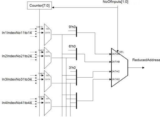
2.12 Circuit diagram of rule address generator for 2-OMF method . . . 39
2.13 Rule Address Mapping . . . 39
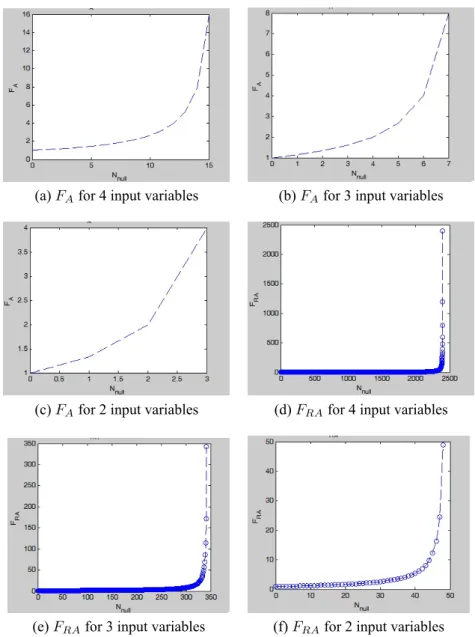
2.14 MRA2-OMF method fractional values with different input variables. . . . 41
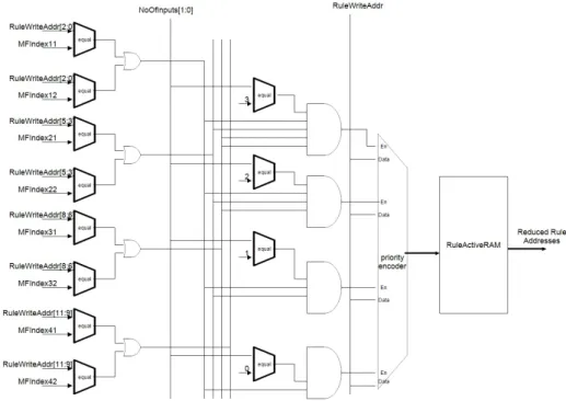
2.15 Circuit diagram of rule address generator for MRA2-OMF method . . . 42
2.16 Complete RuleBase Memory . . . 42
2.17 Dependency of 2-OMF Reduction on Rule Base Structure. . . 43
2.18 FLC operation on Virex5LX110T Board . . . 44
2.19 Comparative Analysis of Logic Utilization. . . 45
3.1 Less than 4 fuzzy membership functions overlapping at once . . . 52
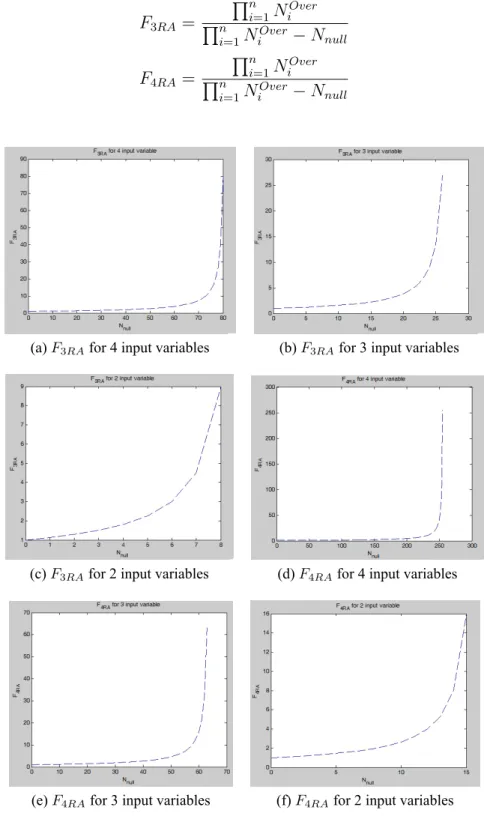
3.2 MRA3-OMF and MRA4-OMF fractional values with different input variables. . . 53
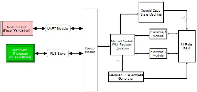
3.3 System Model for IP and Fuzzy Validation of Inference IP Core . . . 55
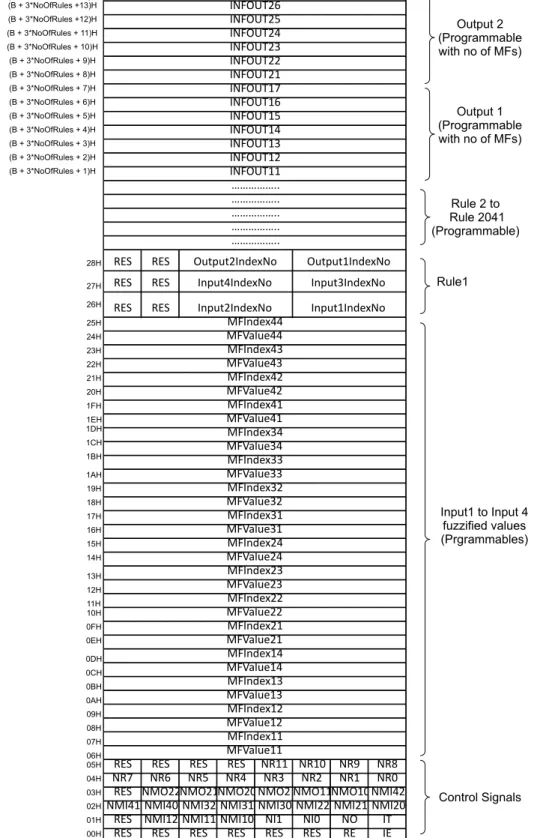
3.4 Memory Map to support different user configurations according to the system specification . . . 56
3.5 Rule reduction methods supported according to the present architecture . . 57
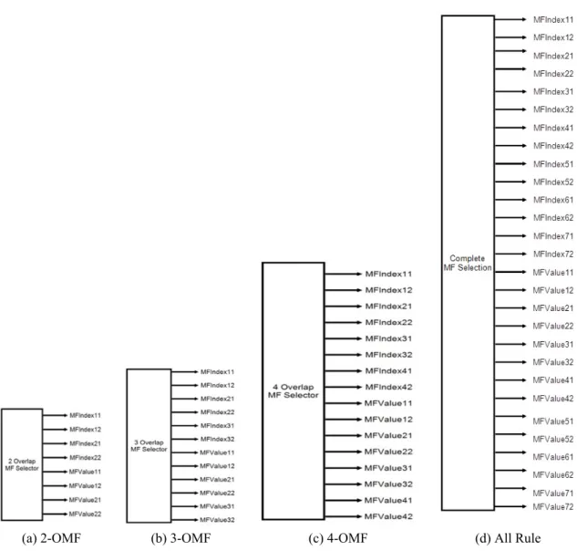
3.6 The rule-sector outputs for 2-OMFs, 3-OMFs and 4-OMFs rule reduction methods and all rules. . . 58
3.7 Finite State Machine to support special rule cases . . . 60
3.8 Detailed Design block diagram of DFLC . . . 63
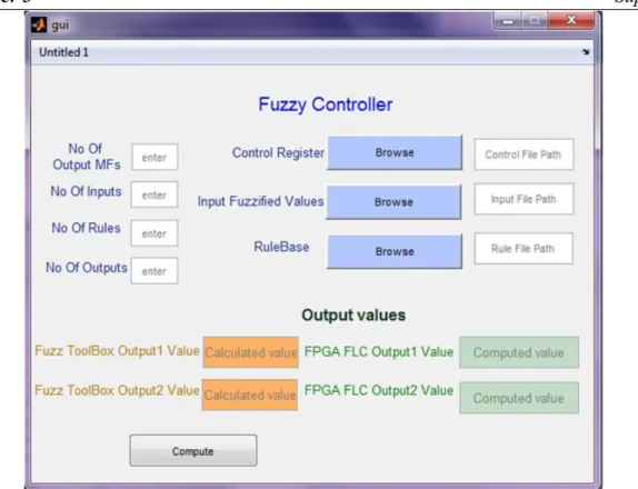
3.9 GUI to Initiate and Compare DFLC with Fuzzy tool box . . . 64
3.10 Configuration Register files of DFLC . . . 64
3.11 DFLC Peripheral Connection PLB Interface to Microblaze Processor . . . . 66
3.12 DFLC Peripheral to Microblaze Processor . . . 67
3.13 Test Model for partial rule support . . . 67
3.14 Simulation waveform of partial rule support . . . 68
3.15 Simulation waveform of single fuzzy statement . . . 68
3.16 Test Model for repeated rule . . . 68
3.17 Continuous Data Transfer from DFLC to MATLAB . . . 69
3.18 DFLC register updation from MB through PLB interface . . . 69
3.19 The setup for Hardware-in-loop Testing for DFLC . . . 71
3.20 Plant and Control output of 8 bit, 16 bit and MATLAB FLT test modes using HIL for two tank water level system . . . 72
3.21 Plant and Control output of 8 bit, 16 bit and MATLAB FLT test modes using HIL for ball and beam system . . . 73
3.22 Schematic of a tokamak . . . 74
3.23 Plasma Displacement inside Vacuum Chamber . . . 74
3.24 Control Strategy for Aditya TFTR . . . 77
3.25 Simulink model of radial plasma position control in Aditya TFTR with PID controller . . . 78
3.26 Simulink model of radial plasma position control in Aditya TFTR with FLC
and DFLC . . . 79
3.27 Performance of various controllers in presence of disturbances in plasma position . . . 81
4.1 Type 2 Fuzzy Set . . . 85
4.2 An Interval Type 2 Fuzzy Set . . . 87
4.3 Trapezoidal Type 1 and Type 2 Fuzzifiers . . . 88
4.4 Basic operation of Type 2 Fuzzification . . . 89
4.5 Basic function of membership circuit . . . 90
4.6 Algorithm flow of successive approximation . . . 91
4.7 Design of membership circuit module . . . 91
4.8 Circuit Model of Lower Membership Function . . . 92
4.9 Circuit Model of Upper Membership Function . . . 92
4.10 Type 2 Fuzzifer Block . . . 93
4.11 Top Level Architecture of Type 2 FLC . . . 93
4.12 Type 2 FLC Memory Map to support different user configurations . . . 94
4.13 MATLAB GUI to configure hardware Type 2 FLC . . . 97
4.14 Functional simulation result of Successive Approximation Division method 98 4.15 Functional simulation result of SAIT2FLC . . . 98
4.16 Simulink model of radial plasma position control in Aditya TFTR with FLC and SAIT2FLC . . . 99
4.17 Performance of various controllers in presence of disturbances in plasma position . . . 100
5.1 System Architecture of GA-FLC on FPGA . . . 106
5.2 Rule Base Design . . . 109
5.3 Flow diagram showing the GA based optimization of the fuzzy rule base . . 110
5.4 Shape of membership functions before and after crossover . . . 112
5.5 Reduced Rule Base with GA optimization . . . 113
5.6 Designed GUI for FLC using uses MATLAB for rule transmission to FPGA and computed value received from FPGA . . . 115
5.7 Block Diagram of Fuzzy Inference Module . . . 116
5.8 Calculation of membership values . . . 118 5.9 Process of fuzzy controller . . . 119 5.10 Defuzzification . . . 119 5.11 Block Diagrams of Fuzzy inference processing top module and fuzzifier,
inference and defuzzifier. . . 120 5.12 Hang function approximation with GA trained fuzzy system on FPGA . . . 122 5.13 GA-FLC versus ANFIS error plot . . . 123 5.14 Comparative plots between desired time series data, GA rulebase predicted
data, and GA-FLC on FPGA . . . 124 5.15 Radial Plasma Position Control of Aditya TFTR: HIL Simulation . . . 125 5.16 Performance of various controllers in presence of disturbances in plasma
position . . . 126 5.17 The functional simulation waveform obtained by ISim 14.2. . . 128 5.18 Crisp Data output from FPGA using UART captured on the Chipscope - Pro
List of Tables
1.1 T-norm duals in fuzzy literature . . . 5
1.2 Dedicated IC based analog FLCs . . . 11
1.3 Dedicated IC based digital FLCs - parallel rules . . . 14
1.4 Dedicated IC based digital FLCs - sequential rules . . . 14
1.5 Programmable IC based digital FLCs - FPGAs . . . 16
1.6 Major works on Generic FLCS . . . 18
2.1 Pin Description of Fuzzifier . . . 29
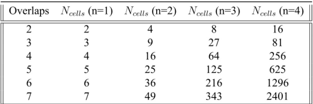
2.2 ComputedNcells with varyingnand Overlaps . . . 34
2.3 Implementation results for proposed methods . . . 45
2.4 Comparison proposed methods with other FPGA Implementations . . . 46
3.1 Rule search space for varying n and Overlaps . . . 54
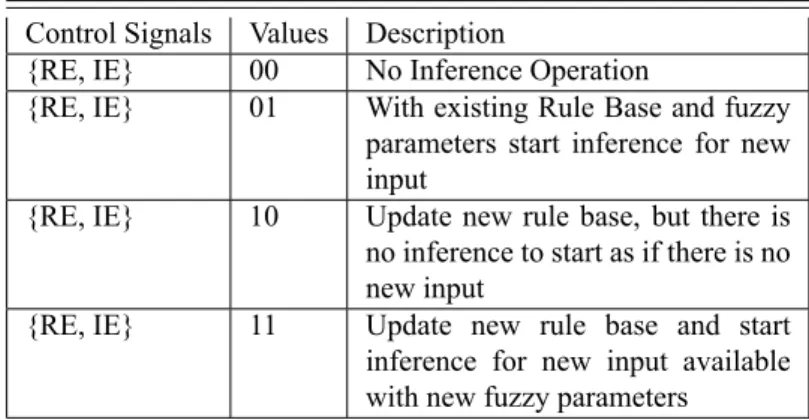
3.2 Control Signal Description to start different FLC programming options . . . 57
3.3 State Transition Table . . . 61
3.4 Hardware implementation: Comparison of all proposed methods . . . 66
3.5 Test Plan to verify the functionality of DFLC on FPGA . . . 70
3.6 List of Variables . . . 75
3.7 Characteristics of FLCs used in [1] and DFLCS . . . 79
3.8 Comparison of performance parameters of PID, FLC [1], and DFLC with MRA2-OMF, MRA3-OMF and MRA4-OMF Methods . . . 80
3.9 Computational Complexity of all proposed methods . . . 80
4.1 Comparison of performance parameters of FLC [1], and DFLC with MRA2-OMF, SAIT2FLC with MRA2-OMF,MRA3-OMF,MRA4-OMF . . 99
4.2 Hardware Implementation: Comparison of proposed method SAIT2FLC with DFLC . . . 101
4.3 Performance of Successive Approximation Based Type2 FLC with other methods . . . 101 5.1 Memory Space . . . 107 5.2 Rule Base of simple FLC . . . 118 5.3 GA-FLC system manual to generate optimized rules for hang data function. 121 5.4 Hardware Implementation: Comparison of proposed methods . . . 125 5.5 Comparison of performance parameters of PID, FLC [1], and DFLC with
MRA2-OMF, GA-FLC with MRA2-OMF . . . 125 5.6 Device Utilization Summary . . . 128
List of Notations
µ Membership function
µA Memebership function of fuzzy set A
∩
T-norm operator. Basic operation includes Minimum, Product, Lukasiewicz, etc. Operated on a vector
∪
T-conorm operator. Basic operation includes Maximum, Product, Lukasiewicz, etc
˜
A Type 2 Fuzzy Set of A ¯
A Upper membership function ofA˜
˜
A′ Compliment of Type 2 fuzzy setA˜
Ncells Total rule dimension
FA Fraction of MRA2-OMF rules with 2-OMF rules FRA Fraction of MRA2-OMF rules with Total rules F3A Fraction of MRA3-OMF rules with 3-OMF rules F3RA Fraction of MRA3-OMF rules with Total rules F4A Fraction of MRA4-OMF rules with 4-OMF rules F4RA Fraction of MRA4-OMF rules with Total rules Dk kth Data point in the data set
Ci ithCluster
dk,i Distance ofDkfromRi, i.e the cluster centerCi t0 Start time of chaotic time series
Γ Shafranov parameter
µo Permeability of Vacuum βp Poloidal beta
Ip Plasma current
Ic Coil and conductor current Vc Control voltage
Bv Vertical magnetic field
li Internal inductance of plasma magnetic field
∆t Time interval of chaotic time series
List of Acronyms
ADC Analog to Digital ConverterASIC Application Specific Integrated Circuit ASIP Application Specific Integrated Processor CMOS Complementary Metal Oxide Semiconductor COA Centroid of Area
COG Center of Gravity
DAC Digital to Analog Converter DFLC Digital Fuzzy Logic Controller DSP Digital Signal Processor EDA Electronic Design Automation EDK Embedded Development Kit FIE Fuzzy Inference Engine
FF Flip Flop
FIS Fuzzy Inference System FLC Fuzzy Logic Controller FLT Fuzzy Logic Toolbox
FLCS Fuzzy Logic Control System FLIPS Fuzzy Logic Inferences Per Second FPAA Field Programmable Analog Array FPGA Field Programmable Gate Array FOU Footprint Of Uncertainty
FSM Finite State Machine GA Genetic Algorithm
GA-FLC Genetic Algorithm based Fuzzy Logic Controller GUI Graphical User Interface
GUIDE Graphical User Interface Design Environment HDL Hardware Description Language
HIL Hardware In Loop IC Integrated Circuit IP Intellectual Property
ISE Integrated Software Environment IT2FLC Iterative Type 2 Fuzzy Logic Controller KM Karnik and Mendel
LMF Lower Membership Function LUT Look Up Table
MB Micro Blaze
MFLIPS Mega Fuzzy Logic Inferences Per Second MFG Membership Function Generator
MIMO Multi Input Multi Output
MRA2-OMF Modified Rule Active 2 Overlap Membership Function MRA3-OMF Modified Rule Active 3 Overlap Membership Function MRA4-OMF Modified Rule Active 4 Overlap Membership Function OMF Overlapping Membership Function
PAMA Programmable Analog Multiplex Array
PC Personal Computer
PID Proportional Integral Derivative PCI Peripheral Component Interconnect PLB Programmable Logic Bus
PWM Pulse Width Modulator
RAM Random Access Memory
ROM Read Only Memory
RTL Register Transfer Level
SAIT2FLC Successive Approximation based Iterative Type 2 Fuzzy Logic Controller SDK Software Development Kit
SFS Single Fuzzy Statement
SoC System on Chip
SM System Method
T1FLC Type 1 Fuzzy Logic Controller T2FLC Type 2 Fuzzy Logic Controller
TB Test Bench
TFTR Tokamak Fusion Test Reactor VLSI Very Large Scale Integration
UART Universal Asynchronous Receiver and Transmitter UMF Upper Membership Function
WM Wu-Mendel
WS Work Station
Chapter 1
Background and Related Work
3
Preface
This chapter presents a brief discussion on some of the earlier works related to hardware implementations of fuzzy systems. The fuzzy system, its working principle, and the fundamental concepts are discussed. This chapter also addresses the issues of re-configurability and generality of the existing fuzzy system designs. The limitations of the current systems lead to the motivation for new work. The limitations along with the challenges and research areas are depicted in this chapter. Finally, the workflow of the present dissertation is summarized.
Chapter 1 Background and Related Work
“There are things known and there are things unknown, and in between are the doors of perception.”
Aldous Huxley
Global technologies evolution triggered increasing complexity of applications leading to new developments both in the industry and in the scientific research fields. Fuzzy control methods represent rather a different approach to the problems of controlling these complex nonlinear systems. Fuzzy logic and the theory of fuzzy sets are the results of a broader comprehension of practical control problems and control actions performed by human operators, which could not have been correctly interpreted by using classical bivalent logic and conventional methods of automatic control. Fuzzy logic is a problem-solving control system methodology that lends itself to implementation in systems ranging from simple, small, embedded micro-controllers to large, networked, multi-channel PC or workstation-based data acquisition and control systems. These can be implemented in hardware, software, or a combination of both. Fuzzy Logic Controller (FLC) provides an easy way to arrive at a definite conclusion based upon vague, ambiguous, imprecise, noisy, or missing input information. The approach to control problems mimics how a human being would make decisions. However, requiring precision in engineering problems incurs a high cost and long time in development. Lotfi Askar Zadeh [2] described the power of uncertainty and approximate reasoning over hard computing by illustrating how a human mind works whileparking a vehicle. T. Ross took the instance oftraveling salesman
problem to exemplify similar point [3]. It is, therefore, possible for scientist or engineer to contemplate the requirement for approximate reasoning and imprecision while considering fuzzy logic to solve a problem. The prime desideratum is “how much imprecision can the system tolerates”.
1.1
Fuzzy Logic Systems - An Overview
As a general principle, a good engineering theory should be capable of making use of all available information effectively. For many practical systems, valuable information comes from two sources: one source is human experts who describe their knowledge about the
Chapter 1 Background and Related Work
system in natural languages; the other is sensory measurements and mathematical models that are derived according to physical laws. An important task, therefore, is to combine these two types of information into system designs. To achieve this combination, a key question is how to formulate human knowledge into a similar framework which will be used to formulate sensory measurements and mathematical models. In other words, the fundamental issue is how to transform a human knowledge base into a mathematical formula. Essentially, a fuzzy system performs this transformation. To understand how this transformation is done, fuzzy systems are studied. Fuzzy systems are knowledge-based or rule-based systems. The heart of a fuzzy system is a knowledge base consisting of the so-called fuzzy IF-THEN rules. A fuzzy IF-THEN rule is an IF-THEN statement in which some words are characterized by continuous membership functions. Lotfi Askar Zadeh [4] defined these fuzzy sets and membership functions asa class of objects with a continuum of grades of membership. Such a set is characterized by a Membership Function (MF) that assigns to each object, a grade of membership ranging from zero to one. Fuzzy logic is useful to the people who are involved in research and development which includes engineers, mathematicians, medical researchers, business analysts, and natural scientists. Indeed, the applications of fuzzy logic can be found in many engineering and scientific works like washing machines, vacuum cleaners, antiskid braking systems, unmanned automobiles, weather forecasting systems, transmission systems, medical diagnosis and treatment plans, stock trading, etc.
1.1.1
Fuzzy Sets
There is an inherent impreciseness present in our natural language when we describe phenomena that do not have sharply defined boundaries. Statements such as “Tom is smart” and “Lorenzo is young” are simple examples. Fuzzy sets are mathematical objects modeling this impreciseness. The fuzzy set theory provides mathematical tools for carrying out approximate reasoning processes when available information is uncertain, incomplete, imprecise, or vague. Conventional bivalent set theory, often known as a conventional set theory, can be limiting in describing a ‘humanistic’ problem mathematically. For example, Figure 1.1 illustrates bivalent sets to model room temperature.
The limiting feature of conventional sets is that they are mutually exclusive, and it is impossible to have a membership of more than one set. Based on human perception, it is an inaccurate model to define a transition from quantity ‘cool’ to ‘warm’ when one degree
Chapter 1 Background and Related Work M e m b e rsh ip F u n ct io n o C Cool
Cold 10 Warm Hot
-5 20 30 45
Figure 1.1: Conventional sets to model the room temperature.
centigrade of heat is added to the system. In the real world, the actual modeling occurs with a smooth drift or transition from ‘cool’ to ‘warm’. This transition can be captured more accurately by Fuzzy Set Theory. Figure 1.2 shows fuzzy sets quantifying the same information which better describes this natural drift. Here, the association is modeled as a triangular function. In fuzzy logic theory, the function which defines the association is called as a membership function. Thereby, in fuzzy set theory, apart from the value of the variable, the degree of association of the variable to the set is also captured.
M e m b e rsh ip F u n ct io n o C Cool
Cold 10 Warm Hot
-5 20 30 45
Figure 1.2: Fuzzy sets to model the room temperature.
Mathematically,U be the universe of discourse, or universal set, which contains all the possible elements of concern in each particular context or application. A fuzzy setA inU
may be represented as a set of ordered pairs of a generic elementxand its membership value, that is,
A= (x, µA(x))|x∈U (1.1)
Chapter 1 Background and Related Work
Table 1.1: T-norm duals in fuzzy literature
t-norm t-conorm Description
Min(µy,µx) Max(µy,µx) Min/Max
µyµx µy+µx -µyµx Product/Probabilistic Sum
Max(0,µy+µx-1) Min(1,µy+µx) Bold Union/Bounded Sum
whereµA(x) is called “membership function” (or MF for short) for the fuzzy setA [4]. The
MF maps each element ofX to a membership grade (or membership value) between 0 and 1.
A set is called support if {x|µA(x)>0} and core if {x|µA(x) = 1}. The set can be
termed as normal if the core is nonempty, and fuzzy singleton if the support is single point inU ifµA(x)=1 [3].
Fuzzy mathematics provides the starting point and basic language for fuzzy systems and fuzzy control. A fuzzy system operates on various fuzzy sets to provide a suitable output. It is often required that these fuzzy sets are combined meaningfully. It is imperative that there exists a commonality of operators between regular and fuzzy sets. These operators are termed asaggregators [5].
1.1.2
Fuzzy Set Operations
Corresponding to ordinary set operations of the union (OR), intersection (AND) and complement (NOT), fuzzy sets have similar operations, which were initially defined in Zadeh’s seminal work [4]. The Zadeh defines these operations by consideringµxandµy as
membership grade of two fuzzy numbersxandy, in a fuzzy set:
T (µx, µy) = min(µx, µy) (1.2)
S(µx, µy) = max(µx, µy) (1.3)
N(µx) = (1−µx) (1.4)
where t-norms (AND operators), s-norms (OR operators, also called as t-conorm) are termed as triangular norms in fuzzy literature andN represents the negation. A short table of widely used t-norm duals in fuzzy control applications is depicted in Table 1.1.
Chapter 1 Background and Related Work
literature [6]. These operators are;
1.Standard Complement: N(µx) = (1−µx)
2.Sugeno’s Complement: Ns(µx) = 1+1−sµµxx
3.Yager’s Complement: Nw(µx) = (µx·µy)
wheresis Sugeno’s constant andwis Yager’s constant.
1.2
Fuzzy Logic Controllers: Principles of Operation
Fuzzy logic controllers (FLCs) primarily depend on the controlled process and the demanded quality of control. It provides a formal methodology to represent human’s heuristic knowledge to control a system. By defining these fuzzy controllers, process control can be implemented quickly and easily. For different applications, the control structures vary by the number of inputs, outputs, membership functions, number of rules, and type of inference engine or a method of defuzzification [7, 8]. The choice of these different fuzzy control combinations is in the hands of designer for a particular problem. The most appreciable feature of FLCs is its ability to manage complex control problems through the heuristic rule-of-thumb strategies of the expert provided by fuzzy set theory, instead of using complex differential equations to derive mathematical models of a process plant. This establishes the power of FLCs in nonlinear control plant in recent times [2, 9–11].
Even though there are many analog fuzzy logic controllers in market [12, 13], most of the fuzzy logic controllers have been implemented in digital form. The fuzzy logic controllers discussed in this thesis belong to this group. Hence, the term Binary to Fuzzy (B/F) conversion has been introduced. As inputs of a digital fuzzy controller are defined over discrete universes of discourse with the finite number of elements (integers) obtained after quantization of sensor signals (A/D conversion). The basic structure of fuzzy logic controller is represented in Figure 1.4. It consists of the following modules:
i. Fuzzifier (B/F Conversion): Crisp input data or input data variable to the fuzzy control system is mapped by a sets of the membership function, known as “fuzzy sets.” The fuzzification is a process to convert these real variables into linguistic variables or fuzzy variables. The realtime hardware representation of triangular membership function with four MFs is presented in Figure 1.3.
ii. Rule Base: It stores a set of IF-THEN rules, which govern a typical fuzzy system. These 6
Chapter 1 Background and Related Work
Figure 1.3: The hardware structure of Triangular Membership Function
A/D Convereter D/A Convereter
From Sensor To System Input Fuzzifier (Binary to Fuzzy) Fuzzy Rule-Base Inference Engine Output Defuzzifier (Fuzzy to Binary)
Figure 1.4: The Structure of Fuzzy Logic Controller
rules usually are the expert’s linguistic description to achieve good control. These rules describe the output dependence on the inputs, and they are mentioned in terms of the MFs representing the inputs and outputs of the process plant.
iii. Inference Engine: It is a process of identifying rules to calculate the values of the linguistic output variable. The inference step consists of two components:
a. Aggregation: It evaluates the IF part (condition) of the rules.
b. Composition: It evaluates the THEN part (conclusion) of the rules.
iv. Defuzzifier (F/B Conversion): It translates the conclusion of inference mechanism into the substantive crisp controller output or actual inputs to the process plant.
Chapter 1 Background and Related Work
1.3
Hardware Implementations of Fuzzy Logic Controllers
The last two decades have been marked by a great evolution in the field of fuzzy logic to address complex problems of economics [14–17], robotics [18–22], automobiles [23–27], power electronics [28–30], chemical industry [31–34], aerospace [35–40], manufacturing process [41–43], transportation [44–48] and many others [17, 49–54] for their superior performance than the classical control techniques. Fuzzy logic uses the intuitive knowledge and experience of the experts to achieve desired output action. Fuzzy logic provides a formal way to convert this knowledge and experience using IF-THEN rules [55] and makes it a fully structured control algorithm suitable for computer implementations. These factors motivate the engineers to design and implement the fuzzy logic controllers for a wider range of applications. Taking into account of difficulty in different hardware implementations these are categorized by the following type of implementations:
a. Analog fuzzy implementations
b. Digital fuzzy implementations
c. Commercial processer based implementations
Each of these implementations can be further classified based on the target application and aspect of system design. Different forms of FLC implementation is presented in Figure 1.5, where dedicated integrated circuits are designed primarily to target single control applications and built over ASIC with full custom analog, digital, and mixed signals. Programmable integrated circuits based FLCs are developed in integrated circuits (ICs) that can be reconfigured by the user. Commercial processors are using software application to define the FLC system. Bell Labs AT&T has implemented its first digital fuzzy processing [56] device in 1985 that runs at 80,000 FLIPS for a two input one output problem. Later an analog fuzzy processor [57] was built using a bipolar transistor and the processor provided a performance of 1 MFLIPS with defuzzification and 10 MFLIPS without the defuzzification. These two works propelled research in fuzzy implementations using analog and digital hardware with higher processing speed, lower silicon area, and lower power consumption.
1.3.1
Analog Implementations of FLC
One of the major advantages of the analog implementations for fuzzy processing is the absence of Analog to Digital Converter (ADC) and Digital to Analog Converters (DAC)
Chapter 1 Background and Related Work
Figure 1.5: Classification of hardware implementations for fuzzy systems
since the analog implementations have a natural connection with different sensors or actuators with either voltage mode or current mode.
1.3.1.1 Dedicated Integrated Circuit based Analog FLCs
There are four modes in which dedicated IC based FLC are implemented:
1. Current mode It is the most suitable architecture for fuzzy basic operations with its advantages like low chip area and low power [58, 59], but suffers from the disadvantage of fan-out limited to ’1’ and thus can only be connected to a single output.
2. Voltage mode Implementations of FLCs can support more than one input and output. Yamakawaet. al.[60] proposed the first device in bipolar technology, which attained the speed of inference engine at 1 µs (1 MFLIPS) and the defuzzification of 5
µs. To achieve higher speed and lower power consumption, Peters et. al. [61] implemented analog FLC for the intelligent sensor using CMOS (2.4µm) technology attaining 2 MFLIPS speed. Marshall and Collins [62], in their design used a floating gate subthreshold technique for FLC with 75 rules and achieved 500 µW power consumption with less than 5 mm2 area. The potential disadvantage of this design
was its low speed of the order of KFLIPS.
3. Transconductance mode Circuits operate in transconductance mode where inputs are in voltage and outputs are in current. Most of the circuits in voltage mode operate in transconductance mode to obtain membership functions. These membership functions
Chapter 1 Background and Related Work
are based on differential pairs of transistors operating in strong or weak inversion [63, 64]. Operational Transconductance Amplifier (OTA) [65, 66] and capacitors for basic blocks are used for the treatment of MFs in other designs.
4. Switched or circuit discretized mode incorporate programmability and accuracy in FLCs analog implementations. These designs were introduced in fuzzy controller implementation using switched capacitor techniques [67–69]. Even though these circuits perform well in terms of speed, they had the demerit of high silicon area with a design based on Op-Amps or comparators instead of transistors.
Table 1.2 presents the implementation reference of dedicated IC based FLCs, where special attention has taken to increase the processing speed and restricted fuzzy parameters with a static rule base.
1.3.1.2 Programmable Integrated Circuit based Analog FLCs
FLCs implemented on analog programmable ICs have not attracted engineers significantly, some of the most relevant works with this technique include;
• Pierzchalaet. al. [70] developed FLC on FPAA usage on multi-valued logic. FLC implemented usedminputs,nrules with trapezoidal membership function.
• Amaraletalet. al.[71] relied on Programmable Analog Multiplex Array (PAMA) with GA programming through PCI bus. With this GA code, FPAA was used to configure the membership function.
• Ionitaet. al.[72] implemented a Mamdani FIS system, an evolutionary algorithm has been used for tuning the MFs.
1.3.2
Digital Implementations of FLC
Fuzzy systems and controls have made fast advancement in past decades. Owing to its widespread usage in consumer electronics and industrial process control, implementation of FLCs has been rigorously researched, and development in terms of implementation has been popular. However, an increase in process complexity of the industrial plants is accelerating demand for controllers with high computational speed, low complexity, easy deployment, and lower development time in terms of design. In order to conform to the demand-supply
Chapter 1 Background and Related Work T able 1.2: Dedicated IC based analog FLCs Application Y ear In In MFs T ype of In MF Out Out Mf T ype of In MF No Of Rules Defuzz Speed T echnology Current Mode Max. Operator [58] 1994 2 -1 -100 ns CMOS 1.6 µ m EM Fields [59] 1994 2 -1 -9 -10 MFLIPS CMOS 2.4 µ m V oltage Mode Generic [60] 1993 2 -T riang,T rapez 1 -T riang n COG 1 MFLIPS ECL-ECFL Automation Sensors [61] 1995 2 7-7 Bell 1 7 -13 COA 2 MFLIPS CMOS 2.4 µ m Generic [73] 1995 3 n-n-n T riang,T rapez 1 7 -4 COG 0.6 MFLIPS BiCMOS 2.0 µ m Mobile Robot [74] 1996 3 3-3-3 T riang,T rapez 1 5 Singleton 13 COG 6 MFLIPS CMOS 2.4 µ m Sensors [62] 1997 3 3-5-5 T riang 1 7 T riang 75 COG 10 KFLIPS CMOS 2.0 µ m T rans Conductance Mode MF Generation [66] 1991 3 -T riang 1 -82 ns CMOS (SPICE Sim) Max. Input [63] 1994 2/3 -1 -100 ns CMOS 1.6 µ m Generic [65] 1995 2 -T riang 1 9 singleton 9 COA 15 MFRPS CMOS 1.6 µ m Sensors [64] 1996 2 -bell 5 -singleton 80 COG -CMOS 2.0 µ m Switched Mode Generic [68] 1993 n -S&Z Shaped -COG - CMOS-Generic [75] 1994 2 56 T riang,T rapez 4 28 -32 COG 16 MFLIPS CMOS 0.8 µ m Controllers [67] 1997 4 64 S,Z,T riang & T rapes 2 7 singleton 16 W eighted A verage 85 KFLIPS CMOS 1.2 µ m
Chapter 1 Background and Related Work
chain of the industry, FLCs have to be designed accordingly. A unique solution to fulfill this growing market demand is to move to the digital platform. It is well known that digital systems have high resistance to noise, temperature and voltage variations there by making system robust. There are various digital platforms available to design and implementation that reduces quick turnaround time. Although, systems created in digital hardware platforms are not as fast as analog models still, a good system cycle time can be achieved which provides sufficient throughput speed for the majority of the control problems.
1.3.2.1 Dedicated Integrated Circuit based Digital FLCs
FLC implementations on dedicated ICs are concentrated on the structure of fuzzy rules. Also, structure depends on the rules executed in parallel or sequential manner. The subsequent execution of rules used RAM for the storage of rules. Hence the speed is dependent on the parameters like the number of rules, the number of inputs, and number of MFs. In parallel execution, the rules are executed in parallel at the cost of extra LUT for the implementation of MFs with the help of rules stored in ROM. Table 1.3 and Table 1.4 illustrates the work done in these implementations, and these implementations are fixed for a particular application, limited rule base, set to its membership functions, inputs, and outputs. Some of the notable designs include,
• Eichfeld et.al. [76] reported a four-input and single-output FLC with 4096 fuzzy rules with 8 MFs each. However, the system operated only on two overlapping MFs and used singleton type of MFs for output.
• Watanabe et. al. [77] developed FLC in 0.7µm CMOS process. The system achieved high performance due to its parallel architecture. The FLCs evaluates 64 rules, but this design too used two overlapping MFs method. Also, if four inputs are used the rules are limited by 64.
• Huang et. al. [78] presented a fuzzy inference processor designed in CMOS 0.35µm process. This design used trapezoidal membership function with fixed rule base. • Falchieri et. al. [79] designed one of the most flexible structures for FLCs in the
literature. This device, however, does not discuss the speed of performance.
• Javadi et. al. [80] design provided a new fuzzification method for hardware on 0.13μm, but it was only applicable to piece-wise linear MFs.
Chapter 1 Background and Related Work 1.3.2.2 Programmable Integrated Circuit based Digital FLCs
In this classification, Field Programmable Gate Arrays (FPGAs) outperforms its predecessor Complex Programmable Logic Devices (CPLDs) since the latter is limited with its logic and function density. Hence there are not many CPLD based FLCs reported in the literature. On the other hand, FPGA provides a number of advantages like re-configurability, short time to market, customization, parallelization, flexibility in design. FLC process is programmed through Hardware Description Language like VHDL (Very high speed integrated circuit Hardware Description Language) or Verilog. Some of the notable developments on FPGAs for fuzzy logic implementations are reported in Table 1.5. Some of the important designs are,
• Hongguo Sun et. al. [88] presented a fuzzy PID design on CPLD for PWM trigger pulse generation to a full bridge inverter and a chopper circuit. It implemented a two-input one-output FLCs with fixed rule base and rigid MFs.
• Jingyan Xueet. al.[89] presented a novel methodology to design a fuzzy reasoning based expert system on CPLD for fault diagnosis. Similar to the previous design, this too implemented FLCs with fixed rule base and rigid MFs.
• Adhavanet. al.[90] countered the problem of a non-uniform variance of the torque developed in a vector controlled permanent magnet synchronous motor by introducing an FIS implemented on an FPGA. The authors have reported that the heuristic knowledge-based fuzzy logic control system (FLCS) has reduced the torque ripple to 1.81%.
• Benzekri et. al. [91] reported PD approximated FLCS developed on Cyclone II FPGA to control a dual axis sun tracking system. The simple rules developed with human knowledge have been found to be successful in reducing chip count, cost and development time of the controller significantly.
• Santos and Ferreira [92] implemented a multi-state FLCS on Virtex-II FPGA and NI Compact R10−9002 to control servo- pneumatic actuation systems. They showed significant performance gain in terms of the steady state error, overshoot and settling time.
Chapter 1 Background and Related Work T able 1.3: Dedicated IC based digital FLCs -parallel rules Application Y ear In In MFs T ype of In MF Out Out Mf T ype of In MF No Of Rules Defuzz Speed T echnology Generic [81] 1989 4(4bit) -T riang,trapez 2(6bit) -51 COA 580 KFLIPS CMOS 1 µ m Navigation [77] 1991 4(6bit) 64 Any Shape 2 (6bit) -51 COG 150 KFLIPS CMOS 1 µ m Generic [82] 1996 4(4/6 bit) -T riang,trapez 2(4/6bit) -T riang -Any -CMOS 1 µ m Generic [83] 1997 4(8 bit) 7-7-7-7 (6 bit) Any Shape 1 (8 bit) 8 (6 bit) -64 COA 86 MFRPS CMOS 0.7 µ m Area recognition [79] 2002 2 (7 bit) 8-8 Any Shape 1 (7 bit) 128 (7 bit) -64 Sugeno 33.3 MFLIPS CMOS 0.35 µ m Generic [78] 2005 2(8bit) No Limit T rapez 1(8bit) 64 (8bit) Crisp 64 COG 7 MFLIPS CMOS 0.35 µ m Fuzzification [80] 2013 N n Any Shape m -CMOS 0.15 µ m T able 1.4: Dedicated IC based digital FLCs -sequential rules Application Y ear In In MFs T ype of In MF Out Out Mf T ype of In MF No Of Rules Defuzz Speed T echnology Generic [76] 1992 4(5bit) 7-7(3bit) T riang,trapez 1(5bit) 7(3bit) T riang,trapez 4096 COG -CMOS 0.6 µ m Generic [84] 1995 256(6bit) 7-7 (3bit) Any Shape 64 (6bit) 7(3bit) Crisp 16,384 COG 10 MFRPS CMOS 1 µ m Generic [85] 1998 4(8 bit) 7-7 T riang,trapez 1(16bit) 255 Any 2401 COG 0.48 MFRPS CMOS 1 µ m Radar [86] 1998 2(8 bit) 4 (6 bit) T rapez 1 (8 bit) 4 -4 COG 100 KFLIPS CMOS 1 µ m Air Condition [87] 2005 3 (8 bit) 5-4-5 Gaussian 2 (8 bit) 9 (7 bit) Singleton 25 Sugeno -CMOS 0.35 µ m 14
Chapter 1 Background and Related Work
• Messaiet. al.[93] reported an FLC to seek maximum power point deliverable by a photovoltaic (PV) module using measures of PV voltage and current.
• Schrieberet. al. [94] presented an interval type- II FLCS implemented on a Xilinx Spartan 6 FPGA utilizing DSP48AI slices for different linear and non-linear modules. • Tamukoh et. al. [95] reported a new technique of bit shift based fuzzy inference method for efficient digital hardware implementation. They applied the proposed design on a Virtex-II FPGA for a self-organization relationship network.
These designs depict that the realization of FLCs on FPGA development platform is fast and efficient. However, most of these designs are application specific. It is important to realize that the speed achieved by these designs depends on the fuzzy parameters chosen for the particular application. Hence, the fuzzy parameters are fixed in all implementations. Field tunability and the rule reduction other than overlapping membership function are required in these implementations to enable users to change control parameters in real-time and to increase inference processing time. The Xilinx FPGA flow diagram is presented in Figure 1.6, where the design is first captured using a high-level language like Verilog or VHDL. Then the RTL is synthesized by using synthesis tool to create netlist file. Using the user constraint file (UCF) the implementation stage produces bit stream called bit file that is used to configure FPGA.
1.3.3
Generic Fuzzy Processors
Whenever the speed of operation is not critical, designers choose a software programming on general purpose processors. These are straightforward and widespread architectures present low running speed at low cost. Some of the notable designs include:
• Binfet and Wilamowski [104] designed a FLC on 8-bit µC 68HC711E9, from Motorola. The FLC supported three types of MFs Triangular, Trapezoidal, and Gaussian. It presents two defuzzification processes: Zadeh and Takagi-Sugeno (T-S). • Nhivekaret. al.[105] proposed an FLC for a temperature control system using aµC Atmega8 from Atmel. They considered a single input and single output problem with the number of input MFs (Triangular) as 5, the number of output MFs (Triangular) as 5 and weighted average defuzzification method.
Chapter 1 Background and Related Work T able 1.5: Programmable IC based digital FLCs -FPGAs Y ear Application Inputs Input MFs Outputs Output MFs No Of Rules Defuzzifier Speed Device 1995 Controller [96] 2(6 Bit) 3-3 (T riang) 1 (8bit) 9( singlton) 9 COG 1.67 MFLIPS SC4008 1996 CAD T ruck Control [97] 2(8 Bit) 5-5 (T riang) 1 (8bit) 5(T riang) 1 1 MOA 1.25 MFLIPS XC4006 2001 Car Parking [98] 2(8/10/12 bit) 5-7 (T rap/T riang) 1 (8/10/12 bit) 7(singlton) 35 W AM 333/277/222 KFLIPS FLEX 10K 2006 C0-Processor [99] 2(8 Bit) 3-3 (T riang) 1 (8bit) 9( singlton) 9 COG 2.5 MFLIPS XC3S200E 2006 General [100] 2(6 Bit) 7-7 (T riang) 1 (6bit) 5( singlton) 9/49 MOM 2.85,0.92 MFLIPS XC2S200E 2006 Climate Control [101] 4(12 Bit) 7-7 (T riang) 2(12bit) 7( T riang) 16 COA 77 KFLIPS A54SX32A (Actel) 2008 Bit serial Arthmatic [102] 2(6 Bit) 3-3 (T riang) 1 (8bit) 9( singlton) 9 COG 5.26 MFLIPS EP1S80B956C6 2010 Mobile Robots [103] 2(12 Bit) 9-9 (T rap/T riang) 1 (12bit) 9( singlton) 81 COG 1.2MFLIPS Spartan 3E 201 1 MPPT [93] 2(16 Bit) 5-5 (T riang) 1 (16bit) 9( singlton) -COA -EP2C35 16
Chapter 1 Background and Related Work Functional Simulation Verification Design Entry (Verilog or VHDL) Synthesis (Third Party Tools) Synthesis
(Xilinx XST)
Translate
Map
Place and Route
Timing Analysis
Configuration
Implementation
bit file
NGC File OR EDIF file
UCF File
Figure 1.6: FPGA Design Flow
• Eskandarin et. al. [106] proposed a fuzzy instantaneous power theory to improve conventional p-q theory dynamic performance and implemented it on a TMS320F28335 DSP device.
• Rafaet. al.[107] implemented a new FLCS design on DS1104 DSP to solve coupling problem in vector control of induction motor. With the absence of current regulators this fuzzy vector control of the induction motor provided a low-cost system.
• Pallab Maji [108] designed and implemented generic FLCS as part of his Ph.D. thesis, Where the author developed G-FLCS and fine-tuned the fuzzy parameters with the aid of software framework on the design, which was implemented using a DSP that works with a sequential code.
Chapter 1 Background and Related Work
Table 1.6: Major works on Generic FLCS
Year Speed (in FLIPS) Platform Features
Output MFs I/O Input MFs Overlaps Rules Evaluated 1995 0.63M BiCMOS 2µm Singleton(7) 2-1 11 2 4 1996 48-122 R3000A RISC - - - 2 51 2005 15.87M CMOS 0.35µm Singleton(7) 2-1 3 2 9 2007 16.6M CMOS 0.35µm Singleton(7) 2-1 4 2 16 2008 5.5K FPGA Singleton(5) 2-1 8 2 64 2010 11K FPGA Singleton(5) 2-1 5 2 25 2011 16.6M CMOS Singleton(7) 2-1 4 2 16 2014 15M CMOS 0.35µm Singleton(7) 2-1 5 2 25 2015 NA CMOS 0.35µm Singleton 2-1 4 2 16
• Okumuset. al.[109] reported on FLCS design implementation using TMS320F2812 DSP device to control a brushless DC motor and compared the result with HB current controller. The heuristic knowledge based FLC was found to perform extensively well. • Gaiet. al. [110] used a TMS320C6713 DSP device to implement a fuzzy based Haar wavelet feature extraction technique to classify successfully and detect a counterfeit banknote.
There are many more DSP based FLC designs that have been successfully implemented in various control applications. It can be readily inferred that the development of DSP-based FLC is easy compared to FPGA [111–113]. However, since the parallel architecture can be implemented on FPGA as compared to sequential processing of DSP, to achieve execution speed in inference process, the FPGA platform is preferred in FLC implementations than the DSP platform.
1.4
Standalone Tunable Digital FLCs
Standalone Tunable Digital Fuzzy Logic Controller (STFLC) systems are standalone and remotely tunable fuzzy logic control devices. These devices are developed on Field Programmable Gate Arrays such that they can be easily interfaced with various process plants. The primary characteristic of this type of hardware includes programmability in run time. These devices accept fuzzy parameters from the users externally through some user interfaces or programmable pins.
STFLC designs are mostly crippled by their operational speed and hence they are generally forced to operate under reduced functionalities. Some of the prime FPGA-based designs from various vendors have been surveyed and tabulated in Table 1.6. The table also
Chapter 1 Background and Related Work
lists the fuzzy parameters reported in these designs. The following observations have been summed up after analyzing these designs.
• It can be observed, that majority of these designs use singleton MFs at the output to reduce computational complexity. Centroid of area (COA) method, when applied to singleton, which is commonly known as weighted average defuzzification method, yields far low computational complexity. However, unlike COA, weighted average does not compute the area under the curve produced from the fuzzy outputs [3]. It can be observed that COA presented in (1.5)
Y∗ = ∫ µc(y)ydy ∫ µc(y)dy (1.5) can be reduced to weighted average as depicted in (1.6).
Y∗ = ∑ µc(y)·y ∑ µc(y) (1.6) where,Y∗represents the crisp output computed from output fuzzy setµc(y)and output
support membership function valuey.
• These designs use a stringent rule reduction technique, where only two overlapping memberships have been considered.
• These systems evaluate very few rules to improve computational speed. The reduction in the number of rules with only two overlapping membership functions does not provide desired performance in terms of accuracy of the system for many applications. • In general, these systems cannot be remotely tuned. Some of these devices have MFGs for tuning MFs but the rule base remains static and the performance is limited to two inputs.
These limitations motivate research in hard-core tunable FLC devices on programmable hardware, where multifarious control over the system can be obtained by varying different control parameters with modest computational complexity.
1.5
Motivation of this Work
PID controllers have been widely used in industrial applications even though they are inherently linear and provide a sluggish response. They generally do not provide the
Chapter 1 Background and Related Work
desirable performance to control nonlinear process plants. Their modeling requires a thorough knowledge of system dynamics, and the tuning process is quite complicated. Fuzzy Logic Controllers (FLCs) provide an imprecision based control approach characterized by fast and reliable methods. FLCs architecture can be developed over on Application Specific Integrated Circuit (ASIC), Field Programmable Gate Array (FPGA), and general purpose processors. Of these, the fuzzy digital hardware based on FPGA becomes the most significant development due to
1. Its ability to reconfigure or reprogram 2. High integration density
3. Parallel structures 4. Low time to market
With these features, the execution time can be dramatically reduced allowing FPGA-based FLC to reach the level of performance of their analog counterparts without their drawbacks (parameter drifts, lack of flexibility). Besides, an FPGA-based FLC can be adapted in runtime to the needs of the plant by dynamically reconfiguring it. Hence, the main motivation of the work is to develop DFLC system with reduced complexity for real-time system.
1.6
Objective of this Work
Based on the motivation for the work, the objectives of the thesis can be considered as follows:
• The primary objective of this research is to design and realize a standalone tunable fuzzy logic controller system on a programmable hardware that can be used for a variety of applications without offline reprogramming.
• Development of a configuration memory map to support the specifications of FLC on flexible hardware.
• Designing the FLC system with the maximum configurable FLC parameters and incorporating fine tuning of fuzzy parameters while the system is in operation.
Chapter 1 Background and Related Work
• Development of rule reduction techniques with their effect on final latency of FLC. • FLC parameters which need tuning are mainly input range, output range, the number of
inputs and number of outputs, the parameters of the membership function like slope and center point of the triangular membership function, If-Else rule base for fuzzy inference process. The flexibility in the system is provided with appropriate tuning for single-input-single-output system or multi-input-multi-output system.
• To handle rule uncertainties, Type 2 FLC outperforms its predecessor Type 1 FLC. This triggers the development of a standalone tunable Type 2 FLC. The successive approximation based method for type 2 FLC is chosen to improve the overall performance in terms of speed.
• Generation of Genetic Algorithm (GA) based optimized fuzzy rule base and incorporate the flexibility in to the FPGA design. This tunes the FLC parameters and makes the FLC system a self-tuned rule-optimized Multi-Input and Multi-Output (MIMO) Fuzzy Logic Controller.
It becomes a challenging task when run-time tunability and flexibility in operation is combined with the standalone mode of operation. Therefore, the architecture of traditional FLC is required to be altered in such a way that, the data integrity and operational methodology remains consistent even after incorporating the above-mentioned features.
1.7
Problem Statement
The limitations of the existing generic FLC designs, as defined in Table 1.6, motivated the research in developing a hard-core STFLC device on FPGA hardware with online tuning, where multifarious control over the system can be obtained with modest computational complexity. However, this design is extremely challenging owing to following conditions.
• Since the proposed design is expected to command a large number of fuzzy parameters; it is imperative to develop an interactive interface for guiding users to input fuzzy parameters.
• It is also a known fact that human beings are prone to make errors while handling large data. Therefore, an automated system has to be deployed which will extract coarse fuzzy parameters from a large input-output dataset.
• The significant challenges in designing such a system lies in managing an exponentially growing rule base. Therefore, development of a suitable rule reduction technique is required which will generate the desired output consuming minimum cycle time.
• It is observed that the fuzzification module in Type 2 FLCs is computationally quite complex. A desirable Type 2 fuzzifier scheme with low computation time is essential to achieve a dependable system cycle time that is relevant to the majority of control applications.
1.8
Outline of Thesis
The thesis is presented in 6 chapters. Following this chapter on introduction, the remaining thesis is organized as follows:
Chapter 2 presents the VLSI architecture of 4 input 2 output system and describes proposed modified rule active 2 overlap membership function (MRA-2-OMF) rule reduction technique.
Chapter 3presents Modified rule active 3 overlap membership function (MRA-3-OMF) and Modified rule active 4 overlap membership function (MRA-4-OMF) to improve the control accuracy. It explains the design architecture and develops the backbone of proposed Digital Fuzzy Logic Controllers (DFLCs). The structure includes a MATLAB based user interface for users to program fuzzy parameters in the DFLCs. Special state machine is proposed in hardware to support special case rule base.
Chapter 4 presents Type 2 Fuzzifier based on successive approximation method. Wu-Medal inference method is used here for type reduction. Digital Iterative Type 2 Fuzzy Logic Controller (DIT2FLC) is implemented with the rule reduction and special case rule base support, which were proposed in Chapter 2 and Chapter 3.
Chapter 5presents rule-optimized Multi-Input and Multi-Output (MIMO) fuzzy logic controller on field programmable gate arrays. The design of membership functions in the rule base is made with the aid of genetic algorithm.
Chapter 6provides conclusion on research work and provides the scope of future work. The limitations of this research are also elaborated in this chapter.
Chapter 2
VLSI Architecture of Fuzzy Logic
Controller with Rule Reduction
3
Preface
In this Chapter, a new VLSI architecture is presented for a generic FLC limited to quad-input and dual-output with maximum seven fuzzy membership functions for each input. The design approach is based on classical three-stage implementation process which includes fuzzification, rule inference, and defuzzification cores. As per the specifications derived in this chapter, the proposed FLC can take a maximum of four inputs with seven membership functions, the rule base comprises of 2401 (74) rules. To minimize the complexity, Two
Overlap Membership Functions (2-OMF) rule reduction VLSI architecture is suggested to bind the number of rules to 16 (24). A Modified Rule Active 2-OMF (MRA2-OMF) rule reduction technique is subsequently proposed to reduce the rules further. Here, the rule inference is implemented for seeking the maximum frequency of operation for targeted Virtex 5 LX110T FPGA. The simulation results obtained with Xilinx ISIM show satisfactory results for all test vectors. Analysis of design is carried out by the Xilinx ISE environment. The performance of the proposed system has been compared with FPGA resources and number of FLIPS in hardware.