Smart Displacement type Level
Transmitter
Model SLX
OVERVIEW
The SLX series is a complete line of highly
accurate and reliable high-performance torque
tube type displacement level transmitters for the
measurement.
The model SLX is able to calculate boundary
sur-face levels, specific gravity as well as liquid level.
Buoyancy is transmitted as either a 4 - 20mA DC
analog signal or a DE protocol digital signal.
These microprocessor-based instruments have
two-way communication capabilities that makes
possible communication with the SFC (Smart
Field Communicator) or DCS (Distributed
Con-trol System) with a SLX data base. Tasks such as
self-diagnosis or range or zero/span adjustment
can, thus, be performed remotely.
FEATURES
Economical replacement
• The model SLX can be fitted with a existing
chamber and float making it an economic
investment.
Wide selection of element material
• Select from various kinds of materials for
wet-ted parts to best suit your individual application.
• A wide range of allowable operating pressures
and specific gravities is available to choose
from.
High performance and highly reliable
• Specific gravity for the process fluid can be set
from the SFC.
• The effect of transient temperature is minimal.
Easy to adjust and maintain
• Remote setting of range, self-diagnosis, zero/
span adjustment can be made from the SFC.
• Exact, dumping and zero/span adjustments can
be made by just using a screwdriver without
having to open the meter cover.
• An LCD display indicator makes it easier to
monitor liquid level and output.
Compatible housing and parts
• Field proven chamber and float
• The transmitter housing is common use with
our differential pressure transmitter.
• Highly resistant to vibration
Multi-protocol communication
• Outputs 4 - 20mA analog and DE protocol
dig-ital signals.
• Two-way digital communication enables tasks
such as self-diagnostics, range adjustment, and
precise calibration of the transmitter.
APPLICATIONS
• Reactor, distillation, drum, recovery level measurement • Boundary surface, specific gravity measurement • Cryogenic (-196°C liquefied gas etc.) and
high-tempera-ture (+ 400°C) applications
• High-vacuum (-101.3 kPa) and high-pressure (15 MPa) applications
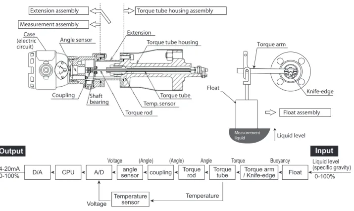
OPERATION PRINCIPLE
One side of the torque tube is fixed onto the torque tube housing with screw. And the other side of the torque tube is assembled with torque arm, which is supported at the knife-edge supporting point. When installing or using the level mea-surement, suspend the float on the edge of the torque arm, and then the torque tube will be twisted by the float's weight. Use the level measurement in this condition.
When process liquid level changes, buoyancy will generate on the float according to the “Principle of Archimedes”. (Dis-placement type float is heavy. Therefore, float dis(Dis-placement may not change the level despite of the liquid level change. In general, it is designed as to be “generated buoyancy of liquid level at 100% < float mass”). The proportionally generated buoyancy to the level, converts into torque by torque arm/knife-edge which suspends the float, and to the torque tube. Torque tube functions as to enclose the process liquid and as torsion spring function, and converts torque into angle dis-placement. This angle displacement transfers through torque rod and coupling, and detected by the angle displacement sensor. Then, it will be converted into liquid level signal by A/D converter, and sent it to CPU.
In case the process liquid contacts with torque tube, the shearing module of the torque tube material will be changed by liquid temperature, and then changes the torsional spring constant, and generates the output shift. To compensate the out-put shift, which generates by liquid temperature, temperature around the torque tube is detected by the temperature sensor, converted into temperature signal by A/D converter and then sent to CPU.
These liquid level signal and temperature signal are computed by CPU, and become digital signal based on each config-ured range by SFC. This computed value will be converted into 4 to 20mADC analog signal with D/A converter and will be output.
Moreover, model SLX is provided parameters to compensate the output shift which generates by liquid temperature. (Default parameters are set at shipment, can be set using SFC later.)
Figure 1 Model SLX - Structure of signal route and signal block diagram Torque arm Float Knife-edge Case Coupling Shaft bearing Torque rod Temp. sensor Torque tube Angle sensor Extension
Torque tube housing Extension assembly
Measurement assembly
Torque tube housing assembly
Float assembly Liquid level Measurement liquid (electric circuit) 4-20mA 0-100% Liquid level (specific gravity) 0-100% angle sensor A/D CPU
D/A coupling Torquerod Torquetube / Knife-edgeTorque arm Float
Output Input
Temperature
sensor Temperature
Voltage
FUNCTIONAL SPECIFICATIONS
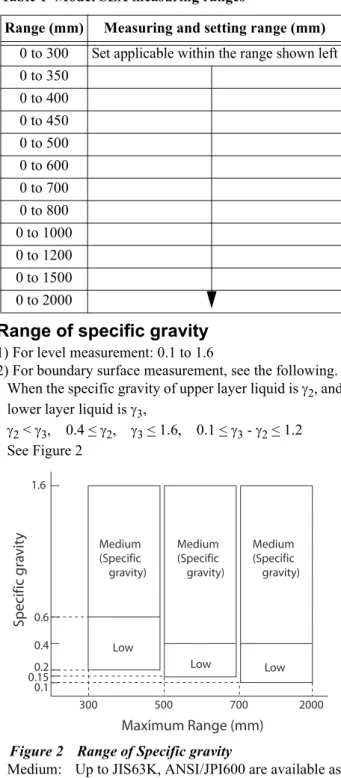
Measuring range.
Range of specific gravity
1) For level measurement: 0.1 to 1.6
2) For boundary surface measurement, see the following. When the specific gravity of upper layer liquid is 2, and lower layer liquid is 3,
2 < 3, 0.4 < 2, 3 < 1.6, 0.1 < 3 - 2 < 1.2 See Figure 2
Figure 2 Range of Specific gravity
Medium: Up to JIS63K, ANSI/JPI600 are available as standard
Low: Up to JIS30K, ANSI/JPI300 are available as standard
If a range beyond those listed here is required, please consult an Azbil Corp. sales representative.
For details, see Table 4 and Table 5.
Output / Communication
Analog output (4 to 20mA DC, min. 3.8mA, max. 20.8mA) Digital output (DE protocol)
Burn-out on failure
(Three optional directions can be selected) No output burnout
Output burnout to upscale (over 20.8mA) Output burnout to down-scale (under 3.8mA)
Supply voltage and load resistance
18.5 to 45V DC. A load resistance of 250 or more is necessary in a loop. See Figure 3.
Figure 3 Power supply voltage / load resistance
Note) For communication with SFC, a load resistance of 250 or more is required.
Stability against supply voltage change
± 0.005% F.S./V
Damping time
Selectable from 0 to 100 sec. in increments of ten
Lightening protection characteristics
Voltage surge wave, maximum: 12 kV Current surge wave, maximum: 1000 A
Operating pressure
-101.3 kPa to each flange rating
Pressure (Up to JIS63K, ANSI/JP600#, can be extended to ANSI/JIS1900# with certain conditions)
See Table 4 and Table 5.
Operating humidity
5 to 100%RH Table 1 Model SLX measuring ranges
Range (mm) Measuring and setting range (mm) 0 to 300 Set applicable within the range shown left 0 to 350 0 to 400 0 to 450 0 to 500 0 to 600 0 to 700 0 to 800 0 to 1000 0 to 1200 0 to 1500 0 to 2000 1.6 0.6 0.4 0.2 0.15 0.1 300 500 700 2000 Specific gr a vit y Medium (Specific gravity) Medium (Specific gravity) Medium (Specific gravity) Low Low Low Maximum Range (mm) 1467 500 250 0 13.0 18.5 24 45 Operating Range R=0.0218E-13 L oad Resistanc e Supply Voltage (DC V)
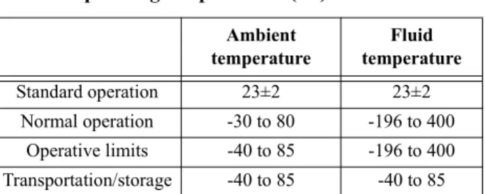
Operating temperatures
For explosion-proof type or with these having the digital meter option, the temperature ranges are as follows:
With digital indicator (option):
Normal operating range: -20 to 70°C Operative limits: -30 to 80°CJIS flameproof type:
Ambient temperature: -20 to 55°CFigure 4 For liquid level of boiler application and boundary surface measurement
Figure 5 For liquid level measurement other than boiler application
PHYSICAL SPECIFICATIONS
Material
See “Table 6 Material” on page 5.
Case finish
Case
Light beige (Munsell 4Y7.2/1.3)
Cover
Dark beige (Munsell 10YR4.7/0.5)
Weight
Approx. 28 kg (For model SLX110-10551E131-11X-X)
Enclosure rating
Equivalent IEC IP66 / NEMA 4X / JIS C 0920 Watertight
Explosion proof
JIS flameproof (Exd IIC T3, Exd IIC T4, Exd IIC T5, Exd IIC T6)
Note) 1. When selecting explosion-proof specifica-tions, please carefully read the following: Industrial Safety Laboratory's Technical Guideline/Factory Explosion-proof Elec-tric Facility Guide (Gas Explosion Proof-ing 1994), published by Industrial Safety Engineering Institute
Note) 2. When making changes to an existing facil-ity, abide by the explosion proofing con-struction of the existing devices.
Example: d2G4 model SLX: ExdIICT4
Figure 6 Allowable external temperature Table 2 Operating temperatures (°C)
Ambient temperature Fluid temperature Standard operation 23±2 23±2 Normal operation -30 to 80 -196 to 400 Operative limits -40 to 85 -196 to 400 Transportation/storage -40 to 85 -40 to 85 600 500 400 300 200 100 -100 -200 0 (0, -196) (50, 400) (50, 200) (80, 80) Long Extension (Other material: U, M) Standard Extension (Other material: A, E, D, W) (-30, -30) -30 -20 -10 0 10 20 30 40 50 60 70 80 F luid Temper atur e ( C) Ambient Temperature ( C) 600 500 400 300 200 100 -100 -200 0 (0, -196) Long Extension (Other material: U, M) Standard Extension (Other material: A, E, D, W) (-30, -30) -30 -20 -10 0 10 20 30 40 50 60 70 80 F luid Temper atur e ( C) Ambient Temperature ( C)
Table 3 Temperature classifications for explosion-proof Temperature level Maximum allowable external temperature* Atmospheric ignition temperature T3 +135°C to 200°C Over +200°C T4 +100°C to 135°C Over +135°C T5 +85°C to 100°C Over +100°C T6 85°C or less Over +85°C
* "Maximum allowable external temperature" is the temperature of this part
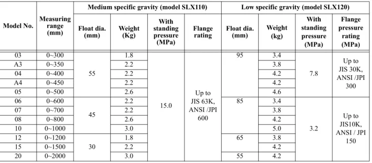
Note) The float weight in the above table is for liquid level application. For interface or hyarometer applications, below conditions will apply: 1. Medium specific gravity (model SLX110): Identical to the figures above,
2. Low specific gravity application (model SLX120): Depends on customer's specifications. (Weight for liq-uid level specifications will be the minimum and it will increase depending on customer's specifications)
Table 4 Float test pressure - Material: SUS316L
Model No. Measuring range (mm)
Medium specific gravity (model SLX110) Low specific gravity (model SLX120) Float dia. (mm) Weight (Kg) With standing pressure (MPa) Flange
rating Float dia. (mm) Weight (kg)
With standing pressure (MPa) Flange pressure rating (MPa) 03 0~300 55 1.8 15.0 Up to JIS 63K, ANSI /JPI 600 95 3.4 7.8 Up to JIS 30K, ANSI /JPI 300 A3 0~350 2.2 3.8 04 0~400 2.2 4.2 A4 0~450 2.2 4.2 05 0~500 2.6 4.6 06 0~600 45 2.2 85 3.4 3.2 Up to JIS10K, ANSI / JPI 150 07 0~700 2.2 3.8 08 0~800 2.6 4.2 10 0~1000 3.0 5.0 12 0~1200 30 1.8 65 3.8 15 0~1500 2.2 4.2 20 0~2000 3.0 55 4.2
Table 5 Float test pressure - Material: Hastelloy C
Model No. Measuring range (mm)
Medium specific gravity (model SLX110) Low specific gravity (model SLX120) Float dia. (mm) Weight (Kg) With standing pressure (MPa) Flange
rating Float dia. (mm) Weight (kg)
With standing pressure (MPa) Flange pressure rating (MPa) 03 0~300 55 1.8 7.8 Up to JIS 30K, ANSI / JPI 300 95 3.8 7.8 Up to JIS30K, ANSI /JPI 300 A3 0~350 2.2 3.4 04 0~400 2.2 3.8 A4 0~450 2.2 4.2 05 0~500 2.6 4.2 06 0~600 45 2.2 85 4.2 3.2 Up to JIS10K, ANSI / JPI 150 07 0~700 2.2 4.6 08 0~800 2.6 5.0 10 0~1000 3.0 5.0 12 0~1200 30 1.8 65 3.4 15 0~1500 2.2 4.2 20 0~2000 3.0 55 4.2
Table 6 Material
Model (temp. range) PartU M A E D W
(350 to 400°C) (200 to 350°C) (0 to 200°C) (0 to 200°C) (-196 to 0°C)*i
Note) *i. Available at the range of 0 to 200°C.
(-40 to 200°C)
Housing Aluminum alloy
Torque tube inconel SUS316L Hastelloy C
Bonnet / chamber Carbon steel (SFVC2A), SUS304, SUS316, SUS316L*ii
Note) *ii. If the optional code is “D”, carbon steel cannot be selected.
SUS316L
Float SUS316L Hastelloy C
Bolt Chromium-Molydbenum steel (SNB7) SUS304
Gasket Spring type (Semi-metallic, Filler material: Graphite)
Extension SUS304 (Long) SUS304 (Standard)
INSTALLATION
Electrical conduit
G½ internal thread, ½NPT internal thread (JIS flameproof is not applicable)
Grounding
Resistance 100 max.
Wiring connection
Wiring terminals screw (M4, SUS304)
Process connection
Flange
External chamber type
Connection Side - Side Side - Bottom Top - Side Top - Bottom Flange size
2 in. or 1½ in. RF (ANSI / JPI 600) 2 in. or 1½ in. RTJ (ANSI/JPI 600)
Internal float type
Connection Top Flange size 3, 4, or 5 in. RF (ANSI/JPI 600) 3 or 4 in. RTJ (ANSI/JPI 600)
PERFORMANCE
Accuracy rating
(at load correction under standard operating condition) +/-0.5% F.S. (for specific gravity, see Figure 2)
Ambient temperature characteristics
(Ambient temperature range: -30 to 80°C, note1) Zero shift:
±
(1.5 × )% F.S. / 55°CSpan shift:
±
(1.5 × )% F.S. / 55°CFluid temperature characteristics
(Fluid temperature range: -196 to 400°C, note 1 and 2) Zero shift:
±
(1.5 × )% F.S. / 55°CSpan shift:
±
(1.0 × )% F.S. / 55°CNote) 1) Correction factor “” changes depending on the mass of measured fluid displaced by float “Mf” when liquid level changes from 0 to 100%. (In case model number is model SLX110, and its measurement range is 300 mm, and specific gravity is 1, “” will be 1.)
Wherein:
D: Float diameter (mm)
H: measuring range (Float length is standard, mm)
: Specific gravity of measuring liquid std:Standard density, std = 1 (g/cm3) : Circle ratio
Note) 2) Only for liquid surface measurement, when temperature correction coefficient: a variable parameter to reduce the operating influence from the process temperature, is 1.0 (default value at shipment) (Not applicable for bound-ary surface level measurement)
709 Mf ---= Mf 4 D 2 H std10–3 1 5.76 10+ –7D2 std ---=
OPTIONAL SPECIFICATIONS
Corrosion-resistant finish
Standard
Baked acrylic finishCorrosion-resistant finish
Baked acrylic finish, fungus-proof finishCorrosion-proof finish
Baked epoxy finish, fungus-proof finish
Built-in indicator
• Digital LCD indicator (optional) • Digital actual scale (SI unit) available • Liquid level display (%, mm)
• Specific gravity display
• Available to set from -3000 to 3100 (limit of resolution is 0.1) (4.5 digits) arbitrary. For actual scale, specify the following items when ordering.
• Actual scale range • Actual scale unit (mm)
Each setting are executed using SFC. (However, version 8.0 or later)
Elbow
This is an adaptor to match the electric conduit connection to field wiring conditions, from horizontal to vertical visa versa. One or two can be selected depending on the field installation requirements.
Oil-free / Water-free treatment (only for
SUS material)
Measuring range of 1000 mm or less:
Delivered after eliminating oil and water from wetted sur-face.
Oil-free treatment (only for SUS material)
Measuring range of 1000 mm or less:
Delivered after eliminating oil from wetted surface.
Test report
This report gives the results of testing, including the exter-nal appearance of the liquid level meter, input / output characteristics (3 points), insulation resistance and with-standing voltage tests.
Five points check
The measuring point of input / output characteristics described on the test report is changed from 3 points (0, 50, 100%) to 5 points (0, 25, 50, 75, 100%)
Traceability certificate
This report consists of three parts; a measurement manage-ment system chart, a calibration certificate and a test report.
Mil sheet
Test results of chemical composition, heat treating condi-tions and mechanical properties of main materials (torque tube housing, bonnet, chamber) will be submitted as certif-icate.
Color check
Result of color check penetration test for welding faults on main materials (bonnet, chamber) will be submitted as cer-tificate.
Without float
(Please contact to sales representative) Float will not be provided.
Please specify if reusing an existing Azbil Corporation's float having the model number NQ31, NQI21, KQP1, KFL00-1, NQP31 or NQP21.
Without chamber
(Please contact to sales representative) Chamber will not be provided.
Please specify if reusing an existing chamber having the model number NQI31, NQI21, KQP1, KFL 00-1, NQP31 or NQP21.
SEMI-STANDARD SPECIFICATIONS
1. Stainless steel bolt (Y131):
For this feature, SUS304 bolts are used for main body assembly. This will be a certified product under High Pressure Gas Law. If the connecting size is JIS10K, NASI150 or JPI150, please consult an Azbil Corp. repre-sentative.
2. Silver corrosion proof (acrylic) paint
(Y138D)
For the prevention of temperature rise by sunlight or radiation heat, as well as protection against corrosive atmosphere. (Note: This does not apply to alkali atmo-sphere)
3. High pressure gas certification (Y2054)
Please refer to the following for scope of manufacture: Scope of liquid level instrument manufacture as certified by Minister for high pressure gas types:
1)-1 Title of certification: Liquid level measurement, float type (including welding construction) 1)-2 Scope of certified specifications:
Refer to Table 7 "Scope of certified specifications" for design temperatures, pressures and connecting sizes. 1)-3 The listing in Table 7 shows scope of certified
spec-ifications, not a scope of certified liquid level meter manufacturing. The scope of manufacture of the certified liquid level meter is within the tempera-tures and pressures listed in the Spec. Sheet.
Note) * When using SF440A. However, the standard material is SFVC2A, temperature will be “0°C or higher”.
Attention in usage
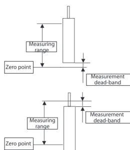
• Azbil Corporation's standard Displacement type level transmitter measurement range is set equivalent to float length H. Therefore, it will be unsuitable when detecting the levels around 0% or 100% (at normal operation), or when continuous output of 4mA or less or 20mA or more is needed.
• When conducting the actual liquid adjustment (filling adjustment) after installing the displacement type level transmitter at the job site, be sure to set the float bottom to zero point (reference point at 0% liquid level). (Struc-turally, if the measurement fluid is not in contact with float, output will not change.)
If other than the float bottom is set to zero point (refer-ence point at 0% liquid level), it may cause the measure-ment dead-band at the measuremeasure-ment range of lower limit (or upper limit), or may cause output linearity error.
Figure 7 Appropriate way of adjustment: Set float bottom at zero point
Figure 8 Inappropriate way of adjustment: set other than the float bottom at zero point
SFC Operation
Parameter setting
(1) Damping: 0~100 sec.(2) Specific gravity: 0.1~1.6 *Note (3) Burnout: NON, UP, DOWN
(4) Span: Set freely within specified range
Calibration
1. Zero adjustment *1 2. Span adjustment 3. Exact adjustment *2 Table 7 Scope of certified specifications
Certific
ate No. MAB-342-0-2
Type of equipm ent Other accessories D es cri p tio n (T yp e) Material Design temperature De si gn pr essur e (M pa) Conne ct in g di a.(A) Ot h ers
Class Group Max. °C Min.°C
Li qu id le ve l met er (B uoy anc y t ype ) Carbon steel G4 450 -10 * Under 6.4 Under 125 Stain-less steel G1 400 -196 Under 6.4 Under 125 G4 800 -269 Under 6.4 Under 125 G6 800 -196 Under 6.4 Under 125 Zero point Measuring
range Float length H
Measuring range Zero point Zero point Measurement dead-band Measurement dead-band Measuring range
Note *1) Make sure that this is done after completing instal-lation at the site.
*2) Match the liquid level measurement output with what is being indicated in the glass gauge. Zero can be adjusted to be set to a point anywhere between 0-100% of the range to match.
Display on SFC screen
1. Input liquid level2. PV value
3. Torque tube temperature 4. Instrument temperature
Calibration
Proofing by SFC using a weight is possible.
Others
Self-diagnostic functions
External adjustment
Use screwdriver (flat screwdriver) from external side of instrument. Zero, span and damping adjustments are possible. Built-in indicator must be selected to use this adjustment.
Note) Change of specific gravity range
• It is necessary to define the specific gravity of the liquid to be measured in order to manufacture the model SLX correctly. However, range change with an SFC will suffice for range set-ting change for the ranges listed below.
• The scope of range change by SFC depends on the float size for medium specific gravity range (model SLX110) / or low specific gravity range (model SLX120).
Also, note that there is a limitation on boundary surface mea-surement (hydrometer) specifications for the low specific grav-ity meter (model SLX120).
1. Medium specific gravity (model SLX110):
1-1. For liquid level measurement specifications, range change is possible within the ‘Specific Gravity Range’ as given in Table 8 below.
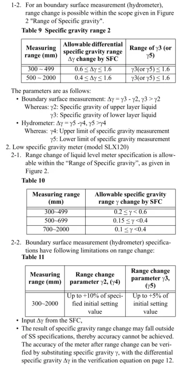
1-2. For an boundary surface measurement (hydrometer), range change is possible within the scope given in Figure 2 "Range of Specific gravity".
The parameters are as follows:
• Boundary surface measurement: = 3 - 2, 3 > 2 Whereas: 2: Specific gravity of upper layer liquid
3: Specific gravity of lower layer liquid • Hydrometer: = 5 -4, 5 >4
Whereas: 4: Upper limit of specific gravity measurement
5: Lower limit of specific gravity measurement 2. Low specific gravity meter (model SLX120)
2-1. Range change of liquid level meter specification is allow-able within the “Range of Specific gravity”, as given in Figure 2.
2-2. Boundary surface measurement (hydrometer) specifica-tions have following limitaspecifica-tions on range change:
• Input from the SFC,
• The result of specific gravity range change may fall outside of SS specifications, thereby accuracy cannot be achieved. The accuracy of the meter after range change can be veri-fied by substituting specific gravity , with the differential specific gravity in the verification equation on page 12. Table 8 Specific gravity range 1
Measuring range (mm)
Allowable specific gravity range
change by SFC 300 ~ 499 0.6 < <1.6 500 ~ 2000 0.4 < < 1.6Table 9 Specific gravity range 2 Measuring
range (mm)
Allowable differential specific gravity range change by SFC Range of 3 (or 5) 300 ~ 499 0.6 < < 1.6 3(or 5) < 1.6 500 ~ 2000 0.4 < < 1.6 3(or 5) < 1.6 Table 10 Measuring range
(mm) Allowable specific gravity range change by SFC
300~499 0.2 < < 0.6
500~699 0.15 < <0.4
700~2000 0.1 < <0.4
Table 11 Measuring
range (mm) parameter Range change 2, (4)
Range change parameter 3,
(5) 300~2000
Up to +10% of speci-fied initial setting
value
Up to +5% of initial setting
MODEL SELECTION
Basic model number
Selections
Options
(Continued) Medium type for specific gravity (0.4 to 1.6): SLX110
- I II III IV V VI VII VIII - IX X XI - XII Low type for specific gravity (0.1 to 0.4): SLX120 *1
Selections
I II III IV V VI VII VIIII Output/ Communication Analog 4 to 20mA output (Standard) 1
Digital (DE protocol) output *7 2
II Measuring range (mm) 0 to 300 0 3 0 to 350 A 3 0 to 400 0 4 0 to 450 A 4 0 to 500 0 5 0 to 600 0 6 0 to 700 0 7 0 to 800 0 8 0 to 1000 1 0 0 to 1200 1 2 0 to 1500 1 5 0 to 2000 2 0 Others X X
III Connection External type Side – Side 1
External type Side – Bottom 2
External type Top – Bottom 3
External type Top – Side 4
Internal Top L1 length is required when ordering 5
Others X
IV Main Materials Bonnet/ Chamber Torque tube Housing (TH)
Carbon steel Carbon steel (unavailable when temperature 0°C or lower) 1
SUS304 SCS13A 2 SUS316 SCS14A 3 SUS316L SCS16A 4 Others X V Other materials *3 (Temperature range *2)
Torque tube: Inconel (350 to 400°C) U
Torque tube: Inconel (200 to 350°C) M
Torque tube:Inconel(0 to 200°C) A
Torque tube:SUS316L(0 to 200°C) E
Torque tube:SUS316L (-196 to 0°C) *2 D
Torque tube: Hastelloy C (-40 to 200°C) Selection of “4” must be given for “IV material” W
Others X VI Pressure rating (Type of Joint) JIS10K (RF) 1 JIS20K (RF) 2 JIS30K (RF) 3 JIS63K (RF) 4 ANSI150 (RF smoothing) A ANSI150 (RF serration) B ANSI300 (RF smoothing) C ANSI300 (RF serration) D ANSI600 (RF smoothing) E ANSI600 (RTJ) F JPI150 (RF) G JPI300 (RF) H JPI600 (RF) J JPI600 (RTJ) K Others *4) X
VII Flange size 1½ in. (40 mm) For external type 1
2 in. (50 mm) For external type 2
3 in. (80 mm) For internal type (medium type only) 3
4 in. (100 mm) For internal type 4
5 in. (125 mm) *1 For internal type (low type only) 5
Others X
VIII Meter body Left side 1
(Continued from previous page)
Options
*1~10: Refer to page 12.
IX Electrical conduit / Explo-sion-proof approvals
G½ / Watertight X
G½ / JIS Flameproof (ExdsIICT3) with 1 pc. of cable gland 1
G½ / JIS Flameproof (ExdsIICT4) with 1 pc. of cable gland 2
G½ / JIS Flameproof (ExdsIICT5) with 1 pc. of cable gland 3
G½ / JIS Flameproof (ExdsIICT6) with 1 pc. of cable gland 4
G½ / JIS Flameproof (ExdsIICT3) with 2 pcs. of cable gland A
G½ / JIS Flameproof (ExdsIICT4) with 2 pcs. of cable gland B
G½ / JIS Flameproof (ExdsIICT5) with 2 pcs. of cable gland C
G½ / JIS Flameproof (ExdsIICT6) with 2 pcs. of cable gland D
½NPT/ Watertight 5
X Built-in Indicator None (without external adjustment switch / without explosion-proof) X
Scale in % (0 to 100% liner scale) 1
Engineering unit scale (only “mm” unit) 2
XI Finish Standard X
Corrosion-resistant finish A
Corrosion-proof finish B
XII No option X
One elbow (left) 1
One elbow (right) 2
Two elbows 3
Oil-free treatment / water-free treatment (only for SUS material) range = 1000 mm or less 4
Oil-free treatment (only for SUS material) range = 1000 mm or less 5
Test report *10 6
Five points check *10 7
Material certificate 8
Traceability certificate *10 A
Color check B
Without Float *5) C
Note)
*1) For low specific gravity applications or 5B/125A, pressure ratings 4, E, F, J and K cannot be selected. *2) When other material is “D”,
1. Temperature 0 to 200°C is available 2. Element material “1” cannot be selected. *3) Float materials are as follows:
Bolt and nut materials are as follows:
* If Y131 is specified bolt / nut material with * mark can be changed to SUS304 / SUS304
*4) For class 900, contact the Azbil Group representa-tive. Also, class 1500 or higher cannot be man-ufactured.
*5) Specify when reusing Azbil Corporation's existing float. Pay attention to the following matters:
1. The prerequisites for selecting Additional Specifications C are: “Liquid level specifica-tions - medium specific gravity - Azbil Corpo-ration's models NQI31, NQI21,
KQP1, KFL00-1, NQP31 or NQP21 without suffix Z
2. Small diameter float may be delivered due to special design outside of SS specification selec-tion.
3. Please make sure that you confirm the diameter of the existing float to ensure accuracy. • Standard characteristics of model SLX
* The model SLX offers consistent accuracy regardless of liquid level measurement, boundary surface mea-surement or hydrometer applications
• Equation to calculate meter accuracy: •
Wherein:
D: Float diameter (mm)
H: Measuring range (float length, mm) : Specific gravity
std: Standard density, std. = 1 (g/cm3) : Circle ratio
Reference: Equation to calculate buoyancy by float Whereas:
: Density of surrounding (measured) fluid,
V: Volume of surrounding (measured) fluid dis-placed by float,
G: Gravity acceleration,
Mf: Mass weight of fluid displaced by float *6) Specify when reusing a chamber. Pay particular
attention to the following matters:
Please ensure that the model number is one of the following Azbil Corporation's models: NQI31, NQI21, KQP1, KFL00-1, NQP31 or NQP21 without suffix “Z”. If suffix “Z” is speci-fied, the chamber and bonnet connecting size should be 3 in. (nominal) ANSI/JPI50, 300, 600 RF. *7) Please add suffix “Z” to the basic model number for
hydrometer application.
*8) JIS and JPI (except JPI600, RTJ) are applicable to RF.
*9) If a semi-standard model number is specified: Add suffix “Y” and write out the Y number separately. The two Y numbers will be decided by Azbil Cor-poration.
*10) When changing measurement point of input / out-put characteristic written on test report from 3 points (0, 50, 100%) to 5 point (0, 25, 50, 75, 100%), select “7” for option together. Option “7” cannot be selected by itself.
* When ordering, specify the following:
Name of fluid = Type of gas =
Temperature: Normal = °C
Min. = °C
Design temperature = °C
Pressure: Normal = MPa
Max = MPa
Design pressure = MPa Other material Float material
U, M, A, E, D SUS316L
W Hastelloy C
Other material Bolt / nut material
U, M, A, E SNB7 / S45C *
D, W SUS304 / SUS304
Mass of measured fluid displaced by float Mf Mf > 400 400 > Mf > 200 200 > Mf
Accuracy +/- 0.5 +/- 1.0 Outside of
guar-anteed accuracy Mf 4D2H std10–3 1 5.76 10+ –7D2 std --- g = F = V G = Mf G Model SLX10---
Specific gravity (enter to third decimal point) For liquid level meter =
For boundary surface measurement: Upper level liquid = Lower level liquid = For hydrometer:
Range of specific gravity measurement =
Dimension from the bottom of flange to top of float (L1) =
Round off after the decimal point and specify using “mm” unit.
If L1 > 1500 mm, consult with sales representative.
DIMENSIONS
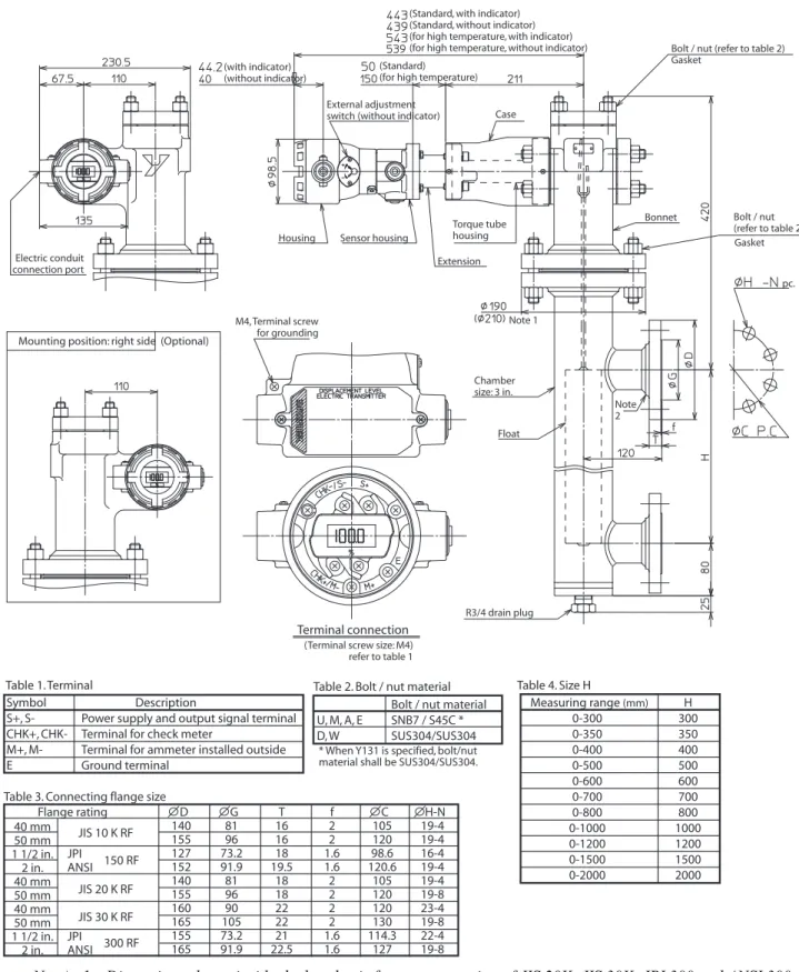
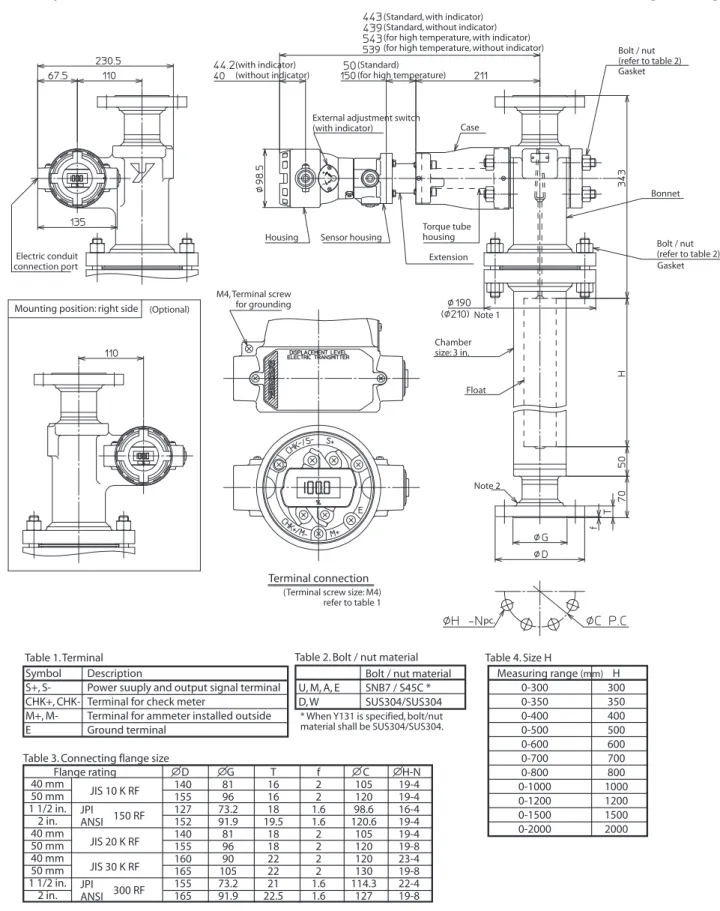
External Float type
S-S: Side - Side [Unit: mm]
Note) 1: Dimensions shown inside the bracket is for pressure rating of JIS 20K, JIS 30K, JPI 300 and ANSI 300. 2: When pressure rating is JIS 10K, hub shown in the figure above will not be provided.
(Standard, with indicator) (Standard, without indicator) (for high temperature, with indicator) (for high temperature, without indicator) (Standard)
(for high temperature) (with indicator)
(without indicator)
Housing Sensor housing
Torque tube housing Extension
Bonnet
Bolt / nut (refer to table 2) Gasket Bolt / nut (refer to table 2) Gasket Chamber size: 3 in. Float Note 2 R3/4 drain plug Terminal connection
(Terminal screw size: M4) refer to table 1 M4, Terminal screw
for grounding Electric conduit
connection port
Mounting position: right side (Optional)
Note 1
Table 1. Terminal Table 2. Bolt / nut material Table 4. Size H Symbol Description
S+, S- Power supply and output signal terminal CHK+, CHK- Terminal for check meter
M+, M- Terminal for ammeter installed outside E Ground terminal
Bolt / nut material U, M, A, E SNB7 / S45C * D, W SUS304/SUS304 Measuring range (mm) H 0-300 300 0-350 350 0-400 400 0-500 500 0-600 600 0-700 700 0-800 800 0-1000 1000 0-1200 1200 0-1500 1500 0-2000 2000 Table 3. Connecting flange size
40 mm 50 mm 1 1/2 in. 2 in. 40 mm 50 mm 40 mm 50 mm 1 1/2 in. 2 in. D 140 155 127 152 140 155 160 165 155 165 G 81 96 73.2 91.9 81 96 90 105 73.2 91.9 T 16 16 18 19.5 18 18 22 22 21 22.5 f 2 2 1.6 1.6 2 2 2 2 1.6 1.6 C 105 120 98.6 120.6 105 120 120 130 114.3 127 H-N 19-4 19-4 16-4 19-4 19-4 19-8 23-4 19-8 22-4 19-8 Flange rating JIS 10 K RF JIS 20 K RF JIS 30 K RF JPI ANSI 150 RF JPI ANSI 300 RF
* When Y131 is specified, bolt/nut material shall be SUS304/SUS304.
External adjustment
switch (without indicator) Case
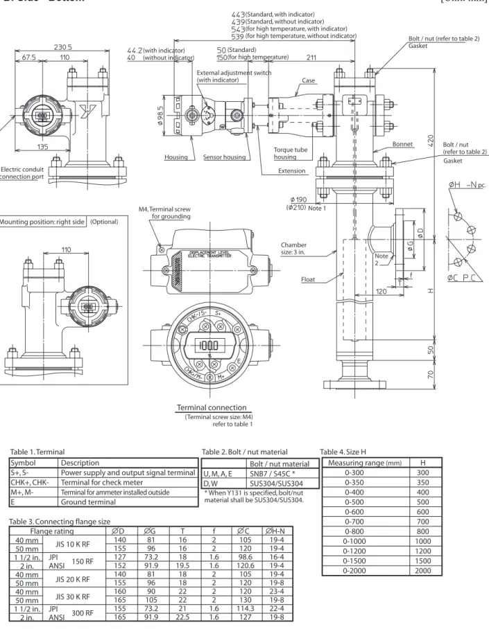
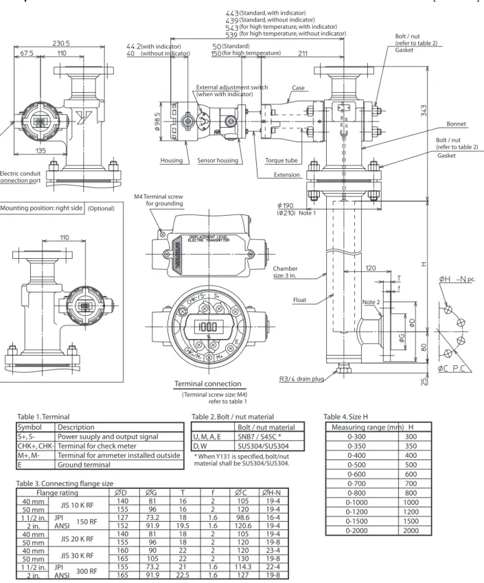
S-B: Side - Bottom [Unit: mm]
Note) 1: Dimensions shown inside the bracket is for pressure rating of JIS 20K, JIS 30K, JPI 300 and ANSI 300. 2: When pressure rating is JIS 10K, hub shown in the figure above will not be provided.
Note 1 (Standard, with indicator) (Standard, without indicator) (for high temperature, with indicator) (for high temperature, without indicator) (Standard)
(for high temperature) (with indicator)
(without indicator)
Housing Sensor housing
Torque tube housing
Extension
Bonnet
Bolt / nut (refer to table 2) Gasket Bolt / nut (refer to table 2) pc. Gasket Chamber size: 3 in. Float Note 2 Terminal connection
(Terminal screw size: M4) refer to table 1 M4, Terminal screw
for grounding Electric conduit
connection port
Mounting position: right side
Table 1. Terminal Table 2. Bolt / nut material Table 4. Size H Symbol Description
S+, S- Power supply and output signal terminal CHK+, CHK- Terminal for check meter
M+, M- Terminal for ammeter installed outside E Ground terminal
Bolt / nut material U, M, A, E SNB7 / S45C * D, W SUS304/SUS304 Measuring range (mm) H 0-300 300 0-350 350 0-400 400 0-500 500 0-600 600 0-700 700 0-800 800 0-1000 1000 0-1200 1200 0-1500 1500 0-2000 2000 Table 3. Connecting flange size
* When Y131 is specified, bolt/nut material shall be SUS304/SUS304.
40 mm 50 mm 1 1/2 in. 2 in. 40 mm 50 mm 40 mm 50 mm 1 1/2 in. 2 in. D 140 155 127 152 140 155 160 165 155 165 G 81 96 73.2 91.9 81 96 90 105 73.2 91.9 T 16 16 18 19.5 18 18 22 22 21 22.5 f 2 2 1.6 1.6 2 2 2 2 1.6 1.6 C 105 120 98.6 120.6 105 120 120 130 114.3 127 H-N 19-4 19-4 16-4 19-4 19-4 19-8 23-4 19-8 22-4 19-8 Flange rating JIS 10 K RF JIS 20 K RF JIS 30 K RF JPI ANSI 150 RF JPI ANSI 300 RF
External adjustment switch
(with indicator) Case
T-B: Top - Bottom [Unit: mm]
Note) 1: Dimensions shown inside the bracket is for pressure rating of JIS 20K, JIS 30K, JPI 300 and ANSI 300. 2: When pressure rating is JIS 10K, hub shown in the figure above will not be provided.
(Standard, with indicator) (Standard, without indicator) (for high temperature, with indicator) (for high temperature, without indicator) (Standard)
(for high temperature) (with indicator)
(without indicator)
Housing Sensor housing
Torque tube housing Extension Bonnet Bolt / nut (refer to table 2) Gasket Bolt / nut (refer to table 2) pc. Gasket Chamber size: 3 in. Float Terminal connection
(Terminal screw size: M4) refer to table 1 M4, Terminal screw
for grounding Electric conduit
connection port
Mounting position: right side
Note 1
Table 1. Terminal Table 2. Bolt / nut material Table 4. Size H Symbol Description
S+, S- Power suuply and output signal terminal CHK+, CHK- Terminal for check meter
M+, M- Terminal for ammeter installed outside E Ground terminal
Bolt / nut material U, M, A, E SNB7 / S45C * D, W SUS304/SUS304 Measuring range (mm) H 0-300 300 0-350 350 0-400 400 0-500 500 0-600 600 0-700 700 0-800 800 0-1000 1000 0-1200 1200 0-1500 1500 0-2000 2000 Table 3. Connecting flange size
* When Y131 is specified, bolt/nut material shall be SUS304/SUS304.
40 mm 50 mm 1 1/2 in. 2 in. 40 mm 50 mm 40 mm 50 mm 1 1/2 in. 2 in. D 140 155 127 152 140 155 160 165 155 165 G 81 96 73.2 91.9 81 96 90 105 73.2 91.9 T 16 16 18 19.5 18 18 22 22 21 22.5 f 2 2 1.6 1.6 2 2 2 2 1.6 1.6 C 105 120 98.6 120.6 105 120 120 130 114.3 127 H-N 19-4 19-4 16-4 19-4 19-4 19-8 23-4 19-8 22-4 19-8 Flange rating JIS 10 K RF JIS 20 K RF JIS 30 K RF JPI ANSI 150 RF JPI ANSI 300 RF
External adjustment switch
(with indicator) Case
(Optional)
T-S: Top - Side [Unit: mm]
Note) 1: Dimensions shown inside the bracket is for pressure rating of JIS 20K, JIS 30K, JPI 300 and ANSI 300. 2: When pressure rating is JIS 10K, hub shown in the figure above will not be provided.
(Standard, with indicator) (Standard, without indicator) (for high temperature, with indicator) (for high temperature, without indicator) (Standard)
(for high temperature) (with indicator)
(without indicator)
Housing Sensor housing Torque tube Extension Bonnet Bolt / nut (refer to table 2) Gasket Bolt / nut (refer to table 2) pc. Gasket Chamber size: 3 in. Float Terminal connection
(Terminal screw size: M4) refer to table 1 M4 Terminal screw
for grounding Electric conduit
connection port
Mounting position: right side
Note 1
drain plug Case External adjustment switch
(when with indicator)
Table 1. Terminal Table 2. Bolt / nut material Table 4. Size H Symbol Description
S+, S- Power suuply and output signal CHK+, CHK- Terminal for check meter
M+, M- Terminal for ammeter installed outside E Ground terminal
Bolt / nut material U, M, A, E SNB7 / S45C * D, W SUS304/SUS304 Measuring range (mm) H 0-300 300 0-350 350 0-400 400 0-500 500 0-600 600 0-700 700 0-800 800 0-1000 1000 0-1200 1200 0-1500 1500 0-2000 2000 Table 3. Connecting flange size
* When Y131 is specified, bolt/nut material shall be SUS304/SUS304.
40 mm 50 mm 1 1/2 in. 2 in. 40 mm 50 mm 40 mm 50 mm 1 1/2 in. 2 in. D 140 155 127 152 140 155 160 165 155 165 G 81 96 73.2 91.9 81 96 90 105 73.2 91.9 T 16 16 18 19.5 18 18 22 22 21 22.5 f 2 2 1.6 1.6 2 2 2 2 1.6 1.6 C 105 120 98.6 120.6 105 120 120 130 114.3 127 H-N 19-4 19-4 16-4 19-4 19-4 19-8 23-4 19-8 22-4 19-8 Flange rating JIS 10 K RF JIS 20 K RF JIS 30 K RF JPI ANSI 150 RF JPI ANSI 300 RF Note 2 ) (Optional)
Internal float type
T: Top connection [Unit: mm]
Note) 1: When pressure rating is JIS 10K, hub shown in the figure above will not be provided.
(Standard, with indicator) (Standard, without indicator) (for high temperature, with indicator) (for high temperature, without indicator) (Standard)
(for high temperature) (with indicator)
(without indicator)
Housing Sensor housing
Torque tube housing Extension Bonnet Bolt / nut (refer to table 2) pc. Gasket Float Terminal connection
(Terminal screw size: M4) refer to table 1 M4, Terminal screw
for grounding Electric conduit
connection port
Mounting position: right side
Note 1
(Refer to table 4) External adjustment switch
(when with indicator)
Table 1. Terminal Table 2. Bolt / nut material Table 4. Size H Symbol Description
S+, S- Power suuply and output signal terminal CHK+, CHK- Terminal for check meter
M+, M- Terminal for ammeter installed outside E Ground terminal
Bolt / nut material U, M, A, E SNB7 / S45C * D, W SUS304/SUS304 Measuring range (mm) H 0-300 300 0-350 350 0-400 400 0-500 500 0-600 600 0-700 700 0-800 800 0-1000 1000 0-1200 1200 0-1500 1500 0-2000 2000 Table 3. Connecting flange size
* When Y131 is specified, bolt/nut material shall be SUS304/SUS304.
80 mm 100 mm 125 mm 3 in. 4 in. 5 in. 80 mm 100 mm 125 mm 80 mm 100 mm 125 mm 3 in. 4 in. 5 in. D 185 210 250 190 229 254 200 225 270 210 240 275 210 254 279 G 126 151 182 127 157.2 185.6 132 160 195 140 160 195 127 157.2 185.6 T 18 18 20 24 24 24 22 24 26 28 32 36 28.5 32 35.5 f 2 2 2 1.6 1.6 1.6 2 2 2 2 2 2 1.6 1.6 1.6 C 150 175 210 152.4 190.5 215.9 160 185 225 170 195 230 168.1 200.2 235 H-N 19-8 19-8 23-8 19-4 19-8 22-8 23-8 23-8 25-8 23-8 25-8 25-8 22-8 22-8 22-8 Flange rating JIS 10K RF JIS 20K RF JIS 30K RF JPI ANSI 150 RF JPI ANSI 300 RF Case (Optional)
Cautions for handling the product
In order to ensure maximum performance from
the product's functions, please handle it properly
while paying attention to the following
precau-tions. Please make sure that you read the
instruc-tion manual of this product before use.
Cautions for installation
WARNING
• When installing, make sure that the gasket
between process connections (flange
connec-tions) does not protrude; otherwise fluid
leak-age or output error may occur.
• Do not operate the instrument beyond the
specified pressure, temperature or conditions.
Could result in damage to the instrument or
fluid leakage which may lead to a serious
accident.
• Wiring installation in an explosion-proof area
must be done in accordance with the
proce-dures stated in the explosion-proof guideline.
For an explosion-proof model with
explo-sion-proof cable gland adaptor, make sure
that an Azbil Corporation-made certified
explosion-proof cable gland adaptor is used.
The cable for wiring should have a 60
°
C
withstanding temperature or higher.
*1Note *1) If temperature class is as listed below, use cables with higher allowable temperature rating:
Temp. class Maximum allowable temperature
T3 70°C
T4 65°C
CAUTION
• Do not use this instrument as a step or
scaf-fold after installation. The instrument may be
damaged and this may result in injury.
• Do not hit indicator's glass window with any
tool or hard object. Broken glass may cause
the injury.
• Make sure that installation has been
per-formed properly. If not, it may result in output
error or violation of industry regulations.
• This instrument is heavy. Be careful on
scaf-fold and wear safety shoes.
WARNING
• Do not perform wiring with wet hands or
while the power supply is on. This may result
in electric shock.
CAUTION
• Make sure that wiring is done properly and
checked thoroughly. Incorrect wiring may
damage the instrument.
• Make sure that the power supply conforms to
specifications and is used properly. An
incor-rect power supply will damage the
instru-ment.
When ordering, please specify each of the
fol-lowing:
1) Model number (attach suffix “Z” to the end
of basic model number for hydrometer.
2) Name of gas or fluid, type of gas, design
temperature, pressure (in particular
instru-ment for High Pressure Gas Law
certifica-tion).
3) Specific gravity of fluid, its pressure,
tem-perature.
4) Dimension from bottom of flange to top of
float (L1)
5) For hydrometer application (range of
spe-cific gravity measurement)
6) For interface measurement application
(spe-cific gravities of upper and lower fluid)
7) Additional specifications.
1st Edition: Issued in June 2001