N A N O E X P R E S S
Open Access
Near-field surface plasmon effects on
Au-double-slit diffraction for polychromatic light
Pin Han
Abstract
The surface plasmon effects on near-field diffraction for polychromatic light are studied. An Au-double-slit is used as the model and Fresnel integral is employed to perform the theoretic analysis. The results are illustrated with numerical examples and they show that, compared with the normal double-slit, the plasmon effect changes the spectral shift from redshift to blueshift and also enhances the intensity peak. This effect can be used in optical data transmission or specific spectral selectors.
Keywords:Surface plasmon; Au-double-slit; Polychromatic light; Near-field; Spectral switch
Background
The study of surface plasmons has gained much attention since the discovery of optical transmission enhancement through subwavelength apertures in metal films [1], which can be explained with the excitation of surface plasmons by the incident optical field on a metal-dielectric interface. For a nanostructure metallic double-slit, these plasmon waves travel toward the slits and couple with the field dir-ectly transmitted through the slits. In this way, the spectra and even the spatial coherence can be modulated [2]. In the past, the spectral changes induced by normal aperture diffraction have been intensively studied, and an interest-ing phenomenon called ‘spectral switch’ was discovered [3]. Also, some related applications were suggested, such as lattice spectroscopy [4] or optical data transmission scheme [5]. Recently, the effect of surface plasmons with Au-double-slit for polychromatic light was studied in the far-field [6], which also showed the spectral switch and was controlled by an electro-optic setup. However, in order to enhance the signal intensity and to use this type of optical device in micro/nanoscale, it is worth investigat-ing the plasmonic effects in the near-field (or the so-called Fresnel zone), which is the topic of this work. The results show that the behavior of near-field diffracted spectral intensity with plasmonic effect differs substantially from that without the effect.
Methods
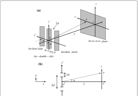
Consider an Au-double-slit with slit width 2b and silt distance 2d, as shown in Figure 1a, and a spatially fully coherent polychromatic field incident from the left, which is modeled as a Gaussian profile
U′ð Þ ¼ω exp −½ðω−ωcÞ2=2σ2
; ð1Þ
whereωcis the center frequency andσis the bandwidth. To excite surface plasmons along the gold-air interface, TM light polarized in x′ polarization as indicated in Figure 1b is used and the field coming out of each slit is
U′Auð Þ ¼ω αþαβexp iksp⋅2d
⋅U′ð Þω ; ð2Þ
whereαis the fraction of field directly transmitted,αβ is the fraction converted into surface plasmons which travel to the other slit where they reappear as a free propa-gating field, and ksp is the surface plasmon polaritons (SPPs) propagation constant. It can be obtained as
ksp¼ω c
εm⋅εd
εmþεd
1=2
; ð3Þ
where εm is the dielectric function of gold and εd is
that of air.εmcan be described with the Drude model as εm¼1− ω2p=ðω2þiωΓÞ
h i
, where ωp2= 1.38 × 10¹⁶s−1and
Γ =1.075 × 10¹⁴ s−1 for gold [7,8]. This model fits quite well with the experimental values for wavelength above 650 nm [7]. For fully spatial coherent light with the Correspondence:[email protected]
Graduate Institute of Precision Engineering, National Chung Hsing University, 250 Kuo Kuang Road, Taichung 402, Taiwan
Au-double-slit, the diffracted light detected at pointP (x,z) in the near-field is
UAuðx;z;ωÞ ¼
expð Þikz 2i ½Fr u2
ffiffiffiffi
ω
p
ð Þ−Fr u1 ffiffiffiffi
ω
p ð Þ þFrðu4pffiffiffiffiωÞ−Frðu3pωffiffiffiffiÞ⋅U′Auð Þω ;
ð4Þ
wherek=ω/cis the wavenumber, Frð Þu ≡
Zu
0
exp iπ2t 2
dt
is the Fresnel integral and we set u1¼pffiffiffiffiffiffiffiffiffiffiffiffi1=πcz −d−b−x
ð Þ , u2¼pffiffiffiffiffiffiffiffiffiffiffiffi1=πczð−dþb−xÞ , u3¼pffiffiffiffiffiffiffiffiffiffiffiffi1=πcz d−b−x
ð Þ, and u4¼pffiffiffiffiffiffiffiffiffiffiffiffi1=πczðdþb−xÞ. Note that the Fresnel approximation is used to derive Equation 4 from the Fresnel diffraction integral [9]. For a normal double-slit, Equation 4 can be used by replacing U′Au(ω) in Equation 2 with U′(ω) in Equation 1. The spectral intensity withIAu(x,z,ω) = |UAu(x,z,ω)|2is
IAuðx;z;ωÞ ¼ð1=4Þj½Fr u2 ffiffiffiffi
ω
p
ð Þ−Frðu1pffiffiffiffiωÞ þFrðu4pffiffiffiffiωÞ −Frðu3pffiffiffiffiωÞαþαβexpiksp⋅2dj2⋅I′ð Þω
≡MAuðx;z;ωÞ⋅I′ð Þω ;
ð5Þ
where from Equation 1, I′(ω) = |U′(ω)|2= exp{−[(ω−
ωc)]2/σ2} is the incident spectrum; MAuðx;z;ωÞ ¼ ð1=4Þ Fr
½j ðu2pffiffiffiffiωÞ−Frðu1pffiffiffiffiωÞ þFrðu4pωffiffiffiffiÞ−Frðu3pωffiffiffiffiÞ½αþαβexp
iksp⋅2d
j2;
the term in front of I′(ω) in Equation 5, is named the modifier because it indicates how I′(ω) is modified to give the diffracted spectrum at P. Note that the modifier contains two parts, the double-slit part (the four Fr(u) terms) and the plasmon part (α+αβexp(iksp ⋅2d)). For normal double-slit, the plasmon part disappears and is replaced by pure apertures; thus, we have
INorðx;z;ωÞ ¼ð1=4Þj½Fr u2 ffiffiffiffi
ω
p
ð Þ−Frðu1pffiffiffiffiωÞ þFrðu4pffiffiffiffiωÞ −Frðu3pffiffiffiffiωÞj2⋅I′ð Þω
¼MNorðx;z;ωÞ⋅I′ð Þω :
ð6Þ
(a)
(b)
Incident lightx′
y′
x
y
z
Incident plane
D etection plane o
Au double− −slits o′
P
2d
2b
2b
2
d
o
′
z
x′
x
P
o
θ E
[image:2.595.56.541.88.425.2]k
Figure 1The Au-double-slit configuration with its corresponding top view.The Au-double-slit configuration for near-field diffraction.
The subscript Nor denotes the normal double-slit situation. A normal double-slit is a completely opaque configuration except the two open slits, which is usually obtained from an infinitely thin, perfect conducting screen; thus, the field inside the slits is the same as the excitation field and Kirchhoff diffraction integral is applicable. The near-field (Fresnel zone) condition is the following: Ncθ2≤1 , where tan (θ) =x/z is the angle between the line O′P and the optic axis O′O as indi-cated in Figure 1b andNc=x2/λczis the Fresnel number at center wavelengthλc. Both Equations 5 and 6 are uti-lized to perform the near-field diffraction calculations; the numerical results and comparisons between the two situations are given in the next section.
Results and discussion
After the formulation, we can illustrate some features of plasmon effect on double-slit diffraction in the near-field with numerical works. Figure 2 shows theI′Au(ω) = |U′Au(ω)|2andI′(ω) = |U′(ω)|2with Equations 1 and 2 for the following parameters: ωc =6π× 1014 s−1, σ =0.3ωc, 2b=d=100 nm, thickness =200 nm,α=0.99, |β| =0.33, arg(β) =2050[2]; the corresponding center wavelength is
λc =1,000 nm and wavelength interval is from 770 to 1,430 nm, lying in the interval to which the Drude model for gold is applicable as mentioned above. It is found from Figure 2 that just behind the double-slit the peak intensity ofI′Au(ω) (solid line) is 1.2 times of that of I′(ω) (dotted line) because of the surface plasmon enhancement and that the peak frequency is blueshifted with an amount of 0.03ωc, as indicated by the arrow above the figure. In the near-field (Fresnel zone), Figure 3a,b,c shows the behavior of all functions including the incident
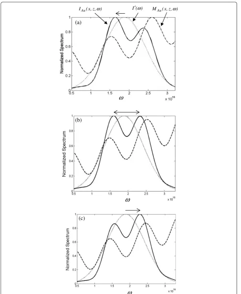
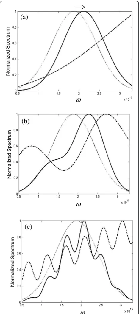
spectrum I′(ω) (dotted line), the modifier MAu(x,z,ω) (dashed line), and the diffracted spectrumIAu(x,z,ω) (solid line) for z =50 um and x =13.3, 13.5, and 13.7 um, re-spectively. First, checking plot (a), the modifier exhibits an oscillating property that depends on the locations of x and influences the incident spectrum and modulates the diffracted spectrum; consequently, there are two peaks in IAu(x,z,ω). It shows that the maximum of the main peak in IAu(x,z,ω) is redshifted (move to lower frequency), as indicated by the arrow above and the amount of the shift is about −0.35σ. Then, in plot (b), we see that the two peaks reach the same height when the lateral position varies from 13.3 to 13.5 um. Finally, in plot (c), when the lateral position varies from 13.5 to 13.7 um, the maximum of the main peak is blueshifted (move to higher frequency) and the amount of the shift is about 0.9σ. From the three plots, we find that the spectral blue or redshift depends on the lateral detec-tion locadetec-tion and it makes a quick transidetec-tion at some specific position as shown in plot (b); this discontinuous spectral shift jump is called the spectral switch [10], which has been studied lately and extensively under different situations. To have a better insight about the lateral spatial effect on the spectral behavior, Figure 4a, b,c shows the spectra forx =0, 10, 20 um, respectively. It is found that only the blueshift is found because the modifier is monotonously increasing forx =0 as shown in Figure 4a. When the value ofxincreases, the oscillat-ing behavior of the modifier becomes more obvious and denser as illustrated in Figure 4b,c, which is reasonable for a Fresnel integral (Cornu spiral) with incremental argument; consequently, the diffraction spectrum is modulated more violently. For the purpose of compari-son between the normal and Au double-slit, Figure 5 illustrates the diffracted spectra for INor(x,z,ω) (solid line) andIAu(x,z,ω) (dashed line) atx=13.7 um andz=50 um. The maximum of each function is indicated by solid and dashed vertical arrows. There are two points that are worth mentioning. First, the amplitude of IAu(x, z,ω) is larger than that of INor(x,z,ω), and it is about 1.18 times that of normal double-slit. Second, the main peak in Au case is blueshifted, while the main peak in normal case is redshifted as indicated by the horizontal arrows. Thus, the effects of surface plasmon in near-field are twofold: both the amplitude enhancement and large spectral shift change can be obtained. This im-port result can give us more flexibility to control the polychromatic light through the plasmonic phenomenon in near-field. It is noted that the behavior of the modifier in Equation 5 depends not only on the de-tection location of P(x,z) but also on the dimension
parameters of the slits b and d because they are
coupled in the argument of the Fresnel integral, for example, u1¼
ffiffiffiffiffiffiffiffiffiffiffiffi
1=πcz
p
−d−b−x
ð Þ, and the plasmon phase
( )
Au I′ ω
( )
I′ω
[image:3.595.57.292.530.711.2]ω
( ) I′
ω
ω
( , , )
Au
M x z
ω
( , , )Au
I x z
ω
ω
ω
(a)
(b)
[image:4.595.55.547.86.687.2](c)
Figure 3Spectral intensity distributions forIAu(x,z,ω) (solid line),MAu(x,z,ω) (dashed line), andI′(ω) (dotted line) forzandx.z=50 um
term exp(iksp ⋅2d) is related with d too. Thus, all these four variablesx, z, b, and dare coupled and contributed to influence the plasmonic spectral behavior.
Conclusions
The plasmonic effect on the diffracted spectral behav-ior of Au-double-slit in the near-field is studied. The analytic formulations for both Au and normal cases are derived by applying Fresnel approximation to the Fresnel diffraction integral. It is found that the incident spectral intensity is enhanced and blueshifted right after the Au-double-slit. Also, the numerical results show that the spectral switch can be found when the lateral positions vary and that the surface plasmons can affect both the magnitude of the diffracted spectral intensity and the spectral shifts, which benefit the control of spectra with plasmons and the potential applications in nano-optic devices.
Competing interests
The author declares that he has no competing interests.
Authors' information
Pin Han is now a professor and the head of the Graduate Institute of Precision Engineering, National Chung Hsing University. His main interests of research are optical engineering, optical design, and light wave propagation.
Acknowledgements
This study was supported by the National Chung Hsing University, Taiwan and the Ministry of Science and Technology of R.O.C. under contract No. NSC 101-2221-E-005 -062 -MY3 and NSC 102-2622-E-005-013-CC3.
Received: 24 June 2014 Accepted: 23 September 2014 Published: 9 October 2014
References
1. Ebbesen TW, Lezec HJ, Ghaemi HF, Thio T, Wolff PA:Extraordinary optical transmission through sub-wavelength hole arrays.Nature1998, 391:667–669.
2. Gan CH, Gbur G, Visser TD:Surface plasmons modulate the spatial coherence of light in Young's interference experiment.Phys Rev Lett2007, 98:043908.
3. Han P:All optical spectral switches.Opt Lett2012,37:2319–2321.
ω
( , , )
Au
I x z
ω
( , , )
Nor
[image:5.595.305.539.87.284.2]I x z
ω
Figure 5Spectral intensity distribution forINor(x,z,ω) (solid line)
andIAu(x,z,ω) (dashed line).
ω
(a)
(b)
ω
(c)
[image:5.595.57.291.88.616.2]ω
Figure 4Spectral intensity distributions for IAu(x,z,ω) (solid
line), MAu(x,z,ω) (dashed line), and I′(ω) (dotted line) for z
4. Han P:Lattice spectroscopy.Opt Lett2009,34:1303–1305.
5. Pu J, Cai C, Nemoto S:Spectral anomalies in Young's double-slit interference experiment.Opt Express2004,12:5131–5139.
6. Verma M, Joshi S, Bisht N, Kandpal HC, Senthilkumaran P, Joseph J:Effect of surface plasmons on spectral switching of polychromatic light with Au-double-slit.Opt Soc Am A2012,29:195–199.
7. Johnson PB, Christy RW:Optical constants of noble metals.Phys Rev B 1972,6:4370–4379.
8. Schmid M, Andrae P, Manley P:Plasmonic and photonic scattering and near fields of nanoparticles.Nanoscale Res Lett2014,9:50.
9. Iizuka K:Elements of Photonics.New York: John Wiley & Sons; 2002. 10. Han P:Spectral switches for a circular aperture with a variable wedge.
J Opt Soc Am A2009,26:473–479.
doi:10.1186/1556-276X-9-561
Cite this article as:Han:Near-field surface plasmon effects on Au-double-slit diffraction for polychromatic light.Nanoscale Research Letters 20149:561.
Submit your manuscript to a
journal and benefi t from:
7 Convenient online submission 7 Rigorous peer review
7 Immediate publication on acceptance 7 Open access: articles freely available online 7 High visibility within the fi eld
7 Retaining the copyright to your article