r
t
'.
Title: 1"""-""""-... ...
~:rhten By:
~~.fSr.ff.-aodel:
Pm~t truRbers:
~-'
~r"d.£:
~~. Users:
Rev
DOCUMENT
I'NFORMA
TION
This pate provides a sequential record of chanees for a Rulti-paee dr_ina. Each "Revision Description" shall also include the appropriate step lUI'ber(s).
(The terR "Extensive Charlies" uy be entered if the loss of history is acceptable). All PBIe8 of this drawine shall carry the sue revision letter as
shown on this paee.
csSO 1'1«()( ~w
lin"',
Nloi MAWTTAT. 0#Ma.'l'"x 1) ... _ ... _
-.HP C2200A/C2202A/C2203A
(bma.n
A-E;QE;Q-ER' .~8 D/H
REVISION HISTORY
-1)
Revision Description Date Approved by:(~e)
! ~ As Issued ' QSn,
7---
0'
"'",
,;: " ns/N.Spohn:::
,:: :, :':: .:: :,:: :' f ,:SPECIFICA TION CONTROL ORA WING
MF
:::
:,':t
j::i:" I,,::
:,
I ': ::: ::: ::..
.: : : .;':" "
'l
<
,":: ::: ': ::' ':: ::: ::1: ::: ,,:
:'
, :::t
FIRST ISSUE
, _-.-' _________
IN
_____
T;...,;;;;;;;;E~R~NA~L=---=--US..;;:::;;...;;;E=__O~N~L;;;;;;...;V~_--J
~~---~---r---r---~---~ ~
l!£\' •
DATE THIS
ISSUE
11/1/88
~G.A-5959-xxxxx-1
PAGE 1 OF76
r/i':9.
HEWLETT
CSSO'
INSTRUCTION SET
Programming Manual
DATE
A
nilS'11/1/88
DlJG.A-5959-xxxxx-1
FIE\'. ISSUE NC!. PAGE 2
a:~
PACKARDesso
INSTRUCTION SET
Programming Manual
r!£)=:~im
P.o. BOX 39, BOlSE,IDAHO 83707,USA
Part No. ?'J???
REV. A
DATE
nBS
ISSt'E
11/1/88
OLIG.
A-5959-xxxxx-l
3
NO. PAGE
Printed in U. S. A. 0788
OF 76
F//':'I
HEWLETT
The following sections have been changed since the HP7937 manual. Section 4. 18 - INITIALIZE MEDIA
Section 6. 11 - 6. 16 NEW UTILITIES
DATE
A THIS
11/1/88
OOG.A-5959-xxxxx-l
Fi'E'\' • ISSUE NO. PAGE
4
PREFACE
[
REV. A
Section 1
RELATED DOCUMENTS
Section 2
INTRODUCTION
Section 3
COMMUNICATION SYSTEM MODEL
CONTENTS
3. 1 Transaction Messages . . . • . . . 9
3. 1. 1 Command Messages . . . . 9
3. 1. 2 Execution Messages . . . • . . . . 9
3. 1. 3 Reporting Messages . . . 1 0 3. 1. 4 Transparent Messages. . . 10
3.2 Device Operation and Transaction Sequence Relationship . . . • . . . 11
3. 3 Power On Sequence . . . 1 3 3. 4 Background Diagnostics. . . 13
3.5 Release Sequence. . . 14
Section 4 Device Commands 4. 1 Locate and Read . . . 16
4. 2 Cold Load Read. . . 1 7 4. 3 Locate and Write. . . 18
4. 4 Set Unit. . . • . . 19
4. 5 Set Volume. . . .. 19
4.6 Set Address. . . • . . . • . . . . 20
4. 7 Set Block Displacement. . . • . • . . . . • . . . • . . . • • . . . 21
4. 8 Set Length. . . • . . . • . • . . . • . . . • . . 22
4.9 Set Burst . . . . • . . . 23
4. 1 0 Set RPS . . . • . . • . . • . . . • . . . 24
4. 11 Set Retry Time . . . • . . . . 25
4. 12 Set Status Mask. . . • . . . • . . . • . . . • . . 26
4. 13 No Op. . . . • . . . • . . . • . . . . 27
4. 14 Set Release. . . .'. . . . • . . . • 28
4. 1 5 Set Options. . . • . . . • • • . . . . • . . • • . . . • . . . 29
4. 16 Set Return Addressing Mode. . . • . . . 29
4.17 Describe . . . • . . . 30
4. 18 Initializ.e Media. . . 33
4. 19 Spare Block. . . 34
DATE
nils
11/1/88
WO.ISSUE NO.
A-5959-xxxxx-l
PAGE5
or
76r/i:t
HEWLETT
REV. A
4.20 Locate and Verify . . . 35
4.21 Copy Data . . . • . . . ' . . . '. . . 36
4.22 Release . . . • • • . . . . 0 • 0 0 0 0 0 • • • • • • • 0 0 • • • • • • • • • • 37 4.23 Release Denied . . . 0 . . . 0 • 0 • • • • • • • • • • • • • • 0 • 0 • 0 • • 0 • 0 38 4.24 Initiate Utility . . . 0 • • • • 0 • • • • • • • 0 • • • • • • • • • • • • • • 0 • • • 39 4.25 Initiate Diagnostics .. ' 0 • • • • • • • • 0 0 • • • 0 • • • 0 • • • • • • • • 0 • 0 • • • • 40 4.26 Request Status . . . 0 . 0 • • • • 0 0 ' . . . 0 • • • • • • • • • 41 Section 5 TRANSPARENT COMMANDS 5. 1 Universal Device Clear . . . . 0 • • • • • • • • • • • • 43 5. 2 Selected Device Clear . . . 44
5.3 Channel Independent Clear . . . 45
5.4 Cancel. . . . 0 46 5. 5 Loopback. . . 47
5.6 HPIB Parity Checking . . . 48
5. 7 Identify. . . 49
Section 6 UTILITIES 6.1 Read Drive Tables Utility . . . • . . . . 53
6.2 Read Run-Time Log Utility . . . 55
6.3 Read ERT Log Utility . . . 57
6.4 Read Fault Log Utility . . . . ~ . . . 59
6.5 Clear Logs Utility . . . 62
6.6 Error Rate Tests . . . 63
6.6. 1 Command Modifiers . . . 63
6.6.2 Specific Tests . . . 0 • • • • • • • • 64 6. 7 Butterfly Seek Utility . . . 0 • • 0 • • • • • • • • • 66 6. 8 Preset Drive Utility . . . 67
6. 9 Read Full Sector . . . 68
6. 10 Read Revision Numbers . . . 0 0 • 0 0 0 • 0 0 0 • • • • • • 0 • • • • 0 0 0 0 • • 0 • • 70 6. 11 Diagnostic Read Utility. . . •• 0 0 0 • • • • • • • • • • • • • • 0 • • • • • • 71 6. 12 Diagnostic Write Utility • . . . • • . . 0 • 0 • 0 • 0 • • • • • • • • • • • • 71 6. 13 Reset Cache Statistics . . . . 0 . ' • • • • • • • • • • • • • 0 • • • • • • 0 • • • • • • • 72 6. 14 Read Cache Error Log. . . . 0 73 6. 15 Cache Control. . . • . . . • . 74 6. 16 Set Cache Page Size . . . . 0 • 0 • • • 0 • • • • • • • • • • • • • • • • • • 76
DAtE
nns
11/1/88
OOG.ISSUE NO.
A-5959-xxxxx-l
PAGE6
OF76
rh':W
HEWLETT
[
~
~LA
TED DOCUMENTS
_ _ _ _ _
1~11
.L...!...-J
CS/80 INSTRUCTION SET Programming Manual, Hewlett-Packard, JUL 1982
DATE
A nns
11/1/88
OlJG.A-5959-xxxxx-1
PAGE 7 or76
Fl£\'. ISS'JE NO.
rliDW
HEWLETT
~IN_T_RO_D_U_C_T_IO_N
______________
~lr~Hr,
This document is essentially a re-write of the CS/80 instruction set programming manual, as it applies specifically to the HP C2200A/C2202A/C2203A disk drive.
CS/80 extensions, not covered in the programming manual, are addressed here.
DATE
A nns
11/1/88
D1JG.A-5959-xxxxx-1
PAGE
8
OF76REV. ISSUE NO.
rli:e-
HEWLETT
1~:_C_O_M_M_UN_I_C_A_T_IO_N_S_Y_S_T_EM
__
M_O_D_EL
____
~lrtill"
A general description of the communications system model for the HP C2200A/C2202A/C2203A can
be found in the CS/80 INSTRUCTION SET Programming Manual (see Related Documents).
The descriptions here serve to summarize the function and format of the various messages involved. In addition, this section introduces device start-up, diagnostic and command pipelining concepts.
3.1 TRANSACTION MESSAGES
There are three message types which occur in a normal transaction:
1) Command messages which contain the HP C2200A/C2202A/C2203A opera ting commands
2) Execution messages which transfer data
3) Reporting messages which contain the one-byte pass/fail status (QSTAT) of the transaction.
A fourth message type, transparent, is used to compensate for different types of channels and differences in operating environments.
3.1.1
Command Messages
Command messages are initiated by a host and always go from the host to a device. The contents of the message may vary in length up to 1024 bytes.
3.1.2
Execution Messages
Execution messages are initiated by the drive unless an execution message has already been established by the host.
The direction and significance of the message text depends on the command being executed. Possible execution message contents include:
1) Read Data
2) Write Data
3) Detailed Status Report
4) Diagnostic Inf orma tion
Execution messages are valid only during the execution phase of a transaction which started with a command which calls for an execution message.
DATE
A THIS
11/1/88
~. ISSUE
DI.tG.
A-5959-xxxxx-1
NC. PAGE
9
or76
rh:'l
HEWLETT
The host may cause execution messages to be broken into bursts of smaller messages of uniform length by setting a non -zero burst size.
3.1.3 Reporting Messages
The device initiates reporting messages during: 1) The reporting phase of each transaction
2) Special reporting phases entered for power recovery 3) The service of internal requests
All reporting messages consist of one byte of status information transmitted from the drive to the host. This byte contains the QSTAT pass/fail indication tagged with a message terminator (EOI on HP-IB). The QSTAT byte always reflects the information currently contained in the status report. The only means of clearing the QST A T byte is by (the host) issuing the Request Status command or the Clear command.
The QST A T byte indicates one of three conditions relating to the current transaction:
1) Normal Completion. The requested operation was completed without error. 2) Hard Error. Error information is available. The host must issue a Request
Status command to determine complete transaction status.
3) Power On. The device has just returned from a power failure or some form of operator intervention. Any incomplete transactions were aborted and should be repeated. The host must reconfigure any programmable operating parameters because they have returned to their power-on values.
3.1.4 Transparent Messages
Transparent messages compensate for different types of channels and differences in operating environments.
Transparent messages also include interface specific functions or interface testing. Some device specific messages may be required in order to maintain the integrity of the transaction sequence in specific operating environments.
Interface testing includes Read and Write loopback.
Transparent messages may be initiated by either host or device, and they can be transmitted in either direction. The first byte of the text may be an operating code (opcode) which indicates the purpose of the message. The format of the remainder of the message is a function of the first byte.
DATE
A THIS
11/1/88
REV. ISSUE
IXoIG.
A-5959-xxxxx-1
NO. PAGE 10 OF 76
F,/:W
HEWLETT
3.2 DEVICE OPERATION AND TRANSACTION SEQUENCE
RELA TIONSHIP
When it is idle, the drive is in the command-ready state. When a command message is received, it is buffered, parsed, and validated. If the command and its parameters are valid, the drive enters the execution state and begins to carry out the command. If not, the drive enters the reporting state and prepares an error status report.
In the execution state, the operation requested by the host is performed. If a data transfer is involved, the drive will request an execution message (via the parallel poll on HP-IB) from the host. The execution message is not required for transactions which do not involve a transfer of information. When the requested operation is complete, the drive computes the status of the operation, enters the reporting state, prepares the status reports, and requests a reporting message from the host. The device supplies a one-byte status report (QSTAT) to the host as the text of a reporting message.
DATE
A THIS
11/1/88
R£V. ISSUE
OLIG.
A-5959-xxxxx-1
NO. PAGE
11
OF 76r,,-:w'
HEWLETT
REV.
DEVICE OPERATING STATE DIAGRAM
DECODING
AND Command received
EXECUTION
~~~---~
.,
.~Valid internal
.. It release request
Command
a...----~-'IIDIAGNOSTICS
I
• d-'
recelve
Internal release request
.,.3
seconds idlein Command Ready
diagnostic failure
2 seconds Command
Ready, release pending
Execution
II
Report---I:~:
REPORTINGcompleted ~~~ __ ~ __ ~IJ accepted by
-f
.~ .~ .~.~.~
host Poweron
---'"
Failure
Release
(during report)
complete
t ·
~
·
~
COMMAND READY
.
.~.,.. .~ Release (during Command Ready) complete POWER OFF Command received.. I
RELEASE1-,
2 seconds
i~1
1~2
seconds in Report, release Command Ready, pending release pendingDATE
A THIS ISSUE
11/1/88
DUG. NO.A-5959-xxxxx-1
PAGE12
OF 76r,;-:w
HEWLETT
3.3 POWER ON SEQUENCE
The following power-on sequence will be executed:
1) The drive executes its power-on diagnostic 2) A status report is created
3) The drive enters an interlock reporting state
The drive will remain in this interlock reporting state until the host acCepts the reporting message ,or issues the Clear command. A Set Unit command will be executed, but if the host sends any other CX)mmand, the drive will only accept (not execute) the command. The resultant reporting message will indicate that the drive is still in the power-on state.
If a power-on diagnostic failure has occurred, the status report will not be cleared by the Clear CX)mmand. The host will see the diagnostic failure in the first reporting message returned by the failing drive.
3.4 BACKGROUND DIAGNOSTICS
Background diagnostics are initiated 0.3 seconds after entering the command-ready state, unless a diagnostic failure has occurred or release is pending. A release must be dealt with before the background diagnostics can begin. Once begun, the drive will continue to run the diagnostics until a failure occurs, an internal request for release is detected, or the host issues a command to the drive. A command will cause the drive to abort the background diagnostic and begin execution of the command. This prevents the background diagnostic from interfering with normal channel communications. An internal release request will cause the diagnostics to abort and will start the proper release sequence.
If a failure occurs during the background diagnostic, the drive will:
1) Set the Diagnostic Result bit in the status report 2) Set a hard error into the QST A T byte (QST ATe 1) 3) Enter an interlock reporting state
Once in the interlock reporting state, the drive will not execute any commands issued by the host until the diagnostic failure has been reported. The host must accept the reporting message and then issue the Request Status command. This is the only way that the host can clear the status report. The Clear Command will not clear a diagnostic failure.
Diagnostic results are held in non-volatile memory and a drive which suffers power loss after failing its diagnostic will still be failed when power is restored.
DATE
A THIS
11/1/88
REV. ISSUE
~G.
A-5959-xxxxx-1
NO. PAGE
13
or 76rh:'
HEWLETT
3.5 RELEASE SEQUENCE
The drive will need to go offline in order to respond to the following needs: 1) Error logging routine
2) Auto sparing routine
The release sequence can be initiated by the host via the Release command or, if so configured, the drive can release itself in the following ways:
1) Drive is two seconds in Command Ready state AND a release is pending AND auto release is enabled.
2) Drive is two seconds in Reporting state (normal or unsolicited) AND (a release is pending OR an internal release request is detected) AND release timeout is enabled.
When a request for release is pending, the appropriate Release Request bit will be sent in the drive's status message. In addition, the drive unit number will be placed in the parameter field of the status message, providing this field is not needed by a higher priority error. This ensures that the host will see all release requests during the reporting phase (QST AT-I).
Power may be lost before the drive can be released. When the drive powers up, it will not request release until after the power-on diagnostics have run. However, the drive will request release during the interlock reporting phase.
The exception to this sequence occurs during automatic release; when automatic release is enabled the drive will never request release from the host.
With automatic release enabled and release pending when the Command Ready state is entered, the drive will wait two seconds before releasing itself. If the host issues a command during this interval the command will be executed and the automatic release will not occur. Although the release did not occur, the drive will remember the request and the first time the two-second interval elapses without a command from the host the drive will release itself.
Power may be lost before the drive can release itself. When the drive powers up, it will not attempt to release itself until after it has entered the Command Ready state.
If release timeout is enabled and an internal requirement occurs during background diagnostics, the drive:
1) Aborts background diagnostics
2) Sets the Release Request bit in·the status message 3) Goes to the Reporting state
4) Starts the internal timeout clock 5) Requests a reporting message
DATE
A nils
11/1/88
DlJG.A-5959-xxxxx-1
This sequence puts the drive in an unsolicited reporting state, that is, a reporting state that is not part of a transaction. If the host accepts the reporting message, the hard error QST A T should cause the host to respond with a Request Status command. The status message will alert the host to the request
80 the host should release the drive if possible; if not, the host should issue the Release Denied
command. If the host does not respond to the unsolicited report before the timeout clock expires, the drive will release itself.
If release timeout is enabled and release is ))ending when the Command Ready state is entered, the procedure is similar to that described in the preceding paragraph; the only exception being a two-second wait in Command Ready before going to unsolicited Report. During this interval the drive will accept commands from ihe host and, if possible, execute them.. If the host issues a command which cannot be executed because it involves of the needed release, the command will be aborted and the drive will return a status of release required. This informs the host that the release is no longer simply a request and that the command cannot be executed until the drive is released and serviced. Once the drive has entered the unsolicited Reporting state, commands will no longer be accepted from the host. If the host attempts to send a command, it will fail and a Retransmit error will result. The drive will remain in the unsolicited Reporting state until the host accepts the reporting message or the timeout clock expires. If the host accepts the reporting message, the drive will go to the Command Ready state with release pending. If the timeout clock is disabled, the drive will remain in unsolicited Report until the host accepts the reporting message. The host can clear the release request by issuing the Release Denied command or the Clear command.
When release timeout is enabled, release can also occur during a normal reporting state, that is, a report that occurred as a part of a transaction. If the drive enters Report with release pending and timeout enabled, the host must accept the report within two seconds or release will occur. If the drive
is in normal report and an internal release request occurs, the drive will begin its two-second wait. The host must accept the report during this interval or the drive will release itself.
Once the drive has been released and the requirement has been serviced, the drive will return in either the Reporting or Command Ready state; reporting if the release occurred during a normal report or a failure occurred while the drive was released; Command Ready if the release occurred during an unsolicited report or the Command Ready state. Any attempt by the host to communicate with the drive while it is released will result in a Retransmit error when the drive returns. This informs the host that the attempted transaction failed and should be retried.
DATE
A TH!S
11/1/88
m:v. ISSUE WG. NO.
A-5959-xxxxx-1
PAGE15
OF76
r,,-:w
HEWLETT
~D_e_Vi_c_e_c_o_m_m_a_n_ds
________________
~lr~j.jf'
4.1 LOCATE AND READ
FUNCTION:
Locates the data indicated by the target address and transmits it to the host.
COMMAND FORMAT:
IOPCODE (OOH)
I
DESCRIPTION:
The Locate and Read command is validated during the command phase of the transaction, after which the execution phase may begin.
First the drive locates the data indicated by the target address and performs its error correction function. A failure of any operation up to this point terminates the transaction leaving it in the reporting phase. Once the data is accessible to the host) the drive requests an execution message. If
RPS (Rotational Position Sensing) is enabled) the window size and position relative to the target sector are used to determine when to assert and de-assert requests for messages. When an execution message is established) the data transfer begins.
The length of the total data transfer is the number of bytes specified in a Set Length command included in the message with the Locate and Read command. If set Length is not specified, the power-on or last set length value is used. If Burst mode is enabled, another link is requested when the next burst is available. (RPS is not effective in the burst mode.)
If a data error is encountered in the course of the transfer, the drive is allowed to attempt correction for an interval specified in the Set Retry Time (Complementary) command. If the data is unrecoverable, the drive will determine its most accurate reconstruction of the data and return this to the host. The address of the first sector of any bad data will be included with the status report returned by a Request Status command.
The transfer always contains the amount of data requested by the host unless the host intervenes or a hardware fault occurs. If a hardware fault occurs, the drive will return a single byte (QSTAT-1)
tagged with the message terminator (EOI on HP-IB). The Drive will continue to return this single byte until the host enters the reporting phase of the transaction.
DATE
A
THIS11/1/88
REV. ISSUE D1JG. NO.
A-5959-xxxxx-1
FAGE16
or76
r/i:e
HEWLETT4.2 COLD LOAD READ
FUNCTION:
Used by a host system to bootstrap itself into a higher operating environment from a more primitive state.
COMMAND FORMAT:
IOPCODE (OAH)
I
DESCRIPTION:
Cold Load Read is part of the following unique channel sequence: Clear: Wait for message request: Clear: Send Cold Load Read
The Clear command ensures that the device Complementary command parameters are all in the initial (power-on) states, and the device is in the command-ready state.
The operation of the Cold Load Read is identical to the operation of the Locate and Read ~ommand.
DATE
A THIS
11/1/88
~. ISSUE
IlIG.
A-5959-xxxxx-1
NO. PAGE
17
or 76
rh;1l
HEWLETT
4.3 LOCATE AND WRITE
FUNCTION:
Transfers data from the host to a storage area beginning at the address specified by the target address.
COMMAND FORHAT:
IOPCODE (02H)
I
DESCRIPTION:
This command is the only means available to write data from the host onto the disk media. The opcode is validated during the command phase. If the command is received and decoded correctly, the execution phase commences by locating the area of the media where data is to be written. The address is specified by the Target Address. Using any RPS or burst mode settings, the drive determines when it is ready for data, then requests an execution message. The number of data bytes defined by the power-on or last set length value are accepted and written to the host. The message ends with a message terminator (EOI on HP-IB).
The write verifies a sector prior to writing on any track, whether the track was reached by an internally or externally generated seek. The write may be aborted by hardware problems, failure to verify at least one block on the correct track, or by some host intervention. If the drive's internal write process is abnormally terminated, the disk will sink data until the execution phase is complete. The reporting phase is used to resynchronize the transaction.
DATE
A
THIS11/1/88
REV. lSSU£[ltJG.
A-5959-xxxxx-1
NO. PAGE
18
or 76r/i:'l
HEWLETT
4.4 SET UNIT
COMMAND FORMAT:
IOPCODE (2XH)
I
x
=
Unit Number (X= FH implies Device Controller)
DESCRIPTION:
The drive allows unit 0 and F. Unit F is only used for certain utilities and diagnostics which are compatible with earlier CS80 discs.
4.5 SET VOLUME
COMMAND FORMAT:
IOPCODE (4XH)
I
The value X may range from 0 through 7 and specifies the volume number.
DESCRIPTION:
This command does not apply to the HP C2200A/C2202A/C2203A since it has no removeable media.
DATE
A THIS
11/1/88
REV. ISSIJE ooG. NO.
A-S959-xxxxx-1
PAGE19
or 76r/i:W
HEWLETT
4.6 SET ADDRESS
FUNCTION:
Used to set the value of the target address. Specifies single, or three-vector address mode.
COMMAND FORMAT:
OPCODE (1 XH') PARAM 1 PARAM 2 PARAM 3 PARAM 4
PARAM 5
I
PARAM 6
X=o implies single-vector mode.
Parameters form a singlet 6-byte unsigned binary number.
X=1 implies three-vector mode.
PARAM 1 - PARAM 3
=
cylinder address PARAM 4=
head address PARAM 5 - PARAM 6=
sector addressDESCRIPTION:
The Set Address command is used to set the value of the drive's target address. The target address is then used by all other commands accessing data on the drive. The Set Address power-on value address is address O.
Upon completion of a transaction which uses the target. address) the target address will point to the sector after the last sector accessed during that transaction) whether or not the transaction was successful. The target address can be obtained from the Request Status execution message.
The Target Address is unlike other Complementary parameters in that it is updated by any command which accesses data, and does not revert to a prior value when another accessing command is sent. This allows sequential data accessing.
If an Address Bounds error occurs during a Set Address command, the target address will be set to zero. The target address is also set to zero any time and End of Volume occurs.
DATE
A nus
11/1/88
REV. ISSUE NO. DlJG.
A-5959-xxxxx-l
PAGE 20 OF 76Fli:'l
HEWLETT
4.7 SET BLOCK DISPLACEMENT
FUNCTION:
Adjusts the target address by the number of blocks indicated in the parameter field.
CONNAND
FORMAT:
OPCODE (12H)
PARAM 1
PARAM 2
PARAM 3
PARAM" 4
PARAM 5
PARAM 6
Parameter format: 6-byte, signed, two's complement, binary number
DESCRIPTION:
The block displacement parameter is a double precision signed two's complement number which is added to the current target address. The new target address is tested for bounds violation.
The next accessing command will cause a seek to the new target address.
DATE
A nns
11/1/88
DlJG.A-5959-xxxxx-1
PAGE21
REV. ISSUE NO. OF 76
r//:t
HEWLETT
4.8 SET LENGTH
FUNCTION:
Defines the number of bytes in a data transfer.
COMMAND FORMAT:
OPCODE (18H)
PARAM 1
PARAM 2
PARAM 3
PARAM 4
Parameters are unsigned binary byte values.
DESCRIPTION:
The four bytes following the Set Length opcode contain the byte count of the transfer length. If this field is not included in the command message, the transfer length will be determined by the power-on or last set value. A length specification of all 1 's (the power-on value) implies a transfer siz.e equal to the selected volume. The volume siz.e is determined by the Describe command.
A length specification of all O's will cause the drive to respond to a Real Time command with a Locate only (seek). No data is transferred. A Real Time command executed in this manner does not require an execution message. After this type of seek, no verification of the target block dress is performed.
DATE
A THIS
11/1/88
REV. ISSUE DUG. NO.
A-5959-xxxxx-1
PAGE 22 or 76r/i'3
HEWLETT
BEY.
4.9 SET BURST
FUNCTION:
Activates (and de-activates) burst mode.
CONMAND FORMAT:
I
OPCODE (3XH)
IPARAM 1
x=c
indicates that the last burst only is tagged with a terminator X=D indicates that all bursts are tagged with a terminatorParameters:
PARAM
1=
Number of 256 byte segments in each burstDESCRIPTION:
Set Burst applies only to real-time commands. Multiple execution messages may be used to accomodate certain timing requirements. The host uses this burst value to define the maximum amount of data to be transferred in anyone execution message. The value specified by the Set Length command is then divided by the siz.e of each burst to "lculate the number of execution messages expected. The last burst may be shorter than the others.
Set Burst is disabled at power on.
DATE
A THIS
11/1/88
OOG.4.10 SET RPS
FUNCTION:
Set time-to-target and window-size time intervals for RPS data transfers.
COMMAND FORMAT:
IOPCODE
(39H)
I
PARAM 1
PARAM 2Parameters: PARAM 1
=
time-to-target in hundreds of microseconds PARAM 2=
window size in hundreds of microsecondsDESCRIPTION:
Rotational Position Sensing (RPS) is provided to minimize non-productive channel usage while waiting for the drive to locate the area at which a transfer will begin. Using this feature, the drive will request an execution message containing read or write data only during a period called the RPS window. The window opens at a point in time which precedes the target address by an interval specified as time-to-target, and remains open for a duration specified by window-size. If the host does not respond with an execution message during this window, the execution message request will be
removed until the next time the target address becomes accessible
If PARAM 1 c 0, RPS is disabled and the execution message request will occur upon completion of the
seek operation.
If PARAM 2 >0 (RPS enabled) and PARAM 2· 0, the window will remain open and the execution message request will continue until the host responds with an execution message.
If either of these parameters exceeds the latency time period, it will be treated in the same manner as a zero value.
At power-on, or after a Clear command is executed, RPS is disabled.
DATE
A THIS
11/1/88
WG.A-5959-xxxxx-1
REV. ISSUE NO. PAGE 24 or 76
r//:t
HEWLETT
4.11 SET RETRY TIME
FUNCTION:
Used to set the amount of time available for read and seek retries.
CONNAN D FORMAT:
IOPCODE (3AH>1 PARAM
1 PARAM 2Parameters: PARAH1
DESCRIPTION:
PARAM2
=
Retry time in tens of milliseconds (16 bit, unsigned, binary number)Retries are attempted after an un correctable data error is encountered or when an attempted seek fails. The power-on value is equal to the optimal retry time specified by the Describe command. A retry time of 0 causes no read retries to take place. This does not eliminate latencies induced by unrecoverable errors. In general, one latency per read attempt will be observed) once for any . unrecoverable error.
REV,
A controller may impose a minimum allowable retry time. If the current retry time is set below the imposed minimum, it will be forced to the minimum value. No error is generated in the process. When specifying retry time the host is specifying the maximum delay between any two bytes of a data transfer over the channel. As this is directly related to channel timeout) the maximum retry time should be set to some value less than the defined channel timeout. Using this rule, it is possible that the maximum retry time could be invoked for each block of a data transfer. This situation would imply such a high error rate as to indicate a hardware problem.
DATE
A nns ISSUE
11/1/88
DlJG.
A-5959-xxxxx-l
NO. PAGE
25
OF76
r//:t
HEWLETT
4.12 SET STATUS MASK
FUNCTION:
Allows masking of error conditions reported by the Request Status (Diagnostic) command.
COMMAND FORMAT:
IOPCODE
(3EH)I
PARAM 1
PARAM 2
PARAM 3
PARAM 4
I
I
PARAM 5
I
PARAM 6
I
PARAM 7
I
PARAM B
I
Parameter format: Bit positions in parameter bytes correspondto error bit positions in the error reporting fields of the status report (see Table
2-25,
CS/BO instruction set programming manual).DESCRIPTION:
If a bit is set to one, it indicates that error is to be masked.
This opcode is followed by 8 bytes containing the status bits to be masked. All error conditions except fault errors may be masked.
If any non-maskable status bits are set, a Parameter Bounds error will result. The power-on value has no error conditions masked.
The masked bits will not be reported by either Request Status or QST A T. If a status bit is not masked, it reports a hard error (QST A T== 1) when set. The only exception to this is the Power Fail status bit. This bit reports a power-on status (QST AT==2) when set.
DATE
A THIS
11/1/88
REV. ISSUE
l'lG.
A-5959-xxxxx-1
NO. PAGE
26
OF 76rh:W
HEWLETT
4.13 NO OP
FUNCTION:
Causes the drive to disregard this message byte.
COMMAND FORMAT:
IOPCODE (34H)
I
D£SCRI PTION:
This byte is disregarded if it appears as an opcode in a command message. It may be useful to align messages to word boundaries. Then again, it may not.
DATE
A THIS
11/1/88
4.14 SET RELEASE
FUNCTION:
Used by the host to set specific options.
COMMAND FORMAT:
IOPCODE
(3BH>1
PARAM 1Pa ramete r 1"0 rna t : PARAM
= TZOOOOOOB
T = 1 Suppress release timeout
Z
=
1 Release automatically during idle timeDESCRIPTION:
The Set Release command allows the host to define how the device will respond to an internal release request. There are four ways the device can be configured .. The first is with the release timeout enabled and automatic release disabled (T-O,Z-O). This configuration will impose a two-second limit on the time the device will remain in the reporting phase requesting release. If the two-second interval elapses without any response from the the host, the device will release itself. The host can prevent the device from ever releasing itself by disabling both the timeout clock and automatic release (T-l,z-O). In this, the second case, the device will still enter the unsolicited reporting phase to request release but will be unable to release itself. A Release command issued by the host is the only way the device can be released when this configuration is used.
The third configuration enables automatic release (T-l,Z-1) and allows the device to release itself without requesting release from the host. If release is pending, the device will wait in the command-ready state for two seconds. If no channel activity occurs during this period, the device will release itself. The final configuration also enables automatic release (Y-O,Z-O but, with timeout enabled as well, automatic release may occur after two seconds in either the command -ready or reporting state.
The power-on values of T and Z are O.
DArE
A THIS
11/1/88
DUG.A-5959-xxxxx-1
REV. ISSUE NO. PAGE
28
or 76r/i:e
HEWLETT
4.15 SET OPTIONS
FUNCTION:
Activates (and de-activates) burst mode.
COMMAND
FORMAT:
IOPCOOE (38H)
IPARAM 1
DESCRIPTION:
This command is not implemented.
4.16 SET RETURN ADDRESSING MODE
FUNCTION:
Allows the host to specify the type of address (single or three-vector) returned in the Request Status message.
COMMAND
FORMAT:
IOPCODE (48H)
I
PARAM
1Parameter format: PAR AM 1
=
0Single-vector mode
PARAM 1
=
1Three-vector mode
DESCRIPTION:
This command allows the host to specify the type of address (single or three-vector) to be returned in the Request Status message. This allows the host to select either the same address mode defined in the Set Address command or use a different mode. The selection of the type of address returned in the Request Status message is determined by the host and the specific type of device involved) providing the drive supports the address mode selected.
The power-on value is 0 (single-vector~
DATE
A nilS
11/1/88
DlJG.A-5959-xxxxx-l
REV. ISSUE NO. PAGE
29
OF 76r/i:'l
HEWLETT
4.17 DESCRIBE FOR HP
C2200A/C2202A/C2203A
FUNCTION
Returns (in an execution message) up to 256 bytes of information concerning device type and characteristics.
CO",,,,MAND FORMAT:
IOPCODE (35H)
I
DESCRIPTION:
This command provides enough information about the drive to allow it to be configured into a system without the host having prior knowledge about this device type. The drive will return a maximum of
256 bytes of information in the execution message.
See table 2-4 of the CS/80 instruction set programming manual for details of the execution message format.
The last byte of this message will be tagged with a message terminator (EOI on HP-IB) so that fewer than 256 bytes may be transmitted. There are three types of description fields returned: the controller field (5 bytes), the unit field (19 bytes), and the volume field (I3 bytes). The format (quantity and sequence) of the description fields returned to the host in an execution message is determined by the unit addressed.
If a selected unit (not the controller) is addressed, the returned sequence format is:
Controller field Unit 0 field Volume 0 field
The unit field describes the addressed unit and the volume field describes the currently specified volume. Each field is returned once per transaction.
If the controller unit is addressed, the returned sequence format is:
Controller field Unit 0 field Volume 0 field
The controller field, unit 0 field and volume 0 field are returned since the drive has only one unit and one volume.
DATE
A
nns11/1/88
REV. ISSUE
000.
A-5959-xxxxx-1
NO. PAGE 30 or 76
r/i':I.
HEWLETT
itf.V •
CONTROLLER FIELD
C1 C2 C3 C4
cs
C1-C2 c Installed unit byte: 1 bit for each unit. (Unit 0 =. LSB) <1>
C3-C4
=
Maximum instantaneous transfer rate in thousands of bytes <1250> per second.C5
=
Controller Type<0> O=Integrated single-unit controller 1=Integrated multi-unit controller 2=Integrated multi-port controller
U1 <0>
U1
UNIT FIELD
U2 U19
=
Generic Device Type O=fixed disk1=Removable disk or combination
2=Tape , fixed block size, random access
U2-U4 = Device number. Represents actual
HP
product number:XX XX XV
<022000> (BCD Coded, 2 digits per byte) -HP
C2200A<022020> (BCD Coded, 2 digits per byte) -
HP
C2202A <022030> (BCD Coded, 2 digits per byte) -HP
C2203Aus-us
<256>
U7
<128>
XXXXX
=
product numberV
= option
=
Number of bytes per block=
Number of blocks which can be bufferedUS
<0>
=
Recommended burst size (O=burst mode not recommended).U9-U10
=
Block Time in microseconds (Time is from beginning of one <132> block to beginning of next).DATE
A THIS
11/1/88
DtJG.A-5959-xxxxx-1
PAGE
31
or76
ISSUE NO.
Flil'
HEWLETT
U11-U12
= Continuous average transfer rate for long (full volume)
<1000> transfers in thousands of bytes per second.U13-U14
=
Optimal retr,v time in 10's of milliseconds. <80>U15-U16
=
Access time parameter in 10's of milliseconds. (Maximum time <84> from the end of command message text to assertion of parallelpoll.)
U17
=
Maximum interleave factor <1>U18
=
Fixed Volume Byte (Volume 0=
LSB) <1>U19
=
Removable Volume Byte (Volume 0=
LSB) <0>VOLUME FIELD
V1 V2 V13
V1-V3
=
Maximum value of cylinder address vector <1448>V4
=
Maximum value of head address vector <7> - HP C2200A<15> - HP C2202A/C2203A
V5-V6
=
Maximum value of sector address vector <112>V7-V12
=
Maximum value of single-vector address< 130989 S> - HP C2200A
<2619791> - HP C2202A/C2203A V 13 • Current interleave factor <1>
DATE
A nils
11/1/88
DLlG.REV. ISSUE NO.
A-5959-xxxxx-1
PAGE 32 or 76r,;:'I'
HEWLETT
4.18 INITIALIZE MEDIA
FUNCTION:
I
CAUTIONI
Execution of the Initialize Media command will destroy data on the selected unit (unit 0).
COMMAND FORMAT:
IOPCOOE
(37H)I
PARAM
1 PAR AM 2 Parameter format: PARAM 1=
OOHInitialize retaining all factory and field spares
PARAM 1
=
01HInitialize retaining only factory spares
PARAM 1
=
02HInitialize maintenance tracks only
PARAM 1
=
03HInitialize retaining no spares
PARAM 1
=
ANY OTHER VALUE Invalid commandPARAM 2
=
Block interleave byte (unsigned binary number)DESCRIPTION:
The initialize options define which spares will be retained during the initialize operation. No previously defined information in the data fields is retained.
The option to initialize retaining no spares (PARAM 1 • 2) is provided for factory or CE use only. A ·0" interleave factor has the same value as a factor of "I". If a block interleave factor greater than the maximum allowable (as defined by the Describe command) is specified, the interleave value defaults to maximum interleave. No error is generated by this process.
DATE
A THIS
11/1/88
REV. ISSUE NO. rNG.
A-5959-xxxxx-l
PAGE33
or 76rh-:t
HEWLETT
4.19 SPARE BLOCK
FUNCTION:
Instructs the drive to replace a section of media with a spare section of media.COMMAND FORMAT:
IOPCODE
(OSH)I PARAM 1
Parameter format:
PARAM 1
=
OOOOOOOXB
Skip spare mode
PARAM 1
=
OOOOOOOOB
Retain data on reformatted track
PARAM 1
=
00000001B
Retain no data on reformatted track
DESCRIPTION:
Once sparing has been initiated in a given area, it must be completed before processing any new host commands.
When the host issues a Spare Block command to the drive, it is necessary to reformat the entire data track on which the defective block resides. If the option to retain data is specified (PARAM 1 • 0), the sparing operation will be performed but none of the data will be retained. If the host attempts to spare a defective block with the option to retain data and an additional defective block is found on the data track, an Unrecoverable Data Error will result. In this case, the host must spare without retaining data.
Following a Spare Block command, the parameter field of the status message will contain information concerning the addr~ and length of the area reformatted by the command. The parameter bytes (PARAM 1 - PARAM 6) contain the beginning address of the reformatted area and the fault log bytes (PARAM 7 - PARAM 10) contain the length in sectors of the reformatted area.
Because of the information contained in the parameter field of the status message, status should always be requested (by the host) after a Spare Block command. This will return information about the area affected by the sparing operation and will also clear the status message.
DATE
A THIS
11/1/88
REV. ISSUE WG. NO.
A-5959-xxxxx-l
PAGE 34 or 76rh:'l
HEWLETT4.20 LOCATE AND VERIFY
FUNCTION:
Instructs the drive to perform an internal verification of a section of data to ensure that it can be
read.
COMMAND FORMAT:
IOPCODE (04H)
I
DESCRIPTION:
None of this data is transferred to the host so no execution message is required. The Set Length and Set Address (Complementary) commands are used as described earlier.
The verification starts at the target address and continues for the amount of data (in bytes) specified
in a Set Length command (or the existing set or power-on value). If this byte count length is not an integral multiple of the number of bytes per block the count will be rounded up to verify the entire block.
During verification all correctable data errors are counted and logged into the error log. Verification will terminate immediately with an unrecoverable error.
Read retries are not attempted during a Locate and Verify.
DATE
A nns
11/1/88
IlJG.A-5959-xxxxx-1
REV. ISSUE NO. PAGE
35
or 76r,,":'1
HEWLETT
4.21
COpy
DATA
FUNCTION:
Copies the amount of data specified by the power-on or last set length value from the specified unit and volume to a selected unit and volume.
the HP C2200A/C2202A/C2203A has only one unit and volume; this command is ignored.
COMMAND FORMAT:
OPCODE (OSH)
PARAM 1
PARAM 2
PARAM 3
PARAM 4
PARAM 5
PARAM 6
PARAM 7
PARAM S
PARAM 9
PARAM 10
PARAM 11
PARAM 12
PARAM 13
PARAM 14
PARAM 15
PARAM 16
DESCRIPTION:
This command is ignored.
DATE
A THIS
11/1/88
ruG.A-5959-xxxxx-1
PAGE 36REV. ISSUE NO. OF 76
rli:'l
HEWLETT
P.£V •
4.22 RELEASE
FUNCTION:
Used to release the drive for a period of time.
COMMAND FORMAT:
IOPCODE (OEH)
I
DESCRIPTION:
Using the Release command, the host can allow the drive to 10 offline to service an internal requirement. The host is informed of this requirement via the Release Request bits in the status message returned by the drive. Once released, the drive will service the internal requirement and then return in the reporting state. If the host attempts to communicate with the drive while it is released, a Retransmit error will be reported when the drive returns.
When the host issues the Release command the drive will go offline and service one internal requirement. If more than one release request is present at one time, a separate release sequence will
be required to service each request.
DATE
A nilS ISSUE
11/1/88
DUG.A-5959-xxxxx-1
NO. PAGE 37 OF 76
r/i':W
HEWLETT
4.23 RELEASE DENIED
FUNCTION:
Prohibits the drive from releasing itself.
COMMAND FORMAT:
IOPCODE (OF")
I
DESCRIPTION:
This command will be issued by the host if the drive returns a release request status report and the host does not want the drive to be released. By specifically denying the release, the host can keep the drive from timing out and releasing itself. The Release Denied command will clear all release requests which are pending when the command is issued. Once release has been denied, the event which initiated the release request must reoccur before the drive will issue another request.
DATE
A THIS
11/1/88
REV. lSS'JE
nJG.
A-5959-xxxxx-1
NO. PAGE
38
OF76
r/i:t
HEWLETT
REV.
4.24 INITIATE UTILITY
FUNCTION:
Directs the drive to perform one utility routine.
CONMAND FORMAT:
IOPCODE
(3XH)I
PARAM 1I
PARAM 5
I
PARAM 9
I
Opcode fo rma t :
x
=
0:X
=1:
X
=
2:
PARAM 2
I
PARAM 3I
PARAM 4I
PAR AM 6
I
PARAM 7J
PARAM 8I
no execution message
drive will receive execution message drive will send execution message
Parameter format: PARAM 1
=
Utility number (drive specific)DESCRIPTION:
PARAM 2 - PARAM 9
=
Any parameters requiredby the utility.
The utility number following the Initiate Utility opcode indicates which utility is to be performed. Depending on the utility selected, a predefined (by the drive) number of parameter bytes may be expected to follow the utility number.
DATE
A nns ISSUE
11/1/88
OOG.A-5959-xxxxx-1
NO. PAGE
39
OF 76Fli:'
HEWLETT
4.25 INITIATE DIAGNOSTICS
FUNCTION:
Directs the drive to perform one internally defined diagnostic routine.
COMMAND FORMAT:
IOPCOOE (33H)
1PARAM 1
PARAM 2
PARAM 3
Parameter 'format:
PARAM 1 - PARAM 2
=Loop
paramete r
PARAM 3
=
Diagnostic .ection number
DESCRIPTION:
This command instructs the drive to perform one internally defined diagnostic routine. The Diagnostic Result parameters of the status message will contain information concerning the results of the diagnostic. The Initiate Diagnostic command must be directed to the drive controller (unit 15). Parameter byte PARAM 3 (diagnostic section number) defines which internal diagnostic the drive will perform. (The value of this parameter is device dependent.) Parameter bytes PARAM 1 and PARAM 2 (loop control) determine how many times the diagnostic will be performed.
DATE
A
THIS11/1/88
REV. ISSUE WG. NO.
A-5959-xxxxx-1
PAGE40
OF 76rh:'l
HEWLETT
4.26 REQUEST STATUS
FUNCTION:
Instructs the HP C2200A/C2202A/C2203A drive to return (in an execution message) the status report.
COMMAND FORHAT:
IOPCOOE ( OOH)
I
DESCRIPTION:
The Request Status command returns a 20-byte status report (in an execution message) indicating the cumulative status of all transactions which have occurred since the status report was last cleared. The status report can only be cleared by executing Request Status command or a Clear command. The status report consists of a 2-byte identification field, an 8-byte error reporting field, and ten bytes of additional information in the parameter field. Table 2-5 of the CS/80 instruction set programming manual shows the complete format of the status report, and table 2-6 of that manual shows the errors that apply to a given command. .
The 2-byte identification field contains the volume number, the unit number, and an identification of other units within the drive that have status pending.
The 8-byte error reporting field contains four categories: Reject Errors, Fault Errors, Access Errors, and Information Errors. Each category has a 2-byte error field. All error conditions are assigned specific bit positions in one of these fields. The error bit positions correspond to bit positions in the Set Status Mask (Complementary) command parameter field.
The content of the parameter field is dependent on the errors being reported. The parameter field contents are awarded to the error with the highest priority (lowest bit position in the error reporting field). An error that has been masked in a Set Status Mask command will not be reported and will not generate parameters. All address parameters are reported in the format (single or three-vector) last specified in a Set Return Addressing Mode command. Whenever the 6-byte address field is not being
used, either by a status bit which has a parameter or by a Spare Block command, it will contain the current target address. The last four bytes (PARAM 7 - PARAM 10) of the parameter field will contain device specific fault log information except after a Spare Block command. After a Spare Block command, bytes PARAM 1 - P ARAM 6 contain the address of the area affected by the command and bytes P ARAM 7 - PARAM 10 contain the length of the affected area.
DATE
A nus
11/1/88
REV • JSSUE
txJG.
A-5959-xxxxx-1
NO. PAGE
41
or76
r/i:W
HEWLETT
~TR_A_N_S_P_A_RE_N_T_C_O_M_M_A_N_D_S
_ _ _
----,I~;=I'I~II
The Clear command will cause the drive to abort the transaction in process as soon as possible without losing any data. There are three mechanisms available to clear the drive:
1) HP-IB Universal Clear command
2) HP-IB Selected Device Clear command
3) Channel Independent Clear command
All three commands will cause identical clearing action in the drive) unless the Channel Independent Clear command is directed to Unit 0 rather than the controller (Unit 15).
The Clear command will reset:
1) Clearable hardware functions
2) Internal buffers
3) Channel interface buffers
4) Complementary values
5) Status report) unless the Diagnostic Result bit is set.
6) Drive dependent) programmable functions
DATE
A nns
11/1/88
DlJG.A-5959-xxxxx-1
REV. ISSUE NO. PAGE
142
or 76rlibl
HEWLETT
5.1 UNIVERSAL DEVICE CLEAR
FUNCTION:
A universal command that forces all devices on the HP-IB to return to a known reset state.
COMMAND
FORHAT (HP-IB):
I
ATTENTION
OPCOOE(X4H)
Opcode format: X
=
1: Even parity X = 9: Odd parityDESCRIPTION:
After the Clear operation, the drive goes to the reporting state. No reporting message will be sent.
In response to the Clear command, the drive will:
&EV.
1) Abort the current operation at the earliest opportunity such that no data is corrupted.
2) Clear all clearable drive or interface conditions currently used. 3) Reset all Complementary parameters to their power-on values.
4) Reset status report, unless the Diagnostic Result status bit is set. This includes resetting power-on status.
5) Set QST A T value to indicate whether or not status should be requested. QST A T will indicate any diagnostic results in addition to the occurrence of an internal release request.
6) Enter the Reporting state.
DATE
A THIS
11/1/88
DUG.A-5959-xxxxx-1
PAGE ~3 OF 76
ISSUE NO.
5.2 SELECTED DEVICE CLEAR
FUNCTION:
An HP-IB channel command that forces only currently addressed devices to return to a known reset state.
COMMAND FORMAT:
ATTENTION P01ADDRS
ATTENTION P0000100
Parameter format: P Represents the parity bit.
ADDRS is as-bit HP-IB address.
DESCRIPTION:
This command description is identical to the description for the Universal Device Clear command.
DATE
A nus
11/1/88
REV. ISSUE NO. OOG.
A-5959-xxxxx-1
PAGE44
OF 76rli:l
HEWLETT
5.3 CHANNEL INDEPENDENT CLEAR
FUNCTION:
The recommended clearing mechanism for channels other than HP-m.
DESCRIPTION:
the HP C2200A/C2202A/C2203A is intended to operate solely on HP-m; therefore this command will be ignored. .
DATE
A THIS
11/1/88
DolG.Po£\'. ISSUE NO.
A-5959-xxxxx-1
PAGE45
OF 76r/i:'l
HEWLETT
REV.
5.4 CANCEL
FUNCTION:
This command causes graceful termination of the current transaction, leaving it in the Reporting
phase.
COMMAND FORMAT:
IOPCODE (2XH>1
09H
DESCRIPTION:
The Cancel command suppresses message length errors. The recommended way to terminate a transaction is to terminate the message link, then send the Cancel command.
DATE
A nus ISSUE
11/1/88
OOG.A-5959-xxxxx-1
NO. PAGE 46 or 76
r/i:t.
HEWLETT
5.5 LOOPBACK
FUNCTION:
Initiates a sequence to test channel integrity.
CONMAN D FORMAT:
IOPCODE
(OXHll
PARAM
1PARAM 2
PARAM
3PARAM 4
Opcode format:
Parameter format:
DESCRIPTION:
x
= 2: Read loopback testx
=
3: Write loopback testPARAM 1 - PARAM 4
=
Byte length parameter unsigned, binary numberLoopback is an interface test performed by the channel module consisting of two transparent messages followed by a reporting message. The first transparent message specifies that a read or write loopback operation of n bytes will follow, and the second transparent message contains the test data specified by the first. The host can then progress to the reporting phase without waiting for a poll from the drive. Normally the drive remains in the Command Ready state during a loopback test and does not request a reporting message. Therefore, unless an error has occurred, a reporting message to retrieve QST A T is optional and the drive will accept and execute a command message following the second transparent message.
If an error occurs during the loopback sequence, the drive will enter an interlock reporting state. In this state the drive will not execute any commands from the host until the failure has been reported.
If the transferred data bytes are not correct, or if the number of bytes transferred is not equal to the number specified in the Loopback command, a Channel Parity error will result.
Internal requests are suppressed once the loopback command is given and re-enabled after completion of the loopback sequence.
The loopback test sequence begins with a FFH and each byte that follows is equal to its predecessor plus one. Carry is ignored.
DATE
A nus
11/1/88
REV. ISSUE
DlJG.
A-S959-xxxxx-1
NO. PAGE 47 OF 76
r/i:'
HEWLETT
REV.
5.6 HPIB PARITY CHECKING
FUNCTION:
This command determines if the drive will detect channel command parity errors.
COMMAND FORMAT:
IOPCODE
(OlH) IOOOOOOXY
EOI
Parameter ~ormat: X = 0: Disable SRQ during poll
X
=
1: Enable SRQ during pollv
=
0: Parity checking disabledv
=
1: Parity checking enabledDESCRIPTION:
If parity checking is enabled, and a channel command present on the bus does not contain odd parity, the drive will not accept the command; i. e., NOT DATA ACCEPTED (NDAC) will remain in the low state (asserted). This condition will remain until the host removes Data Valid (DA V) and corrects the channel command parity.
If the Y bit is set, the Service Request (SRQ) line will be asserted whenever the drive polls.
DATE
A nns lSSUE
11/1/88
IlJG.A-5959-xxxxx-1
NO. PAGE ~8 OF 76
r/i':t
HEWLETT
5.7 IDENTIFY
FUNCTION:
Identify is a special-cue HP-IB command used by the host at power-on to identify the devices connected to the bus.
CONHAND FORHAT:
SECONDARY WITH
SUPPLIED
UNTALK
DEVICE ADDRESS
BY DEVICE
UNADDRESS
B
ATIENTION
ATTENTION
ATTENTION
Ipl0lllll
IpllADDRS
6~
Ipl0llll0
10 BYTE ID BYTE
1 2
Parameter format: P = parity bit
ADDRS
=
HP-IB
addressxx
= Device type codeDESCRIPTION:
The drive returns a two-byte identity code which the host can use to configure itself. All CS/80 devices return the value of 2 in 10 BYTE 1, and the product type code in 10 BYTE 2.
HP C2200A/C2202A/C2203A controllers will return the following 10 Bytes:
HP C2200A HP C2202A HP C2203A
022F 0231 0230
The transparent secondary command is not used in this sequence.
DATE
A !HIS
11/1/88
DlJG.A-5959-xxxxx-1
PAGE
49
REV. ISSUE NO. OF 76
rlibl
HEWLETT
~UT_I_LI_TI_ES
__________________
~lr:i'!f,
In the HP C2200A/C2202A/C2203A controller, there are currently 13 utilities. Below are the utilities, their micro-opcode number, and a brief description.
Micro-Opcode OC4H OCSH OC6H OC7H OCDH OC8H OC9H OCBH OCCH OB1H
REV.
A
Utility Name
Read Drive Tables
Read Run-Time Log
Read Error Rate Log
Read Fault Log
Clear Logs
Pattern Error Rate Test
Read Only Error Rate Test
Random Error Rate Test
Random Read Only Error Rate Test
Butterfly Seek
DATE
Brief Description of Utility
The host receives a copy of the device table specified in the
parameter. The HP C2200A/C2202A/C2203A implements one table: Spare Track.
The host receives a copy of the run-time data errors, sector count and recoverable error count logged during device operation for the specified head.
The host receives a copy of the correctable and uncorrectable data errors logged during previous error rate tests.
The host receives a copy of all device faults except data errors logged during device operation.
Clears the specified logs in the device.
This test performs incremental writes using selected data across the
selected test area, followed by incremental reads.
This test performs incremental reads across the selected test area.
This test performs random length writes and then reads using
selectable data at random locations.
This test performs random length reads at random locations.
This servo test performs all possible length seeks completed in both
directions.
nns
11/1/88
DUG.ISSUE NO.
A-5959-xxxxx-1
PAGE50
OF16
rlidl
HEWLETT
OCEH
OA3H
OC3H
OD8H
OD9H
Preset Drive
Read rull Sector
Read Revision Number
Diagnostic Read
Diagnostic Write
In the HP C2200A/C2202A/C2203A. this utility forces logging of any
run-time data errors and device faults.
Seeks to the current host address. reads a full sector with no verify and returns the data.
The host receives the firmware ROM revision numbers.
The host can read 16.384 bytes of data from a reserved area
The host can write 16.384 bytes of data to a reserved area
ODOH Reset Cache Stats The host can clear the cache statistics
OSEH Read Cache Error log The host receives a copy of the number
OD3H Cache Control
of correctable and uncorrectable cache errors
The host can turn on and off the read and write cache
OD4H Set Cache Page Size The host can set the page size for the read cache
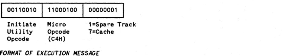
General format of Execute Utility Commands:
... 0_0_'_'
o_o_x_x--'--x-x-x-x-xx-x-x---'----~I
•..
. . . . 1 _ _ _ _ _ _Initiate Utility Opcode