© 2018, IRJET | Impact Factor value: 6.171 | ISO 9001:2008 Certified Journal | Page 278
Design and Development of Three Link Suspension System for a
Quad Bike
Gaurav kadam
1, Mohit Kamble
2, Prajval Vaskar
3, Prathamesh Sangelkar
41,2,3,4
Department of Mechanical Engineering, SAOE, Pune.
---***---Abstract -
In Quad bike, particularly in sports type, Dependent suspension system is used as Rear suspension but there are some drawbacks of the dependent system such as lack of stability, high un-sprung weight, etc. To overcome these drawbacks independent suspension is used (Double wishbone, Three link, Multi-link). Now a-days Double wishbone independent suspension system is widely used in Quad bike because of its ease for manufacturing and cost. But it has some limitations too like it must be incorporated with anti-roll bar to resist rolling which adds the weight to system. So to keep the weight low with high performance suspension and more rolling stiffness three link suspension was designed. The paper describes the design and simulation of this type of suspension in quad bike.Key Words: Independent Suspension, Three Link, CREO 3.0, Lotus Shark, ANSYS 16, Roll gradient.
1. INTRODUCTION
Suspension system is a system which isolates the body and occupants from the irregularities of the road surface. It consists of tire, springs, shock absorbers, linkages. It is important for the suspension to keep the tire in contact with the road surface as much as possible, because all the road or ground forces act on the vehicle through the contact patches of the tires.
Functions of suspension system:
-Provide vertical compliance so the wheel can follow the uneven road, isolating the chassis from irregularities on the road.
-Maintain the wheel in the proper steer and camber attitudes to the road surface.
-React to the control forces produced by the tires-longitudinal (acceleration and braking) forces, lateral (cornering forces), and braking and driving torques.
-Keep the tire in contact with road with, minimal load variations.
- It should transfer minimum forces to the chassis.
-The properties of a suspension system are important to the dynamics of the vehicle primarily seen in the kinematic (motion) behaviour and its response to the forces and moments that it must from tires to the chassis. In addition, the other characteristics considered in the design process are cost, weight, package space, manufacturability, ease of assembly etc.
Dependent suspension system:
This type of suspension system acts as a rigid beam such that any movement of one wheel is transmitted to the other wheel. Also, the force is transmitted from one wheel to the other.
Independent suspension system:
Independent suspension allows each wheel to move vertically without affecting the opposite wheel. Independent suspension provides higher roll stiffness relative to vertical spring stiffness. In this roll center is easy to control by choice of geometry of control arms, the ability to control tread change with jounce and rebound, larger suspension deflections. It also has better resistance to steering vibrations.
1.1 Objective
The objective of this research is design and analysis of independent rear suspension for an all-terrain vehicle (quad bike). In rough terrains suspension plays vital role in ride comfort, load transfers and to some extent in safety too. The suspension was designed keeping all the vehicle performance requirements in these kind of terrains. Three link type of suspension was selected because of its added advantage to rolling stiffness and comparatively low weight.
1.2 Terminology
Degree of freedom:
The assemblage of control arms in suspension system is to control the motion of the wheel in only one path i.e. bumps and droop. That path may also have camber change, castor change and toe change as the wheel moves. So the design of suspension system includes restraining the knuckle to limited motion in five directions.
Instant center of rotation:
It is the point about which the all the links rotates. As in suspension the link moves up and down relative to the road conditions, instant center of rotation plays a vital role in limiting the camber change, castor change etc.
Instant axis:
© 2018, IRJET | Impact Factor value: 6.171 | ISO 9001:2008 Certified Journal | Page 279 Camber gain:
It happens with change in the motion of wheel corresponding to bumps or droops. Length of the links, ICR affects the amount by which camber changes. The more the length of the suspension links less will be the camber change and vice versa. Similarly, the geometry having ICR at long distance have shorter camber gain as the geometry moves in arc having larger radius. Length of the arm also affects scrub of the tire i.e. lateral motion of the tire.
Roll gradient:
The stiffness in roll is conveniently expressed in normalized form as degrees of roll per unit lateral acceleration (deg/g). This is called roll gradient.
2. DESIGN OF THREE LINK SUSPENSION
2.1 Iteration
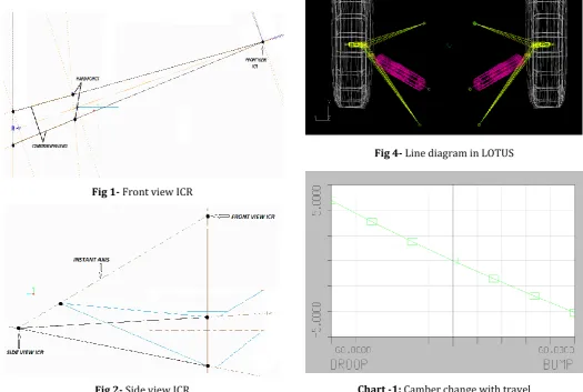
[image:2.595.309.560.54.254.2]The design is based on Instant axis concept.Instant axis was obtained by connecting ICRs in both side view and front view. Various constraints such as chassis, differential, mounting tabs etc. were considered. Iterations were done by changing the position of ICR and the link angles. One with minimum camber change, wheelbase change and track width change was finalized. Knuckle pivot points were assumed considering the packaging of the wheel assembly. Iterations were done using CREO 3.0.
Fig 1- Front view ICR
Fig 2- Side view ICR
Fig 3- Top view ICR
2.2 Simulation
[image:2.595.308.561.385.531.2]The suspension simulation was done in LOTUS SHARK. The position of the hard points was imported from the link design in CREO. It gave various dynamic parameters of the suspension system, summary of which is illustrated via images below.
Fig 4- Line diagram in LOTUS
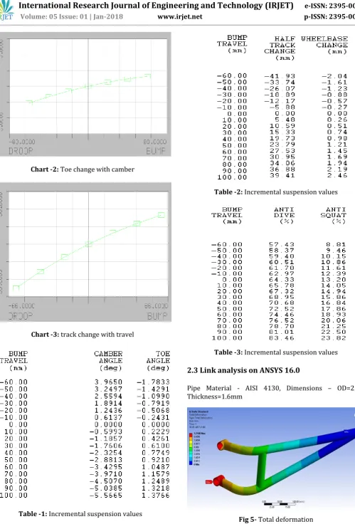
[image:2.595.33.559.410.763.2]© 2018, IRJET | Impact Factor value: 6.171 | ISO 9001:2008 Certified Journal | Page 280 Chart -2: Toe change with camber
[image:3.595.45.545.36.773.2]Chart -3: track change with travel
Table -1: Incremental suspension values
Table -2: Incremental suspension values
Table -3: Incremental suspension values
2.3 Link analysis on ANSYS 16.0
[image:3.595.35.287.292.490.2]Pipe Material - AISI 4130, Dimensions – OD=25.4, Thickness=1.6mm
[image:3.595.339.534.323.518.2]© 2018, IRJET | Impact Factor value: 6.171 | ISO 9001:2008 Certified Journal | Page 281 Fig 6- Von misses stress
Sr. No Parameters Values Obtained
1 Maximum deformation 7.21mm 2 Equivalent stresses 398Mpa
Table -4: Result
2.4 Calculations for Ride rate and Roll rate
Front Track width (tf) = 3.5 feet
Rear Track width (tr) = 3.33 feet
Wheelbase (l) = 3.83 feet
Height of C.G from the ground (h) = 1.44 feet
Distance between C.G to Roll axis (H) = 0.8 feet
Cornering radius (R) = 10 feet
Speed of vehicle (V) = 15 Km/h
Angle of banking (α) = 0°
Weight on front left tire (W1) = 100 lb
Weight on front right tire (W2) = 100 lb
Weight on rear left tire (W3) = 122.22 lb
Weight on rear right tire (W4) = 122.22 lb
Total weight on Front tires (Wf) = 200 lb
Total weight on rear tires (Wr) = 244.44 lb
Total Weight of vehicle (Wt) = 444.44 lb
Calculation for location of C.G
Location of C.G from rear axle (b) = (Wf * l)/Wt
= (200*3.83)/444.44
= 1.723 feet
Location of C.G from front axle (a) = l-b
= 3.83-1.723
= 2.107 feet
Lateral acceleration = V2/Rg
=192.51/ (10*32.2)
=0.59 g’s
As there is no banking of road
Effective weight (W’) = Total weight (Wt)
Therefore, Effective weight on front side= Total weight on front side
(Wf’) = (Wf)
= 200 lb
Effective weight on rear side= Total weight on rear side
(Wr’) = (Wr)
= 244.44 lb
Weight transfer due to lateral acceleration
Assume the vehicle is taking right turn
Weight transfer on front axle = (lateral acceleration *height of C.G.* front axle load)/front track width
= 0.59*1.44*200/3.5
= 49.19 lb
WFO= 100+49.49
= 149.49 lb
WFI= 100-49.49
= 50.51 lb
Weight transfer on rear axle = (lateral acceleration *height of C.G.* front axle load)/ rear track width
= 0.59*1.44*244.44/3.33
= 62.36 lb
WRO = 122.22+62.36
= 184.58 lb
WRI= 122.22-62.36
© 2018, IRJET | Impact Factor value: 6.171 | ISO 9001:2008 Certified Journal | Page 282 Change from the static level measured on the ground
WFO = 149.49-100=49.49 lb
WFI = 50.51-100 = -49.49 lb
WRO = 184.59-122.22= 62.36 lb
WRI = 59.86-122.22= -62.36 lb
Assume 3.5 inches of jounce travel and use 2.5 inches to accommodate weight increase allowing 1 inch for additional travel due to braking, acceleration and localized bump on the track.
Ride rates
Ride rate front (KRF) = 49.49/2.5 = 19.79 lb/inch
Ride rate rear (KRR) = 62.36/2.5
= 24.94 lb/inch
Ride frequencies assuming side to side geometry
ωF = 1/2π (KRF * 12 *32.2/W1)
=1/2π (19.79 * 12 *32.2/100)
= 1.39 Hz or 83.88 cpm
ωR = 1/2π (KRR * 12 *32.2/W3)
= 1/2π (24.94 * 12 *32.2/122.22)
= 1.41 Hz or 84.79 cpm
Most rear drive vehicle, the front natural frequency is higher than rear, based on front roll stiffness requirements. At this point, ωR cannot be less than 84.79 cpm without using up the 2.5 inch of bump travel. This cannot be decreased, thus ωF will be increased to 115 cpm.
To increase ωF square the ratio of natural frequencies.
ωFnew / ωFold = ( 115/88.88)2
= 1.87
Therefore new front ride rate is = 19.79*1.87 = 37.19 lb/inch
Assuming left and right ride rates are same Therefore roll rates,
KΦF =12*KRF* tf2 /2
= 2733.46 lb-ft/rad.
KΦR = 12* KRR* tR2 /2
= 1659.34 lb-ft/rad.
Roll gradient = Φ/lateral acceleration= -W*H/ (KΦF + KΦR )
= -444.44*0.8/(2733.46+1659.34)
= - 0.08 rad/g or -4.63 deg/g.
[image:5.595.307.560.192.333.2]3. VEHICLE PHOTOS
Fig 7- Three link suspension on quad bike
Fig 8- Vehicle during cornering
4. CONCLUSION
After numerous iterations on link design, we were able to formulate and implement a three link suspension for a quad bike. Suspension had a little more camber gain compared to double wishbone but it successfully fulfilled the requirement of less vehicle roll. As an all-terrain vehicle it had sufficient wheel travel with more vehicle stability and durability.
REFERENCES
[1] William F. Milliken and Douglas L. Milliken, “Race Car Vehicle Dynamics”; ISBN 1-56091-526-9.
[2] Carroll Smith, “Tune to Win”.
[3] Thomas D Gillespie, “Fundamentals Of Vehicle Dynamics”.
[image:5.595.308.559.369.506.2]