© 2018, IRJET | Impact Factor value: 6.171 | ISO 9001:2008 Certified Journal | Page 3625
Automated Loop Winding Machine for Steering Coupling
Pranish Naoghare
1, Aquib Khatib
2, Zuber Pathan
3, Atul More
41,2,3,4
Student,Dept. of Mechanical Engineering, Guru Gobind Singh College of Engineering & Research Centre,
Nashik, Maharashtra, India
---***---Abstract -
Manufacturing is the production of commodities
for use or for sale using labor and machines, tools, chemical and biological processing, or formulation. Manufacturing engineering or processes are the steps through which raw materials are transformed into a final product. Manufacturing automation is an important tool in large scale production, especially to be competitive on a global market and to create and keep new industries in developing countries. Within manufacturing automation, Industrial robots are rapidly growing in numbers. Less expensive robots with higher performance, easier programming and improved offline simulation software, together with smaller product series, enable automation of complex tasks. This paper focuses on design and development of an automated loop winding machine to replace the manual loop winding process particularly done in manufacturing of steering couplings in automobiles. Automated loop winding machine will help overcome many human limitations, reduce time consumption, improve accuracy, thereby increasing productivity.
Key Words: Steering Coupling, Loop Winding,
Manufacturing Automation, Automated Loop Winding Machine
1. INTRODUCTION
Manufacturing engineering or manufacturing process are the steps through which raw materials are transformed into a final product. The manufacturing process begins with the product design, and materials specification from which the product is made. These materials are then modified through manufacturing processes to become the required part.[1] Manufacturing systems consist of human workers, automation, and various material handling technologies, configured in ways that create specific manufacturing system typologies. More specifically, a manufacturing system is a collection of integrated equipment and human resources, whose function is to perform one or more processing and/or assembly operations on a starting raw material, part, or set of parts.[2]
2. MANUFACTURING SYSTEMS
The manufacturing system is where value-added work is performed to parts and/or products, and this activity gives manufacturing a central place in the overall scheme of the system of production, where it is supported by systems of manufacturing support, quality control, material handling, and automation control. Different types of manufacturing systems may be identified as follows:
i. Single station ii. Machine cluster iii. Manual assembly line iv. Automated transfer line v. Automated assembly systems vi. Machine cell
vii. Flexible manufacturing systems (FMS)[2]
Most manufacturing in modern-day manufacturing systems is done by machines of one form or another. Machines can be classified according to worker participation in the task, as:
i. Manual operated machines: Controlled or supervised entirely by the worker. The worker must attend the machine continuously during the work cycle.
ii. Semi-automated machines: This performs a portion of the work cycle under programme control, and then a worker assumes control for the remainder of the cycle. The worker must attend the machine every cycle, but need not be continuously present.
iii. Fully automated machines: This has the capability to operate with no human attention for period of time that is longer than one work cycle.
3. LOOP WINDING IN STEERING COUPLING
A steering coupling, also commonly referred to as a steering damper, is a steering system component that is commonly found on many vehicles. It is a rubber disc that is designed to absorb and dampen vibrations. As a vehicle is driven, vibrations from contact with the ground are transferred through the vehicle’s steering system, up to the steering wheel. It is the job of the steering coupling to absorb these vibrations, which could otherwise cause driver fatigue, and even steering issues. When the steering coupling fails, it can have negative effect on the vehicle’s handling capability, as well as make driving the vehicle uncomfortable.
These steering couplings consist of loop windings in them. These loops are made of polyester wire, wound in a particular pattern. These windings are provided for the following reason:
© 2018, IRJET | Impact Factor value: 6.171 | ISO 9001:2008 Certified Journal | Page 3626
4. LITERATURE SURVEY
A. Gonzalez-Rodriguez, (2017) et.al. proposed a new design solution to connect the fixed frame to the end-effector in cable-driven robots. The conventional point-to-point model to describe the kinematic and dynamic behaviour of cable robots has been recall for both planar and spatial cables robots. This usual way of modelling assumes that no pulleys are placed at the fixed frame, but the radius is only taken into account to compute cables lengths variations when drums roll in or out them. Indeed, it is shown in this paper that important inherent errors appears when this simplification is made due to the difference between the lengths and orientations of the cables in the model and the real system, which in turn originate deviations in the robot Kinematics and Dynamics. In order to overcome the mentioned problems, we propose a novel design solution that includes pulleys at the end-effector, with the same radius as the fixed pulleys or winches at the frame. This solution makes the cable lengths and orientations equivalent to those of the point-to-point model. In addition, the static Jacobian matrix is also analytically equivalent to the point-to-point model which can then be used to describe the system dynamic behaviour without the mentioned errors.[3]
D. Saravanakumar, (2017) et. al. presents an extensive study on various developments in the positioning control of the pneumatic cylinders. The pneumatic actuators offer numerous advantages such as cleanliness, low cost, high power to weight ratio, easy maintenance, safety, anti-explosive, long working life. But the accuracy of the actuator is affected badly by its nonlinear characteristics. The nonlinear characteristics such as nonlinear frictional forces, the thermodynamics of the air pressure in the chambers of the cylinder, time varying load, nonlinear valve characteristics makes the servo pneumatic system more uncertain. An extensive survey of literatures on history, applications, characteristics, component selection, modelling and accurate control of the servo pneumatic system is presented in the paper. The highly nonlinear and uncertain system attracted more control engineers to work in this field. The paper also presents the additional measures taken to improve the energy efficiency and positioning accuracy of the pneumatic system. The literatures present the positioning accuracy of the pneumatic cylinder upto micrometre level. The hybrid systems with combined pneumatic and piezoelectric actuators report an accuracy upto 10 nm for operational range upto300 mm.[4]
Sergey Edward Lyshevski, (2017) This paper examines nonlinear mechatronic systems with direct-drive limited-angle axial-topology actu- ators. The considered direct-drive servos are used in hard disk drives, manipulators, pointing systems, robots, rotating platforms, aerial vehicles, etc. High accuracy, precision and fast repositioning should be ensured despite friction and adverse phenomena which degrade overall performance and capabilities. Tracking control laws which compensate friction using the estimated parameters are designed. The ad- verse friction is compensated by a
nonlinear feedback. Adaptive reconfiguration is ensured by estimating the unknown parameters in near real-time. Design and technological challenges are overcome by a con- sistent paradigm and hardware-centric concurrent design. The concept and solutions are experimentally verified.[5]
Yanbing Tian,(2013) et. al. presents a design which involves the combination of pneumatic servo system and electric servo system. Precision servo system is important part in the ultra-precision machining; it is an indicator for a country's ultra-precision technology level. Now most of precision servo positioning system is using electric motor to drive, there is a large space needed; slow response and other shortcomings, so the motor drive is limited in the precision control. The accuracy of the domestic ultra-precision positioning servo system is not high, and the displacement is short. A coarse and fine control air suspension processing stage is designed in this paper. Metal bellows and the voice coil motor are used as the driving element, aerostatic stage is used to support the working stage, and the control accuracy of the motion stage is improved under conditions without friction.[6]
5. PROJECT DETAILS
5.1 Company Background
INNOVA RUBBERS PVT. LTD. is located at Ambad, Nashik, Maharashtra. The industry is one of the technological leader in designing and manufacturing of automotive and industrial rubber moulded and rubber to metal bonded anti-vibration parts. The industry produces silent block bushes, engine mounts and transmission mounts, propeller shaft mountings, torsional vibrational dampers, bare rubber parts, control arms, etc.[7]
5.2 Problem statement
After studying the entire process of loop winding for steering coupling, the problem statement can be stated in following points:
i. Number of operations are carried out at different stations. This results in increased cycle time, making the process time consuming.
ii. As the time required is more the rate of production is low, thus affecting the productivity of the process. iii. There is no control over the pattern of winding,
causing uneven winding.
iv. Due to involvement of man, the tension on the wire varies during the entire winding operation. v. To maintain proper winding and tension in the wire
skilled operators are required.
vi. As the process involves number of stations, man power required is more.
© 2018, IRJET | Impact Factor value: 6.171 | ISO 9001:2008 Certified Journal | Page 3627
5.3 Objectives
Following are the objectives that were focused upon during the course of the project:
i. To reduce the time required for the entire process. ii. To increase overall productivity.
iii. To eliminate human limitations. iv. To reduce the labor force required
v. To combine multiple operations. vi. To reduce wear of wire.
[image:3.595.304.561.78.185.2]5.4 Project model
Fig -1: 3D Project Model Components in this project are:
i. Robotic Arm ii. Oven
iii. Chemlock Container
iv. Thread stand by arrangement v. Fixture
vi. Thread Feeder
vii. Guide pulleys on supports
Fig -2: 2D Project Model (Front View)
[image:3.595.335.549.235.481.2]Fig -3: 2D Project Model (Top View) 5.5 Project Working
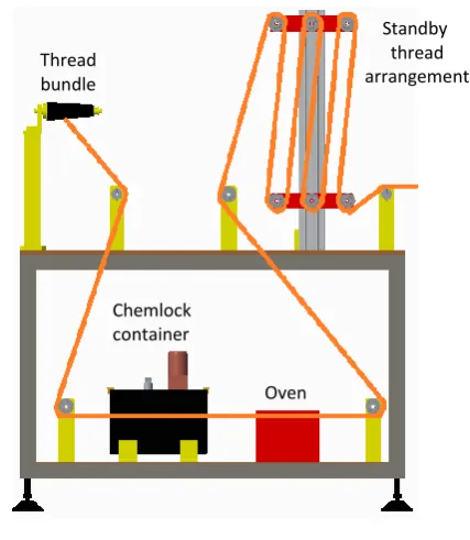
Fig -4: Thread Path
The above figure shows the travel of thread during the working cycle. The thread is unwound from the bundle. It is passed through a chemlock container with the help of couple of pulleys. This chemlock is an adhesive liquid which is to be coated over the thread so that during the moulding with rubber, the rubber and the thread loops form a strong bond with each other. After passing through the chemlock the thread is further dried in the oven. The thread is then passed over a standby thread arrangement using couple of pulleys. This arrangement is so provided to ensure that chemlock is applied over the thread and also to keep thread ready for winding. This thread is further passed to the robotic arm(Make: Omron- YK600XGL-150). The robotic arm is programmed to perform loop winding over the pins placed in the fixture.
Chemlock container
Oven Thread
bundle
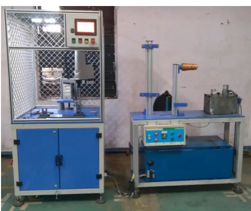
[image:3.595.35.287.259.439.2]© 2018, IRJET | Impact Factor value: 6.171 | ISO 9001:2008 Certified Journal | Page 3628 Fig -5: Project Setup
6. RESULTS AND DISCUSSION
After completion of project trails were taken on the machine. Trails were not giving satisfactory results initially. Some of the reasons for this were:
i. Improper fittings of the pulleys
ii. Slippage of thread from the grooves of the pulley. iii. Sudden jerks to the movement of thread.
iv. Breaking of thread.
But over the time these problems were overcomed by: i. Properly aligning the pulleys.
ii. Providing lubrication to pulleys iii. Reducing the tension on thread iv. Replacing of faulty pulleys.
The loop windings were then sent for transfer moulding. The steering couplings obtained from the mould were sent for testing for their stiffness.
The stiffness results obtained were as follows:
Table -1: Results table
Sr no. Cavity no.
Torsional stiffness (6~9 N.m/deg)
Axial stiffness (52~78 N/mm)
1 1 7.24 60.66
2 2 7.63 58.62
3 3 8.35 60.69
4 4 6.83 62.23
5 5 7.71 53.97
6 6 6.96 59.71
Since all the outcomes of the test are within the specified value, all the steering couplings are accepted.
7. CONCLUSION
Today’s fast and flexible robots work in industries ranging from rubber and plastic processing to semiconductor manufacturing and research. While still a mainstay of high-volume production, robots are finding more roles in small to medium-sized operations.
With the implementation of the project:
i. The time required for total loop winding process was reduced to 3 minutes.
ii. Numbers of processes are combined together. iii. Material handling of the units is reduced to
minimum.
iv. Idle time is eliminated.
v. Labor requirement and constraints are reduced.
REFERENCES
[1] https://en.wikipedia.org/wiki/Manufacturing
[2] “Cellular Manufacturing: Mitigating Risk and Uncertainty”, John X. Wang, CRC Press
[3] A.Gonzalez-Rodriguez, F.J.Castillo-Garcia, E.Ottaviano, P.Rea, A.G.Gonzalez-Rodriguez, “On the effects of the design of cable-Driven robots on kinematics and dynamics models accuracy”, Proceedings of ELSEVIER presents MECHATRONICS 43 (2017), pp.18-27.
[4] D.Saravanakumar, B.Mohan, T.Muthuramalingam, “A review on recent research trends in servo pneumatic positioning systems”, Proceedings of ELSEVIER presents Precision Engineering 49 (2017), pp.481-492.
[5] Sergey Edward Lyshevski, “Control of high-precision direct-drive mechatronics servos: Tracking control with adaptive friction estimation and compensation”, Proceedings of ELSEVIER presents MECHATRONICS 43 (2017), pp.1-5.
[6] Yanbing Tian, Tao Wang, Meiling Wang, “Modeling of Ultra-precision Pneumatic Servo Control Stage”, Proceedings of 6th IFAC Symposium on Mechatronic Systems The International Federation of Automobile Control, April 10-12, 2013, pp.453-456.
© 2018, IRJET | Impact Factor value: 6.171 | ISO 9001:2008 Certified Journal | Page 3629
BIOGRAPHIES
Pranish Naoghare
Student, Bachelor of Engineering (Savitribai Phule Pune University) Guru Gobind Singh College of Engineering & Research Centre, Nashik
Aquib Khatib
Student, Bachelor of Engineering (Savitribai Phule Pune University) Guru Gobind Singh College of Engineering & Research Centre, Nashik
Zuber Pathan
Student, Bachelor of Engineering (Savitribai Phule Pune University) Guru Gobind Singh College of Engineering & Research Centre, Nashik
Atul More