RELIABILITY AND INFORMATION SHARING SECURE
TRACE-OUT PROTOCOL IN ROUTER BASED NETWORKS
1M HEMA LATHA, 2P PADMANABHAM, 3A.GOVARDHAN
1Asst.Prof, Lakireddy Balireddy College of Engineering (LBRCE)
Mylavaram, Krishna District, A.P., INDIA
2Professor Department of CSE & Director of Academics
Bharat Institute of Engineering and Technology. Hyderabad. A.P. INDIA
3Professor, Department of CSE & Director of Evaluation JNTUH, Hyderabad, INDIA
E-mail: [email protected]
ABSTRACT
Dependency upon Communication adaptability to a wide range and digitalization of network adds a number of devices in the network. These devices operate throughout every corner of the world as well as different purposes. Huge data transmission, easy to access and time saving are the applications that are attracting the users to have a digitized communication system. Wireless communication systems consist of a number of routers and links. Processing speed, link failure, control of one router over another router as well extended delay causing huge problems in transmission. Considering some of the physical data available and sharing the useful information to the other routers as well as maintaining a suitable protocol to detect the type of failure gives the work culture of this paper. This paper enhances the methodology through less use of bandwidth for error or attack checking. The error is detected as soon as possible on the network. The work load of error checking is distributed among a number of devices.
Keywords:- Information, Bandwidth, Trace, Routers, Error
1. INTRODUCTION
The world is connected through multiple data sharing centers. Long range and variation in operating regions imposes requirement of routers in networks. Routers are coming pressures like the failure of hardware [1], unwanted control of another node over it [2], losing of data or changing of data present in the data packet [3] [4] [5] or headers, used for data carrying. As the distance between the source and destination and the region of local area network (LAN) are increasing respective quantity, the risk of network failure is going on increasing [4]. Dependencies of multiple important factors on the networks are growing exponentially in day to day life. This leads to the discovery of a suitable protocol, which is able to detect and replace data packet transmission paths. Introduction of long range transmission through a number of routers widens the area of interest in wireless networks. Although repeater and router in the network solving the coverage problem, it is enhancing the causes of errors. Some of the most common errors include flow of the data in a way [6] [7], which are not coming under the routing protocols. Few unwanted nodes having some adverse effect on the networking system [8]. They try to alternate the
flow of data. Cryptographic data for data transmission is one of the solutions present in network [9] [10]. Some solution present in the network focuses acknowledgement based transmission technique [3]. This technique is able to solve basic problems of the network. Still generation and transmission of acknowledgement put pressure on security threats detection method and on the transmission system. The reliability is decreasing as many as transmission occurs. Protocols are unable to detect errors as soon as possible.
1.1 Architecture
such criteria as storage overhead either within the packet itself or at the nodes traversed, link speeds, or computational demands, among other mitigating factors; each category has its advantages and disadvantages. For example, the hash-based approach [13] is a logging method that can trace a single packet, unlike most packets marking schemes, which assume a reasonably large number of packets for a successful trace back. Another routing technology Stealth probing is a secure data plane monitoring tool that relies on the efficient symmetric cryptographic protection of the IPsec protocol suite that is applied in end-router-to-end-router fashion. One of the other protocol present is BGPmon, which is designed to scalable monitor BGP updates and routing tables from many BGP routers simultaneously, while providing a consolidated user-friendly inter- face. BGPmon uses XML to represent BGP messages, handling all attribute and element types, and various classes of data [14].
1.2 Applications
Cryptographic protocols are small programs designed to ensure secure communications over an un trusted network. Their security is of crucial importance due to their widespread use in critical systems and in day-to-day life [15]. Large open networks, where trusted and un trusted parties coexist and here messages transit through potentially “curious” if not hostile providers pose new advantages to the designers of communication protocols [16]. Network routers occupy a key role in modern data transport [17]. Modern ISP, enterprise, and data center networks demand reliable data delivery to support performance-critical services, thus requiring the data plane to correctly forward packets along the routing paths. Real-world incidents reveal the existence of compromised routers in the ISP and enterprise networks that sabotage network data delivery [18]. Network Scanner or Network Enumeration is a computer program used to retrieve user names, and info on groups, shares and services of networked computers [19].
1.3 Issues
It is important to initially emphasize that erasure security be relative [20]. Attacks that are hinged upon the guess-ability of initial TCP sequence numbers (ISN): so that an arbitrary host can exploit an address-based trust relationship to establish a client writes-only TCP session [21]. Securing IP routing is a task that is central in diminishing the Internet's liability to mascon gyrations and malicious attacks [22]. As there are numerous
attacks on published protocols, designing AKE protocols is error prone. It is therefore desirable to formally verify them before deployment, ideally automatically and with respect to an unbounded number of sessions [23]. In large and constantly evolving networks, it is difficult to determine how the network is actually laid out. This information is invaluable for network management, simulation, and server siting [24]. Traditional topology discovery algorithms are based on SNMP, which is not universally deployed [25]. Compromised routers can drop, modify, mis-forward or reorder valid packets [26]. The predominant inter-domain routing protocol in the Internet, BGP, includes no mechanism for verifying either the authenticity (correct origin) or the accuracy of the routing information it distributes. Traffic can be severely disrupted by routers refusing to serve their advertised routes, announcing nonexistent routes, or simply failing to withdraw failed routes, as a result of either malfunction or malice. A particularly problematic case is that of sophisticated malicious routers (e.g., routers that have been compared) [27].
Acknowledgement base attack and error detection is a suitable process. But the disadvantages come when just bandwidth used is wasted upon acknowledgements. Some algorithms present like ant colony is inefficient. So this paper
proposes information sharing and
acknowledgement on error detection method to trace out the attack and error as soon as possible.
To provide a solution this paper first gives an introduction that is best suitable for this paper. Then the paper proceeds to some literature review that is present in section two and produces a view of some other author. The literature view is followed by a suitable proposed method that includes details of problem definition and solution with clearer information about the proposal. Then the overall concept and advantages with future work is described as conclusion at the end of the paper.
2. LITERATURE REVIEW
This approach complements efforts that focus on securing the routing protocol itself. The authors view secure trace route as a general technique with wide applicability, and are investigating it in the context of multi-hop wireless networks.
The authors of [28] say FD protocols require only pairwise participation of nodes, deployment of FD can proceed in an incremental fashion that is compatible with incentives for informing routing decisions at the network edge. However, when the authors consider the placement and selection of FD protocols, natural questions arise about the division of labor between the end host and the edge router. They argue that the placement of FD protocols depends on the parties responsible for providing confidentiality and driving routing decisions.
Pepper and Salt Probing may even be efficient enough to be deployed in the core of the Internet, as part of an architecture where core routers inform their routing decisions by running FD to destination networks.
The authors of [29] have designed and analyzed efficient path-quality monitoring protocols that give accurate estimates of path quality in a challenging environment where adversaries may drop, delay, modify, or inject packets. Their protocols have reasonable overhead, even when compared to previous solutions designed for the non-adversarial settings. To monitor path quality in a manner that is robust to non-adversarial failures such as congestion, mis-configuration, and malfunctions. Then, the same router support could be leveraged, using secret keys, to operate in an adversarial setting as needed.
Accurate techniques for determining when performance degrades beyond a threshold will offer significant improvements for edge networks balancing load over multiple paths through the Internet. In addition, we are exploring how to compose multiple instances of our PQM protocols running over multiple paths simultaneously to determine whether the adversary resides on either the forward or reverse path, or to localize the adversary to particular nodes or links.
3. PROBLEM AND PROPOSED SOLUTION
3.1 Problem Definition
Previous papers [2] [3] are trying to solve the problem by giving an efficient routing technology or acknowledgement based error detection for errors and attack detection. Only routing is unable to solve the problem of data transmission efficiently. Whenever an error is detected through
acknowledgement for every data packet, it is leading to the acknowledgement overhead in the network and errors in acknowledgement transmission. Some other authors have also tried to give the solution making the calculation at the receiver node only. If there is any failure in the receiving node, the whole error detection technique will spoil. Errors cannot be detected as soon as possible in the methods given in the previous paper. The methods described by some authors which describe the error detection through sending data packet to multiple routers and comparing the response from them are leading to huge work load and use of valuable bandwidth.
3.2 Proposed Methodology
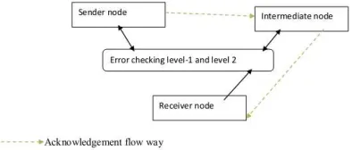
This method considers a network that consists of a number of nodes and number of end user devices. The end user devices communicate with each other through the routers. This paper focuses on local area network devices and its issues. The whole paper is described based on local area networks (LAN). The architecture of LAN technologies is given below.
Generally the data packet is sent from the source (s) to the destination (D) through a number of routers (R). Every data packet is having a data packet number that is alpha numeric in nature (DN). Every node (sender, router, and receiver) in the network is having their unique address ID (Uid).
The data packet carries like total numbers of data packets to be sent, timer, maximum delay, and intermediate router fields. Here maximum delay (Md) is previously determined by the experts in the
ability to take decision of further processing of data packet. Every node can generate the data packet and transmit it to other nodes (router and end nodes) present in the network. They are able to send the acknowledgement to the other nodes. All the nodes are taking part in two way communication.
Figure: 2 Showing Architectural Diagram
3.2.1 Data packet Generation
It is proposed to make a character array for producing a unique number for every data packet. Every node has a node ID having X alphanumeric characters. The number of the data packet is also an alpha numeric. Suppose it is of N characters. The nodes, which are also the part of the network, are having X alphanumeric characters in it. Here the values of X and N was determined at the time of
initialization of the network. The size (value) of X depends upon the number of the nodes present in the network. The value of N depends upon the amount of data packet is required to send. Suppose X1 is the last node traveled nodes ID.
When a sender wants to send some data packet to a destination, it generates the data packet in the structure below. The data packet carries the data packet number, destination node's address, the maximum delay (Md), the current time of the sender
(Sct), intermediate routers’ identity and number of
data packets to be sent to the specific node. As mentioned above the data packet number is carrying the information about the sender node, it is easy to extract the sender’s unique identity number (Uid) at the intermediate and receiver nodes.
Receiver field carries destination address. Here maximum (Md) delay is prefixed and decided at the
sender node. Current time (Sct) is the time when the
[image:4.612.97.520.415.449.2]sender generates the data packet. Number of data packet is a numeric number that is the approximate number of data packet to be sent to the specific destination.
Table: 1 Data Structure Flow From Sender To Destination
Here intermediate router identity has been present just to find the errors and attacks in router and link level.
The second type of data packet is an acknowledgement data packet. This packet carries a
sender’s identity, receiver’s identity, intermediate router's identity, current time, the last un-corrupted data packet number. A structure of the data packet is given below.
Table: 2 Acknowledgement Packet Structure From The Destination Or Router Node
Here the status field is a flag field. If the status is set to 0, then it is treated as smooth transmission. If the status is one, then the status is problematic. The detection of the problem is given in the last section of the proposed method. If the status is one then the only problem type field will be filled.
3.2.2 Levels of Checking
The error checking method presents at router nodes and receiver nodes-
Table: 3 Level 1 Authentication Of Data Packets For Error Detection
Data packet number
Extracted node number
Authentication nodes
Status
AXN X Set {nodes} Accepted/rejected
node's identity is processed for matching through a number nodes identity present at the intermediate nodes and destination nodes. Then the status field is updated that decides whether to process the data packet to the next stage or not. If the status is accepted which is because of a valuable matching present, then the data packet is processed to the next error detection field.
For the level two error checking this method derives a number of formulas given below.
There is one flow factor (FF) is designed. Here the flow factor is the ratio of data packets per unit time. The controller present at the router and the destination node calculates the flow factor. Mathematically it is given as
. ) 1 ( ... ... ... ... ... time unit Ut packets data of number whereNdp Ut Ndp FF = = =
A receiver and intermediate node (routers) calculate number factor (DPnf) of data packet. The
number factor is given by the flow factor multiplied by the time difference of two nodes (sender node and current node) divided by unit time. Mathematically it can be written as –
. , , , ) 2 ...( ... ... ... ... unittime Ut node sender the of time current Sct node receiver the of time current Rct flowfacto whereFF Ut Sct Rct FF DPnf = = = = − ∗ = T
Here are a few claims supporting our proposed method as given below.
Claim-1: The current time (Rct) at the router or
destination is less than the sum of sender’s current time (Sct) and maximum delay (Md) {Rct<(Sct+Md)}
then receiver or intermediate node generates an error or attack message in the network.
Claim-2: The value of the number of data
packets (DPnf) should be in between s. Tdp and s1.
Ndp. Presenting through mathematic it can be
written as s.Tdp <DPnf <s1.Ndp .
Here s and s1 are two standard values. Value of s always remains between 0 and 1 and have to be determined by the experts at the time of design of network, which is also called reliability factor. The factor is called a lower bound reliability factor. The value of s1 can be more than one. It is called upper bound of reliability factor. The upper limit of reliability factor is also decided by the experts before the initialization of the network. These factors depend upon the efficiency required for the network
The importance of reliability factor is more in the network as it finds the attacks as well as errors present in the network transmission.
The second step is finding failure as soon as possible while data transmission. In this step data extracted from the data packet are arranged in a data table.
Table: 4 Level Two Authentications Checking In Receiver And Intermediate Node Data packet
number
Sender’s identity Maximum delay (Md)
(in seconds)
Receiver’s current
time (Rct)
Sender’s current
time (Sct)
Status
AXN X Md …………. ……….. Accepted/
Rejected
The table two is filled with the information got from the data packet itself. The table includes fields of data packet number, sender’s identity, maximum delay, receiver’s current time, sender’s current time and status. The status is set by the node through following the protocol one.
After successfully crossing the checking at level-2, the data packet is processed to third level checking. At this level, the information extracted from the data packet is stored in another table. The data table count and extracts some advanced value from the received data. It is updated timly and compared. The structure of table is given below-
Table: 5 Level Three Authentications Checking At Receiver And Intermediate Node Data packet
number
Sender’s identity
Number of data packets
to be sent (Tdp) (no unit)
Flow factor (FF) (no unit)
Number factor (no unit)
Status
AXN N ……… ……… ……….. Accepted/rejected
At this level the status is set by following the protocol two. In the above table the field of number of data packets to be sent is carrying only numeric
3.2.3 Detecting Attacks or Errors
If the status is rejected then the data packet is precede to finding the exact errors present in it. The problems are found out from the below combinations and criteria.
1. If the DPnf value is less than s.Tdf , then the error
is detected as link or router failure. The type of problem is added in the acknowledgement packet. The failure can treated as hardware failure.
2. If the DPnf value is more than s1.Ndp then
transmission is detected as attacked by some malicious node. Some node has tried attack on routers and links present in the network. This indicates bandwidth is used for un-favorable purposes.
As the problem is identified as soon as it occurred, so the attack or error should be checked at previous node or link only.
3.2.4 Attack or Error Avoidance
To avoid such kind of problem as mentioned in section 3.2.2 and 3.3.3, this paper proposes below procedure.
Step-1 – If any problem detected, the node (Xi),
which detect the problem sends an acknowledgement to the previous node or router. The previous node’s (Xi-1) identity can be extracted
from the intermediate field of the data packet. Step-2- After getting an error indicated acknowledgement packet, a node or router (Xi-1)
has to send it to the previous router or node (Xi-2).
This can be detected from the acknowledgement packet.
Step-3 – The node (Xi-2) try to connect the problem
detecting node (Xi) through the other router except
the previous middle router (Xi-1). The data packets
having the number from the last un-corrupted data packet number have to be processed or transmitted again.
This procedure will continue till successful transmission.
3.3 Overall Procedure
• When a sender node wants to send a stream of data packets, it has to send the data packets continuously or in a streamed manner.
• The details data packet is given in section 3.2.1. In this section it is shown how the intermediate nodes send the data packets to the next router adding its address field in the intermediate field.
• This method detects attack or error signals in an inverse way. This method focuses on the relation between fixed target and achieved target till current situation instead of calculating the relation between progress with the beginning of the process. This
technique presented in this paper avoids more traffic injection and computing overload caused by an extra amount of data transmission and more data transmission due to acknowledgement based service.
• When a router or destination is getting a data packet, it goes for three levels of checking. That is given in section 3.2.2 . The routers and the destination are keeping data tables for errors or attack detection.
• The receiver (which is a router or destination) generates acknowledgement for the first receive of a specific data packet from a specific sender. The detail about the acknowledgement data packet is given in section 3.2.1.
• Few protocols have been designed in section 3.2. 2.
• Arithmetic calculation is being done in section 3.2. 2 to support this paper’s problem detection technique.
• If an intermediate node or router found, the above found conditions are not fulfilled the receiver nodes are able to generate an error or attack signing data packet in the network. This is clearly given in section 3.2.1.
• Acknowledgement packets only to be sent from receiver at first receiving of the data packet, at error or attack signal generation and completion of the data transmission towards the sender. According to the requirements of the reliability of network, acknowledgements can be sent at predetermined interval of time. To avoid the huge errors in data transmission where the size of the set of data packets to be transmitted is very big, this method proposes acknowledgement should be sent at regular interval of time.
• After detecting the problem in the network, the data packet is subjected to find the exact problem. The detail of finding problem is given in section 3.2.3
• The problem is solved according the solution given in section 3.2.4 .
4. PERFORMANCE EVALUATION
4.1 Simulation Setup
proposed Reliability and Information Sharing Secure Trace-out (RISST) protocol with a normal network scenario in which attacks and failures are not detected. The simulation settings are given in the following table.
Table: 6 Simulation Settings
Nodes 60
Link bandwidth 3-7 Mb
Link Delay 10ms
Traffic Exponential / Poisson
Packet size 500 bytes
Rate 5.1 to 5.5 Mb
Simulation time 50 seconds
4.1 Results
We vary the attack traffic rate from 1Mb to 5Mb.
Rate Vs Throughput
1.3 1.35 1.4 1.45 1.5 1.55
5.1 5.2 5.3 5.4 5.5
Rate (Mb)
M
b
/s RISST
Normal
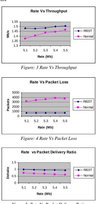
Figure: 3 Rate Vs Throughput
Rate Vs Packet Loss
0 1000 2000 3000 4000 5000
5.1 5.2 5.3 5.4 5.5
Rate (Mb)
P
a
c
k
e
ts RISST
Normal
Figure: 4 Rate Vs Packet Loss
Rate vs Packet Delivery Ratio
0 0.5 1 1.5
5.1 5.2 5.3 5.4 5.5
Rate (Mb)
D
e
lr
a
ti
o
RISST
[image:7.612.97.293.158.237.2]Normal
Figure 5. Rate Vs Packet Delivery Ratio
Rate vs Misdetection Ratio
0.038 0.04 0.042 0.044 0.046
5.1 5.2 5.3 5.4 5.5
Rate (Mb)
M
is
d
e
te
c
t
RISST
Figure: 6 Rate Vs Misdetection Ratio
Rate vs Falsepositive
0 0.0002 0.0004 0.0006 0.0008
5.1 5.2 5.3 5.4 5.5
Rate (Mb)
F
a
ls
e
p
o
s
it
iv
e
RISST
Figure: 7 Rate Vs False Positive
Figure 3 presents the results of throughput in terms of Mb/s. The increase in rate, results in more traffic and hence the received throughput also increases. But RISST attains more throughput when compared to normal scenario.
Figure 4 and 5 shows the packet loss and packet delivery ratio, respectively. The packet loss linearly increases for the normal scenario whereas it is steady and constant in RISST as per figure 4. Because of the effective detection of fault and attacks, the packet loss is reduced in RISST and hence packet delivery ratio is more.
Figure 5 shows the delivery ratio of our RISST technique and Normal architecture. From the figure, we can see that packet delivery ratio is significantly high in RISST when compared to normal scenario.
Figure 6 and 7 shows the misdetection ratio and false positive occurred for the RISST technique. We can see that both the misdetection ratio and false positive are linearly increasing when the rate is increased. But the misdetection ratio is around 0.044 and false positive is 0.000752 at rate 5Mb, which shows that they are very least.
5. CONCLUSION
[image:7.612.99.289.289.685.2]possible on the network. This method is able to categorize errors according to link and node and attacks. This method avoids the extra amount of time and space used for transmitting acknowledgement for each arrival of the data packet. The special error data packet is generated only when there is an error or attack in the network. Only a single node is not having the pressure of error detection. The network designers are given the flexibility to decide some important factors of reliability. This procedure can be enhanced through automation tools. This paper suggests the future work that includes the solution to be adapted to the WI - max and 3G networks.
REFERENCES
[1] Sharon Goldberg, David Xiao, Boaz Barak, and Jennifer Rexford,” Measuring Path Quality in the Presence of Adversaries: The Role of Cryptography in Network Accountability”, 2008
[2] Sharon Goldberg,” Towards Securing Inter domain Routing on the Internet”, September, 2009
[3] Olawale Abiodun Martins,” Affecting IP Traceback with Recent Internet Topology Maps”, 2005
[4] DanWendlandt_, Ioannis Avramopoulos†,David G. Andersen_, and Jennifer Rexford,” Don’t Secure Routing Protocols, Secure Data Delivery”, Sept. 2006 CMU-CS-06-154
[5] Ioannis Avramopoulos, Hisashi Kobayashi, Ioannis Avramopoulos, Hisashi Kobayashi, Arvind Krishnamurthy, “Highly Secure and Efficient Routing”, IEEE INFOCOM 2004 [6] Milena Janic, Fernando Kuipers, Xiaoming Zhou
and Piet Van Mieghem,” Implications for QoS provisioning based on tracerout Measurements”, 2002.
[7] Cisco “Small Business 300 Series Managed Switch Administration Guide Release 1.3” 2013 [8] 2Ricardo corin, Antonio durente, Sandro Etalle and Pieter Hartel,”Using trace formulae for security protocol design”, 2001
[9] V´eronique Cortier1, Bogdan Warinschi2, and Eugen Z˘alinescu1,” Synthesizing secure protocols”, 2007
[10] Véronique Cortier and Bogdan Warinschi,” Computationally Sound, Automated Proofs for Security Protocols”, Octobre 2004
[11] Venkata N. Padmanabhan and Daniel R. Simon, “Secure Traceroute to Detect Faulty or
Malicious Routing”,
http://research.microsoft.com/crypto/dansimon/ me.htm
[12] Ola Nordstr¨om and Constantinos Dovrolis,” Beware of BGP Attacks”, 2005
[13] Sharon Goldberg, David Xiao, Boaz Barak, and Jennifer Rexford,” Measuring Path Quality in the Presence of Adversaries: The Role of Cryptography in Network Accountability”, 2008
[14] kc claffy,” Border Gateway Protocol (BGP) and Traceroute Data Workshop Report”, ACM
SIGCOMM Computer Communication Review,
Volume 42, Number 3, July 2012
[15] V´eronique Cortier, Bogdan Warinschi and Eugen Z˘alinescu,” Synthesizing secure protocols”, IST-2002-507932, JC9005, 2008 [16] LUIGIA CARLUCCI AIELLO, LUIGIA
CARLUCCI AIELLO,” Verifying Security Protocols as Planning in Logic Programming”,
ACM Transactions on Computational Logic,
Vol. 2, No. 4, October 2001, Pages 542–580. [17] Alper Tugay Mızrak, Yu-Chung Cheng, Keith
Marzullo and Stefan Savage,” Fatih: Detecting and Isolating Malicious Routers”, 2005
[18] Xin Zhang, Chang Lan, Adrian Perrig,” Secure and Scalable Fault Localization under Dynamic Traffic Patterns”, 2011
[19] G. Murali1 M.Pranavi2 Y.Navateja3
K.Bhargavi,” NETWORK SECURITY
SCANNER”, M Pranavi et al, Int. J. Comp.
Tech. Appl., Vol 2 (6), 1800-1805, IJCTA |
NOV-DEC 2011 Available
[20] S. Garfinkel, A. Shelat, “A Study of Disk Sanitization Practices,” IEEE Security and
Privacy, January-February 2003
[21] Thomas E. Daniels, Eugene H. Spafford, “Subliminal Trace route in TCP/IP”, CERIAS
Technical Report 2000/10
[22] Ioannis Avramopoulos_ and Jennifer Rexford,” Stealth Probing: Securing IP Routing through Data-Plane Security”, June 27, 2005
[23] Benedikt Schmidt, Simon Meier, Cas Cremers, David Basin,” Automated Analysis of Diffie-Hellman Protocols and Advanced Security Properties”, 2009
[24] Olawale Abiodun Martins,”Affecting IP Traceback with Recent Internet Topology Maps”, 2005.
[26] Sihyung Lee Tina Wong Hyong S. Kim,” Secure Split Assignment Trajectory Sampling: A Malicious Router Detection System”, 2006 [27] Venkata N. Padmanabhan and Daniel R. Simon
,” Secure Traceroute to Detect Faulty or Malicious Routing” Microsoft Research,
http://www.research.microsoft.com/epadmanab/ ,http://research.microsoft.com/crypto/dansimon/ me.htm/
[28] Sharon Goldberg, David Xiao, Boaz Barak, and Jennifer Rexford” A Cryptographic Study of Secure Internet Measurement Technical Report”, March 5, 2007
[29] Sharon Goldberg, David Xiao, Eran Tromer, Boaz Barak, Jennifer Rexford,” Path-Quality Monitoring in the Presence of Adversaries”, March 27, 2008