THE RESEARCH ON DISPERSION CONTROL OF
DISPERSION UNSHIFTED SINGLE-MODE OPTICAL FIBER
1
XIANGJUN WANG
1
Department of Water Conservancy and Architectural Engineering, Beijing Vocational College of Agriculture, Beijing, 102442, China.
E-mail: [email protected]
ABSTRACT
The dispersion unshifted optical fiber is in favor of communications construction project, because of its mature manufacturing technique, low loss, large bandwidth, transmission distance, low engineering cost, the related derivative products, easy realization. In order to pursue a better communication quality, dispersion control has become an important index of engineering. In this paper, based on the characteristics of dispersion unshifted optical fiber, dispersion mechanism is analyzed on theory, and the methods of dispersion management technology are contrasted.
Keywords: Optical Fiber(OF), Dispersion Compensation(DC), Fiber Communication(FC)
1. INTRODUCTION
Optical fiber communication system is the use of electromagnetic wave which is visible light or high frequency near infrared region in electromagnetic spectrum. As the medium, the information is transmitted from one end to the other end of the communication system by optical fiber. With the demand of high speed, large capacity information system currently, that the establishment of greater capacity optical fiber communication systems has become the most important problem. The fiber loss and dispersion are two big bottleneck for optical fiber communication. At present, the compensation of fiber loss is relatively easy to solve by to increase amplification equipment to compensate for loss. Because the dispersion problem involves many f a c t o r s , i t i s p a r t i c u l a r l y i m p o r t a n t . Dispersion unshifted single-mode optical fiber is the most commonly used currently. And it can be accounted for more than 1/2 of the volume of all fiber use. Dispersion unshifted single-mode optical fiber has the advantages of low loss, large bandwidth, transmission distance, easy upgrade and low cost, so it can be widely applied in high speed, long distance transmission of information. For example in the long-distance communication, metropolitan area network, wide area network, and park trunk network.
It discussed the non dispersion shift fiber dispersion control technology in this paper. The research results mainly comprises the following
elements. The second section analyses the non dispersion shift fiber characteristics and its dispersion control importance. The third section discusses non dispersion shift fiber dispersion calculation. The fourth section studies two kinds of commonly used methods of dispersion management deeply. The fifth section is the conclusion of the research.
2. DISPERSION UNSHIFTED
SINGLE-MODE OPTICAL FIBER
The optical signals has a certain frequency spectrum width in optical fiber transmission. In another word, light signal has a number of different frequency components. In the optical fiber transmission, different frequencies or different patterns of light signal (pulse) is transmitted with different velocity. When it reaches a certain distance to be separated. The phenomenon is called the fiber dispersion or dispersion. Dispersion causes the pulse broadening, strength reduction, bit error rate increases, degradation of communication quality. Especially for the long distance digital communication system, it is particularly serious, and bit error rate is increased to limit the transmission bandwidth.
ISSN: 1992-8645 www.jatit.org E-ISSN: 1817-3195
is up to 18ps (nm •km). Specific parameters is shown in Table 1. In 1550nm the band dispersion is large, from long-term consideration, it puts forward
higher requirements to ensure greater bandwidth and request communication system can work in a wide band.
Table 1: Attenuation Coefficient And Dispersion Properties Of Dispersion Unshifted Single-Mode Optical Fiber Attenuation Coefficient And Dispersion Properties
Project Technical Specifications
Grade A Grade B Grade C 1310nm Maximum attenuation coefficient,db/km 0.36 0.40 0.50 1550nm Maximum attenuation coefficient,db/km 0.22 0.25 0.40 16xx nm Maximum attenuation coefficient,db/km 0.27 0.30 —
Dispersion characteristics
Zero dispersion wavelength range,nm 1300~1324 1288~1339nm The maximum absolute value
of the dispersion coefficient,ps/(nm·km) 3.5 1271~1360nm The maximum absolute value
of the dispersion coefficient,ps/(nm·km) 5.3 1550 The maximum absolute value of the
dispersion coefficient,ps/(nm·km) 18 Polarizing film dispersion(PMD)Coefficient maximum,ps/ km 0.3 In G.652 coefficient index PMD was not specified. The type optical fiber, requirements: M(cable segment number)=20,Q(probability)=0.01%,PMDQ(link PMD coefficient design value)=0.5ps/ km
The dispersion properties of dispersion unshifted single-mode optical fiber is showed in Figure1.
Wavelength (nm)
Dispersion System
ps/
(
n
m·
km)
Zero dispersion point
[image:2.612.201.421.391.528.2]Minimum loss point
Figure.1: The Dispersion Properties Of Dispersion Unshifted Single-Mode Optical Fiber
3. DISPERSION CALCULATION OF
DISPERSION UNSHIFTED SINGLE-MODE OPTICAL FIBER
In order to obtain minimum loss and better bandwidth, 1550nm wavelength dispersive research becomes very important in dispersion unshifted single-mode optical fiber. The dispersion unshifted single-mode optical fiber of 1550nm dispersion can be expressed as :
( )
∆
( )
+
+
+
∆
=
∆
2 0
2 2
0
2
)
(
λ
λ
λ
λ
λ
d
t
d
t
d
d
t
(1)
Where, 0
λ
is pulse center wavelength,∆
λ
isλ
0 the spectral width,∆
t
is dispersion width,0 0
t( )λ =L/ (υ λ),Where, L is length of the link,
0
(
)
υ λ
is the light to transmit the group velocityλ
0.It also can be expressed as:
( )
∆
( )
+
+
+
∆
=
∆
0
2
0
2
)
(
λ
λ
λ
λ
LD
LD
t
(2)0 0 = d 1 ( ) d D λ λ
λ
λ υ λ
=
( )0
(3)
[
]
0 0
'( ) d ( )
D D
d λ λ
λ λ
λ =
=
(4) In 1550nm window,D≈16 ps/(nm·km),D’ ≈ 0.06ps/(nm·km)。
4. DISPERSION MANAGEMENT
APPROACH
In the optical fiber communication system, information is encoded in the sequence of light pulses through the optical fiber communication. The optical pulse width is decided by the bit rate B. The guaranteed bandwidth cases, there may be pulse dispersion induced pulse broadening, namely it is extended to a specified bit slot (TB=1/B). So it will interference detection and error code.
In long-distance communication lines, a dispersion shifted fiber dispersion value becomes larger. For the fixed transmission distance is L, and the group velocity dispersion (GVD) will limit the bit rate B, for information transmission capacity of a useful measure is the product BL by bit rate and distance.
In the actual use of GVD control, which will influence the system design. It will bring new dispersion problems. For example in wavelength division multiplexing (WDM) system, on the optical fiber zero-dispersion wavelength, it will arrange a maximum of one channel, which will effect bandwidth demand. In order to pursue the GVD minimum, it also will appear very strong four wave mixing phenomenon and so on. In long distance propagation, it will generate a combination of two order intermodulation CSO deterioration and so on. There are several dispersion compensation method to study.
4.1 The dispersion compensation fiber for dispersion compensation
Non dispersion displacement optical fiber and dispersion compensating optical fiber are connected for use. At the nodes is used alternately as a communication medium. Dispersion compensation fiber in 1550nm dispersion value is negative, and with the dispersion shift fiber is opposite, to be used for dispersion compensation by single mode optical fiber dispersion compensation. For the two segments of the fiber composition of the dispersion map, and the normalized amplitude U can use the following equation:
2
21 1 22 2
1
( , ) (0, ) exp ( )
2 2
m
i
U L t U ω ω β L β L i t dω ω
π ∞ −∞ = + −
∫
(5) Where, ω is resonant frequency,β
is mode propagation constant, Lm= +L1 L2 is dispersion diagram cycle,β2j is the length of Lj GVD parameters(j=1,2)。First order dispersion is 2
2 (2 / )
j j
D = − π λ βc
(6) The dispersion compensation condition can be written as: D L1 1+D L2 2=0. As long as it’s established,
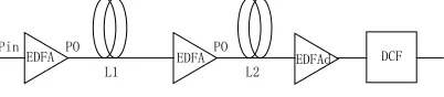
it will restore to its initial pulse width after each cycle. If the two segments of the fiber length is the same as GVD, and is opposite in sign. For the optical system has been built, it can choose a relatively short dispersion compensating fiber (DCF) in order to upgrade. The system implementation method is shown in Figure 2.
Pin PO PO
DCF EDFAd EDFA
EDFA
[image:3.612.318.519.355.399.2]L1 L2
Figure 2: DCF Dispersion Compensation System
In the long distance 1550nm non-dispersion displacement optical fiber transmission system, the focus of the study is choosing optimum length of two order intermodulation CSO minimum dispersion compensating fiber. According to the nonlinear Schrödinger equation, we get the CSO.
(
)
(
)
2 0 2 2 0 1 120lg[ { 1
2 2
1
[ ( 1)
1
1 ]}] 10log( ) (7)
d d
z
z d d d d d
d
z
d cso
CSO m P D e z
c
D P e z
P e z N
α
α
α
λ γ α
π α γ α α γ α − − −
= Ω + −
+ + −
+ − +
Where, P0 is the fiber optical power of main communication lines, Pd is input optical power of DCF, Dd is dispersion constant,
γ
d is nonlinearcoefficient, αd is loss constant, zd is the length of
ISSN: 1992-8645 www.jatit.org E-ISSN: 1817-3195
(
)
(
)
0 2 2
0
1 1
1 [ ( 1)
1
1 ] 0 (8)
d dz z
d d d d d d
z d
P D e z D P e z
P e z
α α
α
γ α γ α
α α
γ α
− −
−
+ − + + − +
− =
[image:4.612.320.515.346.499.2]When (8) is established, CSO can be eliminated. In order to meet the conditions, the length of dispersion compensating fiber has a decisive influence. When zd =0 , it has no dispersion compensation; zdis smaller, it is less dispersion compensation;
z
d is larger, it is dispersion compensation. Therefore,z
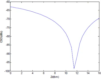
dis moderate, which are equal to full dispersion compensation. CSO will be zero in theory, and the actual data is minimum. Take non- dispersion displacement optical fiber and dispersion fiber data for calculation, the data is shown in Table 2. The length relation of COS and DCF is shown in Figure 4. It can be seen from the graph, when the DCF is -120ps/ nm /km, the optimum length of dispersion compensation fiber is slightly less than the 1/10 of non-dispersion shift fiber length.Table 2: Optical Fiber Data
Non dispersion shift fiber(z=115km)
Dispersion compensation fiber
P0 18dBm Pd 14dBm
γ
2.10×10⁻³/ W /mγ
d 5.02×10 -3/ W /m
D
17ps/ nm /km Dd -120ps/ nm /kmα
0.25dB/kmα
d 0.5dB/km4.2 Dispersion compensation with chirp fiber grating
The fiber chirp grating for dispersion compensation is based on fiber prague grating technology. The dispersion compensation fiber grating cycle is chirp or along the fiber direction of
periodic linear change smaller. And it does not have a high nonlinear, so this is the biggest disadvantage of the dispersion compensation fiber. Chirp grating has compensation ability, low cost, mature technology, and the optical fiber link upgrade easily. Along with the development of communication network transmission as well as the application of dense wavelength division multiplexing, fiber chirp grating has showed its large dispersion, such as high reflectivity, broad reflection bandwidth and other unique advantages. When the bit rate is 10Gbit/s, the system of dispersion tolerance capacity is become from 450ps to 60ps. In the dense wavelength division multiplexing system, chirp fiber gratings can be conveniently on various channels of precise dispersion compensation. In order to obtain a better network effect, chirp fiber grating dispersion compensation module and EDFA are placed apart, and the position z of DCM can be arbitrarily changed. As shown in figure 4.
Figure 3: The CSO And DCF Length Relationship
Figure4: Chirp Fiber Grating Dispersion Compensation System
The DCM can be seen as a special fiber which has great dispersion. Because the length is small, its damage and nonlinear is negligible. The output end CSO of long distance optical fiber system is as follows:
1
1
2 1
( )
2 0
1
1
( )
1 1
20lg{| [ [ ( ) (1 ) ( )]
2 2
[ ( ) (1 ) ( ] |} 10log( ) (9)
j j
j j
M
z z
j j
k
z z
g eff eff j CSO
j
CSO mP D S L e S L z
c
D L z e L z z N
α
α λ γ
π −
−
−
− −
= −
− −
=
= Ω + − −
+ + − − +
∑
∑
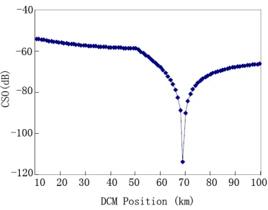
[image:4.612.133.496.552.625.2]According to the formula(9) , fiber length is 100km, and fiber parameters are in Table 2. Hypothesis dispersion of DCM is -1200ps/nm. Make z=10~100km, step is 2km , in 100km fiber, the output end of CSO indicators is shown in Figure 5. It can be seen from the figure, there is an optimal position, and it can make DCM completely offset the distortion which is induced by fiber.
Figure 5: CSO Position Changes With DCM
The chirp fiber grating can also be used for multi channel dispersion compensation. In order to make better use of single-mode fiber, wavelength division multiplexing ( WDM ) technology becomes the solution. But the dispersion compensation has become a problem to be solved. Usually the dispersion compensation is only narrow band light source, and grating to match the requirements. Using a plurality of such grating to multi channel for dispersion compensation grating. The multiple channels is similar to multiple single channel grating performance, but it has high stability ,when it is writing only in a section of the fiber. And the multi-channel grating cost are relatively low, so it is the very good solution in the WDM dispersion compensation.
5. CONCLUSIONS
Although there are many dispersion compensation methods, each kind of method has its own advantages and disadvantages. So far there is not a technique is optimal, and it mast be under certain conditions to achieve the optimal. In different transmission distance, each paragraph must adjust parameters to achieve the best results. The chirp technology is very effective in short distance communication, but it can not meet the requirements for dispersion compensation in long distance communication. Dispersion optical fiber compensation technology is better for less node system, when the node is large, it is difficult to
achieve. At the same time the spectrum inversion and the chirp technology is difficult to achieve, and the cost comparison is high. Therefore, it should also be based on the specific situation and analysis to choose the optimal technology of dispersion compensation.
With the project construction as the foothold in this paper, it will provide a reference method for the research and development of communications products, but also it provides a theoretical basis. Currently, the study on dispersion has developed deeply, but there is not a best method. There is no uniform dispersion compensation method in different communication systems. At the same time, the intelligent equipment still needs to be improved.
REFRENCES:
[1] H.C. Chang, H.S. Huang, J.S. Wu, Wave coupling between parallel single-mode and multimode optical fibers, IEEE Trans. Microwave Theory Tech. Vol.34 No. 12,1986 ,pp.1337-1343.
[2] Ye Wang, Dajian Xue, Xuanhui Lu, Power transfercharacteristicsamong N parallel single-modeopticalfibers. Optik , Vol.120,2009, pp. 242–246.
[3] Schermer RT. Mode scalability in bent optical fibers. Optics Express, Vol.15, 2007, pp.15674. [4] Yao L, Birks TA, Knight JC. Low bend loss in
tightly-bent fibers through adiabatic bend transitions. Optics Express, Vol.17 2009, pp. 2962.
[5] C. Elosua, C. Bariain, I.R. Matias, Optical fiber sensors to detect volatile organic compound in sick building syndrome applications, Open Construction and Building Technology Journal , Vol.4,2010,pp.113-120.
[6] Maravelakis, P.E., Castagliola, P.. An EWMA chart for monitoring the process standard deviation when parameters are estimated. Computational Statistics and Data Analysis, Vol. 53,2009, pp.2653-2664.
[7] C. Elosua, C. Bariain, A. Luquin, M. Laguna, I.R. Matias, Optimization of single mode fibre sensors to detect organic vapours, Sensors and Actuators B:Chemical, Vol. 157,2011,pp. 388– 394.
[8] M.H. Tu, T. Sun, K.T.V. Grattan, Optimization of gold-nanoparticle-based optical fibre surface plasmon resonance (SPR)-based sensors, Sensors and Actuators B:Chemical, 2012. [9] C.R. Zamarre˜no, M. Hernaez, I. Del Villar, I.R.
ISSN: 1992-8645 www.jatit.org E-ISSN: 1817-3195
based on lossy-mode resonances by means of thin polymeric coatings, Sensors and Actuators B: Chemical , Vol.155,2011,pp. 290-297. [10]C.R. Zamarre˜no, M. Hernaez, I. Del Villar, I.R.