1
B T P MADHAV, 2HARISH KAZA, 2THANNERU KARTHEEK, 2VIDYULLATHA LAKSHMI KAZA, 2SREERAMINENI PRASANTH, 2K S SANJAY CHANDRA SIKAKOLLU, 2MANEESH
THAMMISHETTI, 2ALUVALA SRINIVAS, 3K V L BHAVANI
1Member IEEE, Associate Professor, Department of ECE, K L University, India 2
Engineering Project Students, Department of ECE, K L University, India
3Graduate Engineering Student, Electrical Engineering Department, Santa Clara University, Santa Clara,US
E-mail: [email protected], [email protected]
ABSTRACT
A compact coplanar waveguide fed trapezoidal monopole antenna and a notch band monopole antenna are presented in this paper. Notch Band is obtained between 3-4 GHz, which covers S- band of WiMAX applications. The notch band antenna is obtained by etching U- slot on the radiating element of the monopole antenna. The proposed antenna is printed on Rogers RT- Duroid 5880 substrate material with dielectric constant 2.2 and loss tangent 0.0009. The overall dimension of the notch band antenna is around 51 x 45 x 1.6 mm. Initially Trapezoidal Notch band monopole antenna is constructed from the basic design of trapezoidal monopole wideband antenna and the corresponding antenna parameters and Radiation characteristics for both the models are analyzed and presented in detail in this article.
Keywords: Compact Antenna, S- Band, Trapezoidal Wideband Antenna, Trapezoidal Notch Antenna, Wimax.
1.
INTRODUCTIONMicrostrip antennas are widely used advanced devices in the modern communication systems because of several advantages such as Low Profile, Low Fabrication cost, simple in design and can be used in multi-band and wide-band applications [1-4]. The main disadvantage with these antennas is narrow band width, which is a serious problem for modern high speed data communication systems [5-8]. Different techniques are proposed by the researches from last one decade to overcome the limited band width problem and associated difficulties. Some of these techniques include increasing the thickness of the substrate, choosing low dielectric materials [9-14] and using parasitic patches etc. These techniques are also suffering with some of the problems associated with them like excitation of the surface waves and increase in antenna size. Surface waves related problems can be reduced by using electromagnetic band gap structures and metamaterial loaded designs in the antenna structure [15-16].
A part from the design issues, the problem with electromagnetic interference occurring due to
existing narrow band communication systems like WiMAX, WLAN and X- Band Satellite communication links is of major concern. Integration of external band stop filters to achieve the desired band rejection increases system complexity and size [17-20]. Hence, in order to keep the antenna footprint unaltered, designers have resorted to the approach of embedding parasitic strips or slots of different shapes in the radiating elements or ground plane of the antenna systems [21-23]. Moreover, many wideband applications require more than one notch band, necessitating the use of the mutually non interacting band notch elements. Different multiple band notched antenna topologies have also been reported in the literature.
In this paper, we proposed two antenna models, one for wideband applications and other for notch band characteristics with modifications in the first model. Substrate material plays an
important role in the design of the antenna and most of its parameters will vary with the selection of substrate material. Substrate permittivity effects on the performance of the notch band antenna is also performed and presented in this work.
2.
ANTENNA DESIGN SPECIFICATIONAntenna model 1 consisting of a trapezoidal monopole for wideband applications as shown in figure 1(a). Figure 1(b) shows the U-slot trapezoidal monopole for notch band operation. Figure 1(c) shows the dimensional characteristics of the slotted portion in the notch band trapezoidal monopole antenna. The overall dimensions of the proposed two models are tabulated in Table 1. Antenna 1 consisting of the overall dimension of 45 x 37 x 1.6 mm and antenna 2 consisting of the overall size of 51 x 43 x 1.6 mm. Both these models are printed on a dielectric material RT- Duroid 5880 with dielectric constant 2.2 and loss tangent 0.0009. The monopole element length and width are different in these two models and strictly speaking the dimensions of the monopole are slightly higher for notch band trapezoidal monopole antenna when compared with trapezoidal monopole antenna.
Fig.1.( a ) Trapezoidal Monopole Antenna
Fig.1.( b ) Trapezoidal Monopole Notch Antenna
Fig.1.( c ) Trapezoidal Monopole Slot Configuration
Fig.1.( d ) Side view of the monopole antenna models
Table 1. Trapezoidal Monopole Antenna Parameters
Name Parameter Trapezoidal Monopole
antenna Dimensions
Trapezoidal Monopole
Notch antenna Dimensions
Le
Monopole
element length 22.71 mm 25.93 mm
We
Monopole
element width 22.71 mm 25.93 mm
α Taper angle at
monopole base 30.13 ° 29.96 o
Sf Feed gap 50.46 μm 56.98 μm
Wg
Ground-plane
width 45.42 mm 51.86 mm
Lg
Ground-plane
length 37.85 mm 43.21 mm
Wgi
CPW inner
width 3.545 mm 4.052 mm
Wg0
CPW outer
width 3.785 mm 4.321 mm
ε
rRelative permittivity of
the dielectric
2.2 2.2
H Substrate height
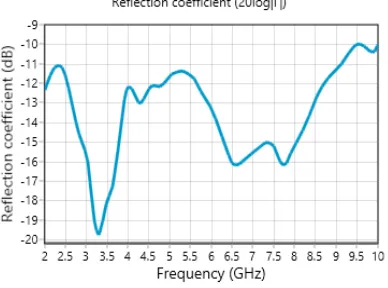
Figure 2(a) shows the reflection coefficient of the trapezoidal monopole antenna. A wide bandwidth of 9.5 GHz is attained from this antenna model. Figure 2(b) shows the reflection coefficient of trapezoidal notch band monopole antenna with band notch characteristics between 2.7-4.2 GHz. The pass band bandwidth of 5.3 GHz at higher band and 2.7 GHz at lower band can be observed from the result of notch band monopole antenna. Fig 3(a) and 3(b) shows the VSWR of the proposed models and their corresponding standing wave ratio values in their operating frequency band. Fig 4 shows the impedance matching characteristics of the antenna models in the operating frequency range. It is been observed from the figure 4(b) that the impedance value is far away from 50 ohms at notch band of antenna model 2. Figure 5 also shows the input impedance characteristics of both the models in smith chart.
Fig.2. (A) Reflection Coefficient Vs Frequency Trapezoidal Monopole Antenna
Fig.2. (B) Reflection Coefficient Vs Frequency Of Notch Antenna
Fig.3. (A) VSWR Vs Frequency Trapezoidal Monopole Antenna
Fig.3. (B) VSWR Vs Frequency Of Notch Antenna
[image:3.595.313.507.109.449.2] [image:3.595.313.505.142.304.2] [image:3.595.325.510.317.467.2] [image:3.595.93.287.373.517.2] [image:3.595.95.284.552.697.2]Fig.4. (a) Impedance Vs Frequency trapezoidal monopole antenna
Fig.4. (b) Impedance Vs Frequency of Notch antenna
Fig.5. (a) Smith Chart trapezoidal monopole antenna
Fig.5. (b) Smith Chart Vs Frequency of Notch antenna
Fig.6. Radiation Pattern of notch at 2.2 GHz, (a) Polar Plot
Fig.6. Radiation Pattern of notch at 2.2 GHz, (b) 2D-Plot
gain of more than 4.6 dB is attained at higher frequency band of operation.
Fig.7. Radiation Pattern of notch at 4.4 GHz, (a) Polar Plot
Fig.7. Radiation Pattern of notch at 4.4 GHz, (b) 2D-Plot
The dimensional characteristics of the monopole notch antenna is evaluated with change in substrate permittivity and tabulated in Table 2. The overall dimension of the antenna is decreased with increase in permittivity of the substrate material. The height of the substrate is kept constant throughout this process while calculating the dimensions of the monopole notch antenna.
Fig.8. Radiation Pattern of notch at 8.8 GHz, (a) Polar Plot
Fig.8. Radiation Pattern of notch at 8.8 GHz, (b) 2D-Plot
Fig.10. Three Dimensional Radiation pattern of the notch antenna at 2.2, 4.4 and 8.8 GHz
Table 2.1. Monopole Notch Antenna dimensions with change in substrate permittivity
Name Parameter
ε
r=2.9
ε
r=3.1Le
Monopole
element length 21.95 mm 21.71 mm
We
Monopole
element width 21.95 mm 21.71 mm
α
Taper angle at monopole
base
33.39 ° 34.39 °
Sf Feed gap 58.91 μm 59.31 μm
Wg
Ground-plane
width 43.90 mm 43.43 mm
Lg
Ground-plane
length 36.58 mm 36.19 mm
Wgi
CPW inner
width 3.312 mm 3.243 mm
Wg0
CPW outer
width 3.658 mm 3.619 mm
ε
rRelative permittivity of
the Dielectric
2.9 3.1
H Substrate height
1.6 mm 1.6 mm
Table 2.2. Monopole Notch Antenna dimensions with change in substrate permittivity
Name Parameter
ε
r=3.9
ε
r=4.4Le
Monopole
element length 15.25 mm 15.19 mm
We
Monopole
element width 15.25 mm 15.19 mm
α
Taper angle at
monopole base 36.01 ° 36 °
Sf Feed gap 52.62 μm 61.62 μm
Wg
Ground-plane
width 30.51 mm 30.37 mm
Lg
Ground-plane
length 25.42 mm 25.31 mm
Wgi
CPW inner
width 2.157 mm 2.080 mm
Wg0
CPW outer
width 2.542 mm 2.531 mm
ε
rRelative permittivity of
the dielectric
3.9 4.4
H Substrate height
1.6 mm 1.6 mm
4. CONCLUSION
Authors likes to express their gratitude towards the department of ECE and management of K.L. University for their continuous support and encouragement during this work. B T P Madhav also likes to express his thanks to the LCRC-R&D director Dr. VGKM Pisipati and Er. K Satyanarayana, President, KLU for providing excellent resources at KLU to the researchers.
REFRENCES:
[1] B.T.P.Madhav, VGKM Pisipati, K V L Bhavani, P.Sreekanth, P.Rakesh Kumar, “Rectangular Microstrip Patch Antenna on Liquid Crystal Polymer Substrate”, Journal of Theoretical and Applied Information Technology (JATIT), Volume 18, No 1, August 2010, pp. 62 – 66.
[2] B.T.P.Madhav, VGKM Pisipati, Prof. Habibulla Khan, VGNS Prasad, Prof. KSN Murty , “Ultra Wide Band Liquid Crystal Polymer Microstrip Elliptical Patch Antenna”,
Journal of Theoretical and Applied Information Technology (JATIT) , Volume 20, No 1, October 2010, PP. 105 – 109.
[3] B.T.P. Madhav, P. Syamsundar, A. Ajay Gowtham,Chitta Vaishnavi, M. Gayatri Devi, G. Sahithi Krishnaveni, “Elliptical Shaped Coplanar Waveguide, Feed Monopole Antenna”, World Applied Sciences Journal, ISSN 1818-4952, Volume 32, Issue 11, 2014, pp 2285-2290.
[4] [3] C. Deng, Y.-J. Xio, and P. Li, “CPW-fed planar printed monopole antenna with impedance bandwidth enhanced”, IEEE Antennas Wireless Propagation Letters, Volume 8, 2009, pp. 1394–1397.
[5] D.Rakesh, P.Rakesh Kumar, B.T.P.Madhav, Habibulla Khan K Ch Sri Kavya, K.Prabhu Kumar, S Bala Durga Prasad, “Performance Evaluation Of Microstrip Square Patch Antenna On Different Substrate Materials”,
Journal of Theoretical and Applied InformationTechnology, Volume 26, No 2, April 2011, pp. 97 – 106.
[6] K.Prabhu Kumar, P.S.Brahmanandam, B.T.P.Madhav , K Ch Sri Kavya, V.Shiva Kumar, T.RaghavendraVishnu, D.Rakesh, “Uniplanar Quasi Yagi Antenna For Channel
Theoretical and Applied Information Technology (JATIT), Volume 26 No 2, April 2011.
[7] B.T.P.Madhav, VGKM Pisipati1, Habibulla Khan, V.G.N.S Prasad, K. Praveen Kumar, KVL Bhavani and M.Ravi Kumar, “ Liquid Crystal Bow-Tie Microstrip antenna for Wireless Communication Applications”,
Journal of Engineering Science and Technology Review, ISSN: 1791-2377 , Volume 4, No 2, 2011, pp. 131 - 134.
[8] R. Zaker and A. Abdipour, “A very compact ultrawideband printed omnidirectional monopole antenna,” IEEE Antennas Wireless Propagation Letters, Volume 9, 2010, pp. 471– 473.
[9] B T P Madhav, Habibulla Khan, D Ujwala, Y Bhavani Sankar, Madhuri Kandepi, A Siva Nagendra Reddy, Davuluri Nagajyothi, “CPW Fed Serrated Antenna Performance Based on Substrate Permittivity”, International Journal of Applied Engineering Research, ISSN 0973-4562, Volume 8, Number 12, Nov-2013, pp. 1349-1354.
[10]Y. Sung, “Triple band-notched UWB planar monopole antenna using a modified H-shaped resonator,” IEEE Trans. Antennas Propagations, Volume 61, no. 2, Feb. 2013, pp. 953–957.
[11]M. Ojaroudi, N. Ojaroudi, and N. Ghadimi, “Dual band-notched small monopole antenna with novel coupled inverted U-ring strip and novel fork-shaped slit for UWB applications,”
IEEE Antennas Wireless Propagation Letters, Volume 12, 2013, pp. 182–185.
[12]M. J. Almalkawi and V. K. Devabhaktuni, “Quad band-notched UWB antenna compatible with WiMAX/INSAT/lower-upper WLAN applications”, Electronic Letters, Volume 47, no. 19, Sep. 2011, pp. 1062–1063.
[13]M. Al-Husseini, J. C ostantine, C. G. C hristodoulou, S. E. Barbin, A. El-Hajj, and K. Y. Kabalan, “A reconfigurable frequency-notched UWB antenna with split-ring resonators,” in Proc. Asia-Pacific Microwave Conference, Dec. 2012, pp. 618–621.
[14] Habibulla Khan, B.T.P. Madhav, K. Mallikarjun, K. Bhaskar, N. Sri Harsha and
Muralidhar Nakka, “Uniplanar
[15] B T P Madhav, Krishnam Naidu Yedla, G.S.,
Kumar, K.V.V., Rahul, R., , “Fractal aperture EBG ground structured dual band planar slot antenna”, International Journal of Applied Engineering Research, ISSN 0973-4562, Volume 9, Number 5, Jan-2014, pp 515-524. [16] B T P Madhav, VGKM Pisipati,
Habibulla Khan, D Ujwala, “ Fractal shaped Sierpinski on EBG structured ground plane”,
Leonardo Electronic Journal of Practices and Technologies, ISSN 1583-1078, Issue 25, July-December 2014, pp 26-35.
[17] B. T. P. Madhav, Sarat K. Kotamraju, P. Manikanta, K. Narendra, M. R. Kishore and G. Kiran, “Tapered Step CPW-Fed Antenna for Wideband Applications”, ARPN Journal of Engineering and Applied Sciences, ISSN 1819-6608, Volume 9, No 10, October-2014, pp 1967-1973.
[18] B.T.P.Madhav, S. S. Mohan Reddy, Bandi Sanjay, D.Ujwala, “Trident Shaped Ultra Wideband Antenna Analysis based on Substrate Permittivity”, International Journal of Applied Engineering Research, ISSN 0973-4562, Volume 8, Number 12, Nov-2013, pp. 1355-1361.
[19] B T P Madhav, K V V Kumar, A V Manjusha, P Ram Bhupal Chowdary, L Sneha, P Renu Kantham, “Analysis of CPW Fed Step Serrated Ultra Wide Band Antenna on Rogers RT/Duroid Substrates”, International Journal of Applied Engineering Research, ISSN 0973- 4562, Volume 9, Number 1, Jan-2014, pp. 53-58.
[20] B T P Madhav, Habibulla Khan, D Ujwala, Y Bhavani Sankar, Madhuri Kandepi, A Siva Nagendra Reddy, Davuluri Nagajyothi, “CPW Fed Serrated Antenna Performance Based on Substrate Permittivity”, International Journal of Applied Engineering Research, ISSN 0973-4562, Volume 8, Number 12, Nov-2013, pp. 1349-1354.
[21]Y. Zhang, W. Hong, C. Yu, Z.-Q. Kuai, Y.-D. Don, and J.-Y. Zhou, “Planar ultra wideband antennas with multiple notched bands based on etched slots on the patch and/or split ring resonators on the feed line”, IEEE Tranactions and Antenna Propagations, Volume 56, no. 9, Sep. 2008, pp. 3063–3068.
[22]C. C. Lin and R. W. Ziolkowski, “Tri-band notched ultra-wideband antenna using capacitively loaded loops (C LLs)”, in Proc.
IEEE Antennas Propagation Soc. Int. Symposium, Jul. 2010, pp. 1–4.