Order No. AA-K181A-TK
DECnet
DIGITAL Network Architecture
Network Management
Functional Specification
DEenet
DIGITAL Network Architecture
(Phase III)
Network Management
Functional Specification
Order No. AA-K181 A-TK
Version 2.0.0
October 1980
This document describes the functions, structures, protocols, algorithms, and operation of the DIGITAL Network Architec-ture Network Management modules. It is a model for DECnet implementations of Network Management software. Network Management provides control and observation of DECnet net-work functions to users and programs.
First Printing, October 1980
This material may be copied, in whole or in part, provided that the copyright notice below in included in each copy along with an
acknowledgment that the copy describes protocols, algorithms, and structures developed by Digital Equipment Corporation.
This material may be changed without notice by Digital Equipment Corporation, and Digital Equipment Corporation is not responsible for any errors which may appear herein.
Copyright
~
1980 by Digital Equipment CorporationThe postage-prepaid READER'S COMMENTS form on the last page of this document requests the user's critical evaluation to assist us in pre-paring future documentation.
The following are trademarks of Digital Equipment Corporation:
DIGITAL DEC PDP DECUS UNIBUS
COMPUTER LABS COMTEX
DDT DECCOMM ASSIST-II VAX
DECnet DATATRIEVE
DECsystem-lO DECtape DIBOL EDUSYSTEM FLIP CHIP FOCAL INDAC LAB-8
DECSYSTEM-20 RTS-8
VMS lAS TRAX
MASSBUS OMNIBUS OS/8 PHA RSTS RSX
TYPESET-8 TYPESET-ll TMS-ll ITPS-IO .SBI
1.0 2.0 2.1 2.2 2.3 3.0 3.1 3.1.1 3.1.2 3.1.3 3.1.4 3.1.5 3.1.6 3.2 3.2.1 3.2.2 3.2.3 3.2.4 3.2.5 3.2.6 3.3 3.3.1 3.3.1.1 3.3.1.2 3.3.1.3 3.3.1.4 3.3.1.5 3.3.2 3.3.2.1 3.3.2.2 3.3.2.3 3.3.2.4 3.3.2.5 3.3.3 3.3.4 3.3.4.1 3.3.4.2 3.3.5 3.3.6 3.3.6.1 3.3.6.2 3.3.7 3.3.8 3.3.8.1 3.3.8.2 3.3.8.3 3.3.8.4 3.3.9 3.3.10 4.0 CONTENTS INTRODUCTION
FUNCTIONAL DESCRIPTION Design Scope
Relationship to DIGITAL Network Architecture Functional Organization within DIGITAL Network Architecture
NETWORK CONTROL PROGRAM (NCP)
Network Control Program Functions Changing Parameters
Gathering Information Down-line Loading Up-line Dumping
Testing Line and Network Zeroing Counters
Network Control Program Operation Specifying the Executor
Program Invocation, Termination, and Prompting Privileged Commands
Input Formats
Output Characteristics Status and Error Messages
Network Control Program Commands SET and DEFINE Commands
SET and DEFINE EXECUTOR NODE destination-node SET and DEFINE KNOWN Entity Commands
SET and DEFINE LINE Commands SET and DEFINE LOGGING Commands SET and DEFINE NODE Commands CLEAR and PURGE Commands
CLEAR and PURGE EXECUTOR NODE Commands CLEAR and PURGE KNOWN Entity Commands CLEAR and PURGE LINE Commands
CLEAR and PURGE LOGGING Commands CLEAR and PURGE NODE Commands TRIGGER Command
LOAD Command LOAD NODE Command LOAD VIA Command DUMP Command LOOP Command LOOP LINE Command LOOP NODE Command SHOW QUEUE Command SHOW and LIST Commands
Information Type Display Format Counter Display Format
Tabular and Sentence Formats Restrictions and Rules on Returns ZERO Command
EXIT Command
NETWORK MANAGEMENT LAYER
4.1 4.1.1 4.1.2 4.1.3 4.1.4 4.1.4.1 4.1.4.2 4.1.4.3 4.1.4.4 4.1.5 4.1.5.1 4.1.5.2 4.2 4.2.1 4.2.2 4.2.3 4.2.4 4.2.4.1 4.2.4.2 4.2.5 4.2.6 4.2.7 4.2.8 4.2.9 4.2.10 4.3 4.3.1 4.3.2 4.3.3 4.3.4 4.3.5 4.3.6 4.3.7 4.3.8 4.3.9 4.3.10 4.3.11 4.3.12 4.3.13 5.0 5.1 5.2 5.3 5.3.1 5.3.2 5.3.3
CONTENTS (Con t. )
Network Management Layer Modules
Network Management Access Routines and Listener Local Network Management Functions
Line Watcher
Line Service Functions States and Substates Priority Control Line State Algorithms Line Handling Functions Event Logger
Event Logger Components
Suggested Formats for Logging Data Network Management Layer Operation Down-line Load Operation
Up-line Dump Operation Trigger Bootstrap Operation Loop Test Operation
Node Level Testing Data Link Testing
Change Parameter Operation Read Information Operation Zero Counters Operation NICE Logical Link Handling
Algorithm for Accepting Version Numbers Return Code Handling
Network Management Layer Messages NICE Function Codes
Message and Data Type Format Notation Request Down-line Load Message Format Request Up-line Dump Message Format Trigger Bootstrap Message Format Test Message Format
Change Parameter Message Format Read Information Message Format Zero Counters Message Format
NICE System Specific Message Format NICE Response Message Format
NICE Connect and Accept Data Formats Event Message Binary Data Format
APPLICATION LAYER NETWORK MANAGEMENT FUNCTIONS Loopback Mirror Modules
Loopback Mirror Operation Logical Loopback Message Connect Accept Data Format Command Message Format Response Message
APPENDIX A NETWORK MANAGEMENT ENTITIES, PARAMETERS AND
A.1 A.1.1 A.1.2 A.2 A.3 A.3.1 A.3.2 APPENDIX
COUNTERS: FORMATS AND DATA BLOCKS LINE Entity
Line Parameters Line Counters LOGGING Entity NODE Entity Node Parameters Node Counters
B MEMORY IMAGE FORMATS
CONTENTS (Cont.)
Page
APPENDIX C MEMORY IMAGE FILE CONTENTS 105
106
I I I
113 113 113 115 123 125 APPENDIX D
APPENDIX E APPENDIX F F.l
F.2 F.3
APPENDIX G APPENDIX H APPENDIX I
GLOSSARY
FIGURE 1 2 3 4 5 6 7 8
NICE RETURN CODES WITH EXPLANATIONS NCP COMMAND STATUS AND ERROR MESSAGES EVENTS
Event Class Definitions Event Definitions
Event Parameter Definitions JULIAN HALF-DAY ALGORITHMS DMC DEVICE COUNTERS
NCP COMMANDS SUPPORTING EACH NETWORK MANAGEMENT INTERFACE
FIGURES
126
135
Network Management Relation to DNA 6
Network Management Layer Modules and Interfaces in a
Single Node 8
Event Logging Architectural Model 51
Down-line Load File Access Operation 57
Down-line Load Request Operation 59
Examples of Node Level Testing Using a Loopback Node
Name with and without the Loopback Mirror 64
Examples of Node Level Logical Link Loopback Test
with and without the Loopback Mirror 65
Physical Link Loopback Tests and Command Sequences
Effecting Them 67
TABLES
TABLE 1 NCP Commands 16
40 41 2 Network Management Line States
3 Line State Transitions
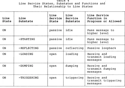
4 Line Service States, Substates and Functions and Their Relationship to Line States
5 DECnet Line Devices 6 Line Parameters 7 Line Counters
8 Logging Parameters 9 Node Parameters 10 Node Counters 11 Event Classes 12 Events
1.0 INTRODUCTION
This document describes the structure, functions, operation, and protocols of Network Management. Network Management 1S that part of
the DIGITAL Network Architecture that models the software that enables operators and programs to plan, control, and maintain the operation of centralized or distributed DECnet networks. DIGITAL Network Architecture (DNA) is the model on which DECnet network software implementations are based. Network software is the family of software modules, data bases, hardware components, and facilities used to tie DIGITAL systems together in a network for resource sharing, distributed computation, or remote system communication.
DNA is a layered structure. Modules in each layer perform distinct functions. Modules within the same layer (either in the same or different nodes) communicate using specific protocols. The protocols specified in this document are the Network Information and Control Exchange (NICE) protocol, the Loopback Mirror protocol, and the Event Receiver protocol.
Modules in different layers interface using subroutine calls or a similar system-dependent method. In this document, interface communications between layers are referred to as calls or requests because this is the most convenient way of describing them functionally. An implementation need not be written as calls to subroutines. Interfaces to other DNA layers are not specified in detail, however, Appendix I describes which Network Management user commands (Network Control Program) support each DNA interface.
In this document network nodes are described by function as executor, command, host, and target. The executor is an active network node connected to one end of a line being used for a load, dump, or line loop test and is the node that executes requests. The command node is the node in which the Network Management request originates. The host is a node that provides a higher level service such as a file system. The target is a node that is to receive a load, loop back a test message, or generate a dump. Executor, command, and host nodes may be three different nodes, all the same node, or any combination of two nodes. A glossary at the end of this document defines many Network Management terms.
This document describes commands that can be standardized across different DECnet implementations. An implementation may use only a subset of the commands described herein. Moreover, commands and functions specific to one particular operating system are not described.
This is one of a series of functional specifications for the DIGITAL Network Architecture, Phase III. This document assumes that the reader is familiar with computer communications and DECnet. The primary audience for this specification consists of implementers of DECnet systems, but it may be of interest to anyone wishing to know details of DECnet structure. The other DNA Phase III functional specifications are:
DNA Data Access Protocol (DAP) Functional Specification, Version 5.6.0, Order No. AA-K177A-TK
D =-::..;.N..:...:A_-::D::-=i~gL..:l=-· t~a:;:.=.l_..;;:.D~a:...:t:....::a-=--.:::-_C=-o=-m:.;.:.::.;:;m~u..::..:n:....::i~c:....::a;:-t.=-l=-· o=-n=s~~M.:..:e::....:s;....:s=-a:.::...g,L..:;:....e--.~p. rot 0 col ( DDC M P) Functional Specification, version 4.l~0, Order No. AA-K175A-TK
DNA Maintenance Operations Protocol (MOP) Functional
Specification, version 2.1.0, Order No. AA-K178A-TK
DNA Network Services 3.2.0, Order No.
(NSP) Functional AA-K176A-TK
Specification, version
DNA Transport Functional Specification, version 1.3.0, Order No. AA-K180A-TK
DNA Session Control Functional Specification, version 1.0.0, Order No. AA-K182A-TK
2.0 FUNCTIONAL DESCRIPTION
Network Management enables operators and programs to control and monitor network operation. Network Management helps the manager of a network to plan its evolution. Network Management also facilitates detection, isolation, and resolution of conditions that impede effective network use.
Network Management provides user commands and capability to user programs for performing the following control functions:
1. Loading remote systems. A system in one node can down-line load a system in another node in the same network.
2. Configuring resources. A system manager can change the network configuration and modify message traffic patterns.
3. Setting parameters. Line, node, and logging parameters (for example, node names) can be set and changed.
4. Initiating and terminating network functions. A manager or operator can turn the network on or perform loopback tests and other functions.
system off and
Network Management also enables the user to monitor network functions, configurations, and states, as follows:
1. Dumping remote systems. A system in one node can up-line dump a system to another node in the same network.
2. Examining configuration status. Information about lines and nodes can be obtained. For example, an operator can display the states of lines and nodes or the names of adjacent nodes.
3. Examining parameters. Line and node parameters (for example, timer settings, line type, or node names) can be read.
4. Examining the status of network operations. An operator can monitor network operations. For example, the operator can find out what operations are in progress and whether any have failed.
5. Examining performance variables. A system manager can examine the contents of counters in lower DNA layers to
measure network performance. In addition, Network
Management's Event Logger provides automatic logging of significant network events.
Besides controlling and monitoring the day-to-day operation of the network, the functions listed above work to collect information for
future planning. These functions furnish basic operations
(primitives) for detecting failures, isolating problems, and repairing and restoring a network.
2.1 Design Scope
Network Management
requirements: functions satisfy the following design
quality of existing products. There is a compromise between the compatibility of network commands across heterogeneous systems and the compatibility within a system between network and other local system commands.
2. Subsetability. Nodes are able to support a subset of Network Management components or functions.
3. Ease of use. Invoking and understanding Network Management functions are easy for the operator or user programmer.
4. Network efficiency. Network Management is both processing and memory efficient. It is line efficient where this does not conflict with other goals.
5. Extensibility. There is accommodation for future, additional management functions, leaving earlier functions as a compatible subset. This specification serves as a basis for building more sophisticated network management programs.
6. Heterogeneity. Network Management operates across a mixture of network node types, communication lines, topologies, and among different versions of Network Management software.
7. Robustness. The effects of errors such as operator input errors, protocol errors, and hardware errors are minimized.
8. Security. Network Management supports the existing security mechanisms in the DIGITAL Network Architecture (for example, the access control mechanism of the Session Control layer).
9. Simplicity. Complex algorithms and data bases are avoided.
10.
Functions provided elsewhere in the architecture are not duplicated.
Support of diverse management policies. Network covers a range between completely centralized distributed management.
Management and fully
The following are not within the scope of Version 2.0.0 of Network Management:
1. Accounting. This specification does not provide for the recording of usage data that would be used to keep track of individual accounts for purposes of reporting on or charging users.
2. Automation. This specification does not provide for automatic execution of complex algorithms that handle network repair or reconfiguration. More automation can be expected in future revisions of this specification.
3. Protection against malicious use. There is no foolproof protection against malicious use or gross errors by operators or programs.
2.2 Relationship to DIGITAL Network Architecture
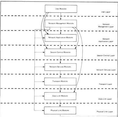
DIGITAL Network Architecture (DNA), the model upon which DECnet implementations are based, outlines several functional layers, each with its own specific modules, protocols, and interfaces to adjacent layers. Network Management modules reside in the three highest layers.
The general design of DNA is as follows in order from the highest to the lowest layer:
1. The User layer. The User layer is the supports user services and programs. Program (NCP) resides in this layer.
highest layer. It The Network Control
2. The Network Management layer. The Network Management layer is the only one that has direct access to each lower layer for control purposes . . Modules in this layer provide user control over, and access to, network parameters and counters. Network Management modules also perform up-line dumping, down-line loading, and testing functions.
3. The Network Application layer. Modules in the Network Application layer support I/O device and file access functions. The Network Management module within this layer is the Loopback Mirror, providing logical link loopback testing.
4. The Session Control layer. The Session Control layer manages the system-dependent aspects of logical link communication.
5. The Network Services layer. The Network Services layer controls the creation, maintenance, and destruction of logical links, using the Network Services Protocol and modules.
6. The Transport layer. Modules in the Transport layer route messages between source and destination nodes.
7. The Data Link layer. communications over a protocol, for example, Message Protocol (DDCMP).
The Data Link layer manages the physical link, uSlng a data link the Digital Data Communications
8. The Physical Link layer. The Physical Link layer provides the hardware interfaces (such as EIA RS-232-C or CCITT V.24) to specific system devices.
User Modules
Physical Link Modules
Network Management Laver
Network Application Laver
Session Control Laver
Network Services Laver
Transport Laver
Data Link Laver
Phvsical Link Laver
Horizontal arrows show direct access for control and examination of parameters, counters, etc. Vertical and curved arrows show interfaces between layers for normal user operations such as fde acces~, down·llne load, up·line dump, end·lo·end looping, and logical link usage.
Figure 1 Network Management Relation to DNA
2.3 Functional Organization within DIGITAL Network Architecture
The functional components of Network Management are as follows:
User layer components
Network Control Program (NCP). The Network Control Program
enables the operator to control and observe the network from a
terminal. Section 3 specifies NCP.
Network Management layer components
Section 4 specifies the Network Management layer components and
their operation. Figure 2 shows the relationship of Network
Management layer modules in a single node.
Network Management Access Routines. These routines provide user
[image:13.613.110.497.53.438.2]Network Management Listener. The Network Management Listener receives Network Management commands from the Network Management level of remote nodes, via the NICE protocol. In some implementations it also receives commands from the local Network Management Access Routines via the NICE protocol. It passes these requests to the Local Network Management Function.
Local Network Management Functions. These take function requests from the Network Management Listener and the Network Management Access Routines and convert them to system dependent calls. They also provide interfaces to lower level modules directly for control purposes.
Line Watcher. The Line Watcher is a module in a node that can sense service requests on a line from a physically adjacent node. It controls automatically-sensed down-line load or up-line dump requests.
Line Service Functions. These provide the Line Watcher and the Local Network Management Functions with line services needed for service functions that require a direct interface to the data link layer (line level testing, down-line loading, up-line dumping, triggering a remote system's bootstrap loader and setting the fine state). The Line Service module maintains internal states as well as line substates.
Event Logger. The Event Logger provides the capability of logging significant events for operator intervention or future reference. The process concerned with the event (for example, the Transport module) provides the data to the Event Logger, which can then record it.
Network Application Layer Components
Loopback Mirror. Access and service routines communicate using the Logical Loopback Protocol to provide node level loopback on logical links. Section 5 describes this Network Application layer component.
Object Types
The Network object types.
Management architecture requires three Each has a unique object type number.
The object types and numbers are:
Type Object Type Number
Network Management
Listener 19
Loopback Mirror 25
Event Receiver 26
NCP
~---Line Watcher
Network
NICE Management Protocol commands .... -to other
nodes
-~
System- ~
Independent Function Requests
Network Management Access Routines
User Program
NICE
i-P..!:o..!.o.£~ Management Network
Listener
User Layer
-
-
--Network Management ... - - - - commands
from other nodes
Local Network Management Functions
Line Service Functions
!
Events to~~r_n~~:~ _ _ ----"""f4- __ Events from other nodes Event Logger
Network Management Layer
---~---
- - - - .1- - - - - - - - - - --Service interface to Data Link Layer (down-line load, up-line dump, line tests, line state change)
Control over lower level ... functions (examine line state, turn on NSP, etc.)
System-dependent calls to application layer and local operating system functions (file access, logical link loopback, timer setting, etc.)
LatNer Layers
Control interface to read event queues
~---LEGEND:
NCP - Network Control Program NICE - Network Information and
Control Exchange
Figure 2 and
+ -
Vertical arrowheads indicate interfaces for function requests~ - Horizontal arrowheads indicate control interfaces
[image:15.612.96.526.32.594.2]3.0 NETWORK CONTROL PROGRAM (NCP)
This section is divided into three parts. Section 3.1 describes the NCP functions. Section 3.2 provides rules for the operation of NCP, including such topics as input and output formatting, access control, and status and error messages. Section 3.3 presents a detailed description of all the NCP commands.
3.1 Network Control Program Functions
There are two types of NCP commands:
1. Internal commands. These are directed to NCP itself and cannot be sent to remote nodes. Theie are the SET and DEFINE EXECUTOR NODE node-id, CLEAR and PURGE EXECUTOR NODE, and SHOW QUEUE commands; the TELL prefix; and the EXIT command
(Section 3.2).
2. Commands that use the Network Management interface. These use the Network Management Listener, via the Network Information and Control Exchange (NICE) protocol, when sent across logical links to remote nodes. NCP commands directed to the local node have the option of either using the Network Management Listener, via the Network Management Access Routines and the NICE protocol, or of passing requests directly to the Local Network Management Function from the Network Management Access Routines. The method chosen is implementation-specific.
The NCP command language enables an operator to perform the following network functions:
• Changing parameters (Section 3.1.1)
• Gathering information (Section 3.1.2)
• Down-line loading (Section 3.1.3)
• Up-line dumping (Section 3.1.4)
• Testing line and network (Section 3.1.5)
• Zeroing counters (Section 3.1.6)
3.1.1 Changing Parameters - The parameters are line, node, or logging options specifically described in Appendix A.
Some examples of changing parameters are:
• Setting a line state to ON
• Changing a node name associated with a node address
• Setting the routing cost for a line
Parameters may be set either as dynamic values in volatile memory using the SET command or as permanent values in a mass-storage default data base using the DEFINE command. The volatile data base is lost when the node shuts down; the permanent data base remains from one system initialization to the next. Parameters can be either status, such as line state, or characteristics that are determined by SET, DEFINE, CLEAR, and PURGE commands. Characteristics are static in the sense that once set, either at system generation time or by an operator, they remain constant until cleared or reset. Status consists of dynamic information (such as line state) that changes automatically when functions are performed.
Permanent values take effect whenever the permanent data base is
re-read. The timing of the values' taking effect is
implementation-dependent. Volatile values take effect immediately.
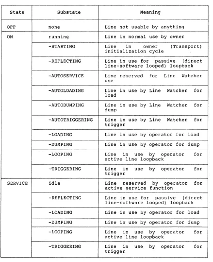
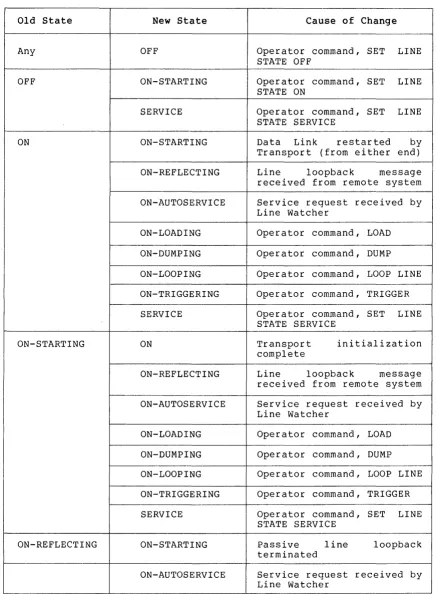
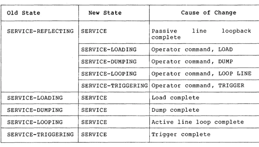
Setting line states does not change line ownership, which is Transport or its equivalent. Line states can be set, however, to control the use of the line by its owner. To Transport, the line is either OFF or ON. To Network Management, a line can also be in a SERVICE state, a state which precludes normal traffic, and which temporarily prevents Transport from using the line. The SERVICE state is used for loading, dumping, and line testing. The ON and SERVICE states have various substates that inform the operator what function the line is performing. When states are displayed, the substates are indicated as a tag on the end of the operator-requested state.
3.1.2 Gathering Information - The information gathered includes characteristics, status, and counters associated with the line, logging, and node entities (detailed in Appendix A). Examples of gathering information are:
• Displaying the state of a line
• Reading and then zeroing line counters
• Displaying characteristics of all reachable nodes
• Showing the status of all commands in progress at a node
Characteristics and status are described in Section 3.1.1.
Counters are error and performance statistics such as messages sent and received, time last zeroed, and maximum number of logical links in use.
3.1.3 Down-line Loading - Down-line loading is the process of transferring a memory image from a file to a target system's memory. This requires that the executor, the node executing the command, have direct access to the line to the target. The file may be located at another remote node, in which case the executor uses its system-specific remote file access procedures. The executor supports or has access to a data base of defaults for a load request. Section 4.2.1 describes the down-line load operation in the Network Management layer.
3.1.5 Testing Line and Network - Testing line and network can be accomplished by message looping at both the line and node levels. Testing requires receiving a transmitted message over a particular path that is looped back to the local node by either hardware or software.
Node level testing uses logical links and normal line usage. The lines involved are in the ON state, and the Session Control, Network Services, and Transport layers are used.
During line level testing, the line being tested is in the SERVICE state; normal usage is precluded. Network Management accesses the Data Link layer directly, bypassing intermediate layers. Section 4.2.4 describes line and network testing.
3.1.6 Zeroing Counters - Using NCP, an operator can set line and node counters to zero.
3.2 Network Control Program Operation
This section describes general rules concerning the operation of NCP.
The SET, DEFINE, CLEAR, and PURGE commands must successfully act on either all parameters entered or on none of them. One parameter per command is all that can be expected to take effect on any system, although a system may allow some parameters to be grouped on the same command.
3.2.1 Specifying the Executor - Since a command does not have to be executed at the node where it is typed, the operator must be able to designate on what node the command is to be processed. The operator has two options for controlling this:
1. Specifying a default executor for a set of commands
2. Naming the executor with the commad
At NCP start-up time, the default executor is the node on which NCP is running or the node that was previously defined with the DEFINE EXECUTOR NODE command. The default executor is changed using the SET, DEFINE, CLEAR, or PURGE EXECUTOR NODE commands (see Sections 3.3.1.2 and 3.3.2.1).
3.2.2 Program Invocation, Termination, and Prompting - The way NCP is
invoked
or terminated is system-dependent.
If a name is used for the
program, it must be "NCP.II The EXIT command terminates NCP.
The following rules apply to the initial NCP prompt:
For an NCP that accepts only a single outstanding command, the
p~omptis always the same:
NCP>
For an NCP that accepts
several
outstanding
commands
where
it is
obvious that NCP is prompting, the prompt is:
tn>
For the multiple-outstanding-command case where it is not obvious that
NCP is prompting, the prompt is:
NCf'tn>
In any case, n is the command's request number,
which
will
identify
the output for the command.
An implementation that cannot integrate the request
number
with
the
prompt, can display the request number when the command is accepted.
3.2.3 Privileged Commands - Network
and
determine which
commands should be limited
exact determination of
privilege
is an
function.
Privilege is generally determined
according to the privileges of the local user
provided at logical link connection time.
system
planners
must
to privileged users.
The
implementation-dependent
in a system-specific way
or
the
access control
3.2.4
Input Formats - Command input
is in
the
form
of
arguments
delimited by tabs or blanks.
Either a single or multiple tab or blank
may be used to delimit arguments.
Null command lines.
Null command
lines will
result
in
a
command
prompt being re-issued.
Node identification and
access control.
Nodes
are
identified
by
address or name.
The primary identification is the address (a Session
Control requirement).
The keyword EXECUTOR
can
be
substituted
for
NODE
executor~node-identification.If
a
node
identification
represents a node to be connected to, access control
information may
be
necessary or desired.
If so, the access control follows the node
identification, the maximum length of each
field
being
39
bytes.
Specific
systems may
limit the amount of access control information
they will accept.
The format is:
{
LOOP NODE
}
SET EXECUTOR NODE node-id [USER user-id] [PASSWORD password] [ACCOUNT account]
TELL
where:
SET EXECUTOR NODE node-id Is an NCP command used to set the node identification and access control for the default executor node (Section 3.3.1.1). The access control prevails until changed by another SET EXECUTOR command or a TELL or LOOP NODE command.
TELL node-id Is an NCP command prefix used to pass one command and access control information to a specific node. The access control applies only to that one command.
[USER user-id] Is access control information that provides the identification of the user.
[PASSWORD password]
[ACCOUNT account]
For example:
Is access control. information furnishing a password.
Is access control information supplying an account identification.
TELL BOSS USER (211,1] PASSWORD secret ACCOUNT x~z CLEAR KNOWN LINES
SET EXECUTOR NODE 97 ACCOUNT x~z
String input. String input (every argument that is not a node name, keyword or number) is defined by the executor node and the length limitations of the NICE protocol. For consistency from one implementation to another, the following rules apply to NCP's parsing algorithm for these types of arguments:
• Implementations will provide both a transparent and a non-transparent technique for specifying these arguments.
• The transparent technique will act on any string of characters enclosed in quotation marks ("XXXXX"). A quote within the string will be indicated by a double quotation mark
( II XXX II II XX ") .
• The non-transparent technique will act on any string of characters that does not contain blanks or tabs. An exception to this occurs where it is possible to recognize syntactically that blanks or tabs are not intended as delimiters.
Keywords. Implementations must accept keywords in their entirety. However, the user may abbreviate keywords when typing them in. The minimum abbreviation is system-specific.
The command formats specified in this document are to be the formats used for NCP input. They may be modified only in the sense that unsupported commands or options may be left out. It is permissible to prefix a command with an identifier such as OPR NCP. However, this prefix should not affect the remainder of the command syntax or semantics. Optional system-specific guide words such as TO or FOR can be added to NCP commands if they do not interfere with defined key words.
The NCP command language does not use a question mark as a syntactic or semantic element. The question mark is left available for use according to operating system conventions.
3.2.5 Output Characteristcs - The output format specified in this document is to be considered the basic pattern for all NCP output.
Implementations may differ as long as common information is readily identifiable. The following example shows three commands and their resultant output. User-furnished information is underlined to distinguish it from the program output.
t23)LOAD NODE MANILA
t24)LOAD NODE TOKYO
t25)
REQUEST t24; LOAD FAILED, LINE COMMUNICATION ERROR
SHOW QUEUE
REQUEST t25; SHOW QUEUE
REQUEST
NUMBER
EXECUTOR
COMMAND
STATUS
21
6(HNGKNG)
SHOW
COMPLETE
22
6(HNGKNG)
SET
COMPLETE
23
6(HNGKNG)
LOAD
IN PROGRESS
24
6(HNGKNG)
LOAD
FAILED
25
N/A
SHOW
IN PROGRESS
t26)
REQUEST t23, LOAD COMPLETE
Passwords are not displayed. Instead, an ellipsis ( ... ) indicates that a password is set. Section 3.3.8 provides details concerning output for requested information (SHOW and LIST commands) .
3.2.6 Status and Error Messages - Status and error messages inform the NCP user of the consequence of a command entry. NCP gives each command a request number, which it displays with status and error messages. NCP displays status or error messages when the status of the command changes as long as the user does not begin to type a new command. The general form of status and error messages is:
REQUEST #n;
where:
n
entity
command
status
error-message
[entity,] command status [,error-message]
Is the command's request number.
Is a specific entity described in Appendix A.
Is a command indicator.
Is the status of the operation, one of COMPLETE, FAILED, or NOT ACCEPTED. If it is COMPLETE, there is no error-message. If it is FAILED or NOT ACCEPTED, there is an error-message.
Is the reason for a failure.
In an NCP that allows only one command at a time, COMPLETE messages are not displayed, and the request number is not included. An example of output for a command that has failed follows:
LOAD FAILED, LINE COMMUNICATION ERROR
NCP prints unrecognized return codes or error details as decimal numbers. For example:
Remuest t5~ SHOW failed, Management return t-34 SET FAILED, parameter not applicable, detail t2300
Error messages are either those from the set of NCP error messages in Appendix E, the NICE error returns in Appendix D or implementation specific.
3.3 Network Control Program Commands
This section describes NCP commands.
The following symbols are used in NCP command syntax descriptions:
[ ]
UPPER CASE
lower case
spaces
hyphens
{ }
<
Brackets indicate optional input. In most cases these are the entity parameters and entity parameter options for a command.
Upper case letters signify actual input, that is keywords that are part of NCP commands.
Lower case letters in a command string indicate a description of an input variable, not the actual input.
Spaces between variables (not keywords) command string delimit parameters.
Multi-word variables are hyphenated.
in a
Braces indicate that any of parameters is applicable.
the enclosed
This designates keywords or messages that may be returned on a SHOW command. This is used in Appendix I.
All NCP commands have the following common syntax:
command entity parameter-option(s)
where:
command
entity
parameter-option(s)
Specifies the operation to be performed, such as SHOW or LOAD.
Specifies the entity (component) to which the operation applies, such as LINE or KNOWN NODES.
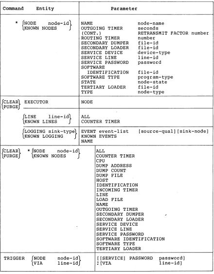
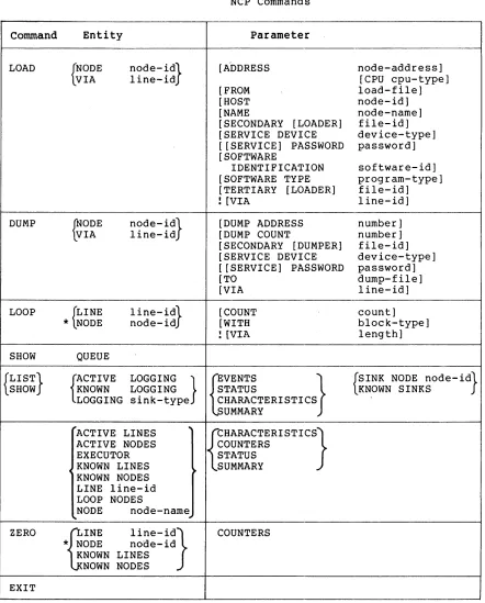
Table I lists the complete set of NCP
commands
specified
in
this
document.
Details concerning options and explanations of each command
follow in the text.
Appendix I lists the NCP commands supporting each
Network Management interface.
Command
Entity
{
SET
DEFINE
}EXECUTOR
{
LINE
KNOWN LINES
line-id}
Table I
NCP Commands
NODE
ALL
CONTROLLER
COST
Parameter
COUNTER TIMER
DUPLEX
NORMAL TIMER
SERVICE
SERVICE TIMER
STATE
TRIBUTARY
TYPE
{
LOGGING sink-type} EVENT event-list
KNOWN LOGGING
KNOWN EVENTS
*
{NODE
nOde-id}
KNOWN NODES
**
Legend:
NAME
STATE
ADDRESS
ALL
.BUFFER SI ZE
COUNTER TIMER
CPU
DELAY FACTOR
DELAY WEIGHT
DUMP ADDRESS
DUMP COUNT
DUMP FILE
HOST
IDENTIFICATION
INACTIVITY TIMER
INCOMING TIMER
LINE
LOAD FILE
MAXIMUM ADDRESS
MAXIMUM BUFFERS
MAXIMUM COST
MAXIMUM HOPS
MAXIMUM LINES
MAXIMUM LINKS
MAXIMUM VISITS
destination-node
controller-mode
cost
seconds
duplex-mode
milliseconds
service-control
milliseconds
line-state
tributary-address
line-type
[source-qual] [sink-node]
sink-name
sink-state
node-address
memory-units
seconds
cpu-type
number
number
number
number
file-id
node-id
id-string
seconds
seconds
line-id
file-id
number
number
number
number
number
number
number
*
EXECUTOR may be substituted for NODE node-ide
**
The node-id with the LINE parameter is a name.
With all other
parameters, it can be either a name or address.
[image:23.613.86.529.108.727.2]Command Entity
*
{NODE node- id} KNOWN NODES{CLEAR} EXECUTOR LPURGE
{LINE KNOWN LINES I ine- id}
Table I (Cont.) NCP Commands
Parameter
NAME
OUTGOING TIMER (CONT. )
ROUTING TIMER SECONDARY DUMPER SECONDARY LOADER SERVICE DEVICE SERVICE LINE SERVICE PASSWORD SOFTWARE
IDENTIFICATION SOFTWARE TYPE STATE
TERTIARY LOADER TYPE
NODE
ALL
COUNTER TIMER
node-name seconds
RETRANSMIT FACTOR number number
file-id file-id device-type line-id password
file-id program-type node-state file-id node-type
{LOGGING sink-type} EVENT event-list KNOWN LOGGING KNOWN EVENTS [source-qual] [sink-node]
{CLEAR} LPURGE
TRIGGER
*
{NODE node- id} LKNOWN NODES{VIA NODE nOde-id} line-id NAME
ALL
COUNTER TIMER CPU
DUMP ADDRESS DUMP COUNT DUMP FILE HOST
IDENTIFICATION INCOMING TIMER LINE
LOAD FILE NAME
OUTGOING TIMER SECONDARY DUMPER SECONDARY LOADER SERVICE DEVICE SERVICE LINE SERVICE PASSWORD
SOFTWARE IDENTIFICATION SOFTWARE TYPE
[image:24.612.78.518.77.640.2]TERTIARY LOADER
[[SERVICE] PASSWORD password]
! [VIA line-id]
Command
Entity
LOAD
{NODE
nOde-id}
VIA
line-id
DUMP
~ODE
nOde-id}
VIA
line-id
LOOP
{LINE
line-id}
*
NODE
node-id
SHOW
QUEUE
{LIST}
rCTIVE
LOGGING
}
SHOW
KNOWN
LOGGING
LOGGING sink-type
"'ACTIVE LINES
~ACTIVE NODES
EXECUTOR
~
KNOWN LINES
~KNOWN NODES
LINE line-id
LOOP NODES
NODE
node-name
~
ZERO
{]INE
line-id}*
NODE
node-idKNOWN LINES
NOWN NODES
EXIT
Table
1(Cont.)
NCP Commands
Parameter
[A'oDRESS
[FROM
[HOST
[NAME
[image:25.612.92.534.68.617.2][SECONDARY [LOADER]
[SERVICE DEVICE
[ [SERVICE] PASSWORD
[SOFTWARE
IDENTIFICATION
[SOFTWARE TYPE
[TERTIARY [LOADER]
![VIA
[DUMP ADDRESS
[DUMP COUNT
[SECONDARY [DUMPER]
[SERVICE DEVICE
[ [SERVICE] PASSWORD
[TO
[VIA
[COUNT
[WITH
![VIA
{jVENTS
STATUS
}
CHARACTERISTICS
UMMARY
{CHARACTERI STICS}
COUNTERS
STATUS
SUMMARY
COUNTERS
node-address]
[CPU cpu-type]
load-file]
node-id]
node-name]
file-id]
device-type]
password]
software-id]
program-type]
file-id]
line-id]
number]
number]
file-id]
device-type]
password]
dump-file]
line-id]
count]
block-type]
length]
{SINK NODE nOde-id}
KNOWN SINKS
The general form of the commands is:
{
SET }
entity parameter DEFINE
Entity is one of the following:
EXECUTOR
LINE line-identification LOGGING sink-type
NODE node-identification KNOWN LINES
KNOWN LOGGING KNOWN NODES
Parameter is one (or more, if allowed by the implementation) of the parameter options defined for the specified entity.
3.3.1.1 SET and DEFINE EXECUTOR NODE destination-node - The SET and DEFINE EXECUTOR NODE commands, processed by NCP, change the executor node for subsequent commands. Access control information may be supplied as described in Section 3.2.4.
3.3.1.2 SET and DEFINE KNOWN Entity Commands - These commands set volatile and permanent parameters for each one of the specified entities known to the system. The format is:
{ SET } KNOWN plural-entity parameter DEFINE
Plural entity is one of LINES, LOGGING or NODES.
The parameters are the same as for the SET and DEFINE entity commands (Sections 3.3.1.3, 3.3.1.4, and 3.3.1.5). However, DEFINE KNOWN plural-entity ALL has no meaning. SET KNOWN plural-entity ALL loads all permanent entity parameters into the volatile data base.
3.3.1.3 SET and DEFINE LINE Commands - These commands and permanent line parameters for the line identified.
set volatile The format is:
{
SET }
LINE line-id DEFINE
,ALL
CONTROLLER COST
COUNTER TIMER DUPLEX
NORMAL TIMER SERVICE
SERVICE TIMER STATE
TRIBUTARY TYPE
controller-mode cost
seconds duplex-mode milliseconds service-control milliseconds line-state
where:
line-id
ALL
Is as specified in Section A.l.
with SET, puts permanent line parameters associated with the line in the volatile data base. With DEFINE, creates a permanent data base entry for one line.
CONTROLLER controller-mode Sets the controller mode for the line.
COST cost
COUNTER TIMER seconds
DUPLEX duplex-mode
NORMAL TIMER milliseconds
The values for controller mode are as follows:
LOOPBACK
NORMAL
This is
controlled controller.
for software loopback of the
This is for normal controller operating mode.
The command automatically turns the line OFF before setting the mode and back to the original state after.
Sets the routing line cost. The cost is a decimal number in the range 1 to 25. The cost parameter is a positive integer value associated with using a line and is used in the Transport routing algorithm (Transport Functional Specification).
Sets a timer whose expiration causes a line counter logging event. Table 7 lists
the line counters. These counters
constitute the data for certain logged events (Table 12). The line counters are recorded as data in the event and then zeroed. Seconds is specified as a decimal number in the range 1-65535.
Sets the hardware duplex mode of the line. The possible modes are:
FULL Full-duplex
HALF Half-duplex
Specifies the maximum amount of time allowed to elapse before a retransmission is necessary. This is used for normal
operation of the line. Timing is
SERVICE service-control Specifies whether or not the service operations (loading, dumping, line loopback testing) are allowed for the line. The service-control values are as follows:
ENABLED
DISABLED
The line may be put into SERVICE state and service functions performed.
The line may not be put into SERVICE state and service
functions may not be
performed.
SERVICE TIMER milliseconds Specifies the maximum amount of time allowed to elapse before a receive request completes while doing service operations on the line. Service operations are down-line load, up-line dump, or line loop testing. The timer value is an integer number in the range 1-65535. This timer applies to the use of the service protocol
(for example, MOP).
STATE line-state Sets the line's operational state at the executor node. The possible states are as follows:
ON The line is available to its owner for normal use, with the exception of temporary overrides for service functions.
OFF The line is not used by any
network or network-related
software. The line is
functionally non-existent.
SERVICE This state applies only to the volatile data base (SET command) . The line is available for active service functions: load, dump, and line loop. The line can provide passive loopback - direct line software-looped testing (Figure 8) - if no active service function is in progress.
CLEARED This state applies only to the permanent data base (DEFINE command). A line in this state has space reserved in system tables but has no other databases or parameters in volatile memory. This state is only applicable in systems that can implement it.
NOTE
An implementation may choose to effect service functions in the ON state, as temporary overrides to normal traffic. In this case, error messages must clearly indicate when a line is in a temporary service condition.
TRIBUTARY tributary-address Sets the physical tributary address of the line. The tributary address is a decimal number in the range 0-255. It reflects
the bit setting of the hardware
switch-pack for the tributary.
TYPE line-type Sets up the line for the data
protocol operation together with DUPLEX option. Line type is one of following:
link the the
POINT For a point to point line CONTROL For a multipoint control
station
TRIBUTARY For a multipoint tributary
3.3.1.4 SET and DEFINE LOGGING Commands - This set of commands is used to control event sinks (where events are logged) and event lists (that control which events get logged). Appendix F specifies events. The command format is:
{
SET }
LOGGING sink-type DEFINE
where:
sink-type
[sink-node]
EVENT event-list KNOWN EVENTS
[source-qual] [sink-node] [source-qual] [sink-node] NAME sink-name
STATE sink-state
Is one of CONSOLE, FILE, or MONITOR. Determines the ultimate sink for events. Section A.2 specifies the sink-type format.
Specifies a node that receives events. is of the form:
SINK NODE node-id or
SINK EXECUTOR
It
[source-qualifier]
EVENT event-list
NAME sink-name
KNOWN EVENTS
STATE sink-state
Selects a specific entity for certain event classes. It has the form:
LINE line-id or NODE node-id
This option can either precede or follow KNOWN EVENTS or EVENT event-list.
Enables the recording of the events specified by the event list. The event list consists of event class.event type(s). The types (Table 12) are specified in ranges using hyphens and in lists using commas. For example:
3.0-2 4.1-4,8,10 5.3-4,9 6.1,3,5
wild card notation indicates all types of events for a particular class. For example:
3.*
Establishes device or file names for sink types CONSOLE and FILE, respectively. It specifies a process identification for a MONITOR.
Enables the recording of all events known to the executor node for the specified sink node.
Controls the operation specified by sink type. values of sink state are:
of the sink The possible
ON The sink is available for receiving events.
OFF The sink is not available and any events destined for i t should be discarded.
HOLD The sink is temporarily unavailable and events should be queued.
The following is an example of the SET LOGGING command:
3.3.1.5 SET and DEFINE NODE Commands - These commands set volatile or permanent parameters for a node. Certain parameters can be set only for the executor node or for adjacent nodes. See Table 9. The format for the command is:
{
SET }
NODE DEFINE
node-id
where:
node-id
ADDRESS node-address
ALL
ADDRESS ALL
BUFFER SIZE COUNTER TIMER CPU
DELAY FACTOR DELAY WEIGHT DUMP ADDRESS DUMP COUNT DUMP FILE HOST
IDENTIFICATION INACTIVITY TIMER INCOMING TIMER LINE
LOAD FILE
MAXIMUM ADDRESS MAXIMUM BUFFERS MAXIMUM COST MAXIMUM HOPS MAXIMUM LINES MAXIMUM LINKS MAXIMUM VISITS NAME
OUTGOING TIMER RETRANSMIT FACTOR ROUTING TIMER SECONDARY DUMPER SECONDARY LOADER SERVICE DEVICE SERVICE LINE SERVICE PASSWORD SOFTWARE
IDENTIFICATION SOFTWARE TYPE STATE
TERTIARY LOADER TYPE node-address memory-units seconds cpu-type number number number number file-id node-id id-string seconds seconds line-id file-id number number number number number number number node-name seconds number seconds file-id file-id device-type line-id password software-id program-type node-state file-id node-type
Specifies node name or node address (Section A.3). In some cases, noted below, the node identification must be a node name. EXECUTOR can be substituted for NODE executor-node-identification.
Sets the address of the executor node. This cannot be used to set the address of any other node.
BUFFER SIZE memory-units
COUNTER TIMER seconds
CPU cpu-type
DELAY FACTOR number
DELAY WEIGHT number
DUMP ADDRESS number
DUMP COUNT number
DUMP FILE file-id
Sets the size of the line buffers. The size is a decimal integer in the range 1-65535. This size is in memory units (Appendix C). It is the actual buffer size and therefore must take into account such things as protocol overhead. There is one buffer size for all lines.
Sets a timer whose expiration causes a node counter logging event. Node counters are listed in Table 10. They constitute data for certain logged events (Table 12). The node counters will be recorded as data in the event and then zeroed. Seconds is specified as a decimal number in the range 1-65535.
Sets the default target node CPU type for down-line loading the adjacent node. The possible values are:
PDP 8 PDP 11
DECSYSTEM 10 DECSYSTEM 20 VAX
Sets the number by which to multiply one sixteenth of the estimated round trip delay to a node to set the retransmission timer to that node. The round trip delay is used in an NSP algorithm that determines when to retransmit a message (NSP functional specification) . The number is decimal in the range 1-255.
Sets the weight to apply to a current round trip delay estimate to a remote node when updating the estimated round trip delay to a node. The number is decimal in the range 1-255. On some systems the number must be 1 less than a power of 2
for computational efficiency (NSP
functional specification).
Sets the address in memory to begin an up-line dump of the adjacent node.
Determines the default number of memory units to up-line dump from the adjacent node.
HOST node-id
. IDENTIFICATION id-string
INACTIVITY TIMER seconds
INCOMING TIMER seconds
LINE line-id
LOAD FILE file-id
MAXIMUM ADDRESS number
MAXIMUM BUFFERS number
Sets the identification of the host node. For the executor, this is the node from which it requests services. For an adjacent node, it is a parameter that the adjacent node receives when it is
down-line loaded. If no host is
specified, the default is executor node .
Sets the text identification string for the executor node (for example, II Research
Lab"). The identification string is an arbitrary string of 1-32 characters. If the string contains blanks or tabs it must be enclosed in quotation marks ("). A quotation mark within a quoted string is indicated by two adjacent quotation marks
(
....
).
Sets the maximum duration of inactivity (no data in either direction) on a logical link before the node checks to see if the logical link still works. If no activity occurs within the maximum number of seconds, NSP generates artificial traffic
to test the link (NSP functional
specification). The range is 1-65535.
Sets the maximum duration between the time a connect is received for a process and the time that process accepts or rejects it. If the connect is not accepted or rejected by the user within the number of seconds specified, Session Control rejects it for the user. The range is 1-65535.
Defines a loop node and sets the identification of the line to be used for all traffic from the node. Loop node identification must be a node name. No line can be associated with more than one node name.
Sets the identification of the file to read from when the node is down-line loaded. The file identification is a string that is interpreted depending on the file system of the executor.
Sets the largest node address and, therefore, number of nodes that can be known about. The number is an integer in the range 1-65535.
MAXIMUM COST number
MAXIMUM HOPS number
MAXIMUM LINES number
MAXIMUM LINKS number
MAXIMUM VISITS number
NAME node-name
OUTGOING TIMER seconds
RETRANSMIT FACTOR number
ROUTING TIMER seconds
SECONDARY DUMPER file-id
Sets the maximum total path cost allowed from the executor to any node. The path cost is the sum of the line costs along a path between two nodes (Transport functional specification). The maximum is a decimal number in the range 1-1023.
Sets the maximum routing hops from the node to any other reachable node. A hop is the logical distance over a line between two adjacent nodes (Transport functional specification). The maximum is a decimal number in the range 1-31.
Sets the maximum number of lines that this node can know about. The number is a decimal in the range 1-65535.
Sets the maximum active logical link count for the node. The count is a decimal number in the range 1-65535.
Sets the maximum number of nodes a message coming into this node can have visited. If the message is not for this node and the MAXIMUM VISITS number is exceeded, the message is discarded. The number is a decimal in the range MAXIMUM HOPS to 255.
Sets the node name to be associated with the node identification. Only one name can be assigned to a node address or a line identification. No name can be used more than once in the node.
Sets a time-out value for the duration between the time a connect is requested and the time that connect is acknowledged by the destination node. If the connect is not acknowledged within the number of seconds specified, Session Control returns an error. The range is 1-65535.
Sets the maximum number of times the source NSP will restart the retransmission timer when it expires. If the number is exceeded, Session Control disconnects the logical link for the user (NSP functional specification) . The number is decimal in the range 1-65535.
Sets the maximum duration before a routing update is forced. The routing update produces a routing message for an adjacent node (Transport functional specification). Seconds is a decimal integer in the range 1-65535.
SECONDARY LOADER file-id Sets the identification of the secondary loader file, for down-line loading the adjacent node.
SERVICE DEVICE device-type Sets the service device type that the adjacent node uses for service functions when in service slave mode (see Section 4.1.4.2). The device type is one of the standard line device mnemonics.
SERVICE LINE line-id Establishes the line to the adjacent node for down-line loading and up-line dumping. Sets the default if the VIA parameter of either the LOAD or DUMP commands is omitted. When down line loading a node (Section 3.3.4), the node identification must be that of the target node.
SERVICE PASSWORD password Sets the password required to trigger the bootstrap mechanism on the adjacent node. The password is a hexadecimal number in the range 0-FFFFFFFFFFFFFFFF (64 bits).
SOFTWARE IDENTIFICATION Sets the identification of the software
software-id that is to be loaded when the adjacent
node is down-line loaded. Software-id contains up to 16 alphanumeric characters.
SOFTWARE TYPE program-type Sets the initial target node software program type for down-line loading the adjacent node. Program type is one of:
STATE node-state
TERTIARY LOADER file-id
SECONDARY [LOADER] TERTIARY [LOADER] SYSTEM
Sets the operational state of the executor node. The possible states are:
ON
OFF
SHUT
RESTRICTED
Allows logical links.
Allows no
terminates and stops through.
new existing routing
links, links, traffic
Allows no new logical links, does not destroy existing logical links, and goes to the OFF state when all logical links are gone.
Allows logical nodes.
no new incoming
links from other
TYPE nOde-type Sets the type of the node as one of the following:
ROUTING Full routing node.
NONROUTING Node with no routing
capability.
PHASE II Phase II node.
3.3.2 CLEAR and PURGE Commands - These commands clear parameters from the volatile and permanent data bases. The CLEAR command affects the volatile data base; the PURGE command affects the permanent data base. Not all parameters can be cleared individually. A cleared or purged parameter or entity identification is the same as one that has not been set or defined. The general form of the command is:
{
CLEAR}
entity parameter PURGE
The entities are the same as for the SET and DEFINE commands (Section 3.3.1) .
3.3.2.1 CLEAR and PURGE EXECUTOR NODE Commands - The CLEAR EXECUTOR NODE command resets the executor to the node on which NCP is running. Note that CLEAR EXECUTOR does not return the executor to that defined in the permanent data base. The PURGE EXECUTOR NODE command redefines the executor in the permanent data base as the local node. Access control is reset as well.
3.3.2.2 CLEAR and PURGE KNOWN Entity Commands - These commands clear and purge parameters for all of the specified entity known to the system. The format of the command is:
{ CLEAR} KNOWN plural-entity parameter PURGE
Plural entity is one of LINES, LOGGING or NODES.
Parameter is one or possibly more of the parameters associated with the CLEAR and PURGE entity commands (Sections 3.3.2.3, 3.3.2.4, and 3.3.2.5) .
3.3.2.3 CLEAR and PURGE LINE Commands - These commands parameters from the volatile and permanent data bases. format is:
{ CLEAR} LINE 1 ine-id PURGE
ALL
COUNTER TIMER
where:
ALL
COUNTER TIMER
Clears all parameters associated with the
line identified and the line
identification itself from the volatile or permanent data base.
Clears the timer that controls the periodic logging of the line's counters. This implies that they are no longer to be logged.
3.3.2.4 CLEAR and PURGE LOGGING Commands - These commands, in conjunction with the SET and DEFINE LOGGING commands, control event sinks and event lists. The same general definitions (sink-node, sink-type, and source-qualifier) that apply to the SET LOGGING command
(Section 3.3.1.4) apply here.
{ CLEAR} LOGGING sink-type PURGE
where:
EVENT event-list
NAME
KNOWN EVENTS
EVENT event-list [source-qual] [sink-node] KNOWN EVENTS [source-qual] [sink-node] NAME
Disables the recording of the events
specified by the event list
(event-class.event-type) . Appendix F specifies events. Section 3.3.1.4 details the format of the event list. The sink node option turns off events for the specified sink node. If no sink node is specified, the EXECUTOR is assumed.
Clears the sink name assigned to the sink type. The sink then becomes the default for the specific system, either no sink or some system-specific standard.
Disables the recording of all events known to the executor node for the sink node.
3.3.2.5 CLEAR and PURGE NODE Commands - These commands clear volatile (using CLEAR) or permanent (using PURGE) parameters for the node. Node identification can be either a node name or a node address, except for the LINE option where it must be a name. EXECUTOR may substitute for NODE executor-node-identification.
{
CLEAR}
NODE node-id PURGE
ALL
COUNTER TIMER CPU
DUMP ADDRESS DUMP COUNT DUMP FILE HOST
IDENTIFICATION INCOMING TIMER LINE