© 2016, IRJET | Impact Factor value: 4.45 | ISO 9001:2008 Certified Journal | Page 298
FFT Based ECG Analyser Using Modified Booth Algorithm
Suresh Narasimman
1, Vanitha Muthaiah
21
st Assistant Professor,
2M.E Student,
Department of Electronics and Communication Engineering
Prathyusha Engineering College, Tamil Nadu, India
---***---Abstract -
Cardiac vascular is a disease which plays a highrisk factor in the world, where many people leads to death due to sudden cardiac arrest. Doctor uses several test to detect the factors that put people at high risk of Sudden Cardiac Attack like Echocardiography (ECG), Multi Gated Acquisition Scan
(MUGA) Test or Cardiac Magnetic Resonance Imaging(MRI), Cardiac Catheterization, and Blood Test which all are in off line analysis of cardiac patient but recently proposed the method of real time Cardiac monitoring system which is used to analyze the abnormality of the ECG signal using Fast Fourier Transform (FFT) and send comments to the receiver using short message service(SMS) through Global System Mobile(GSM), where the Fast Fourier Transform (FFT) used in this has more delay, which takes much time in computation due to the presence of multiplier in it. Thus to increase the speed of FFT the modified booth algorithm is proposed here, in which the number of slice, number of 4-input LUTs and number of bonded IOB gets reduced when compare to the other existing FFT speed increment algorithm, which is further implement in that recently proposed method of ECG analyzer and the output will be compared to find the efficiency.
Key Words: Ecocardiograph, fast fourier transform, short
message service, global system mobile, vedic mathematics, compressor.1.INTRODUCTION
Heart failure is the significant issue in the body. Heart failure, otherwise called cardiopulmonary capture or circulatory capture, is a sudden stop in compelling blood flow because of the disappointment of the heart to contract adequately. Heart rate can be measured by utilizing the ECG, where the PQRST waveform happened by cadence which is utilized to investigation the typical and variation from the norm of the heart rate. The progressions in pumping of heart causes an adjustments in cadence of PQRST wave called arrthymia. Heart failure happen in division of second which may not be distinguish effectively. In this way quiet checking is utilized to screen the patient parameters.
Figure- 1: Block Diagram Of Cardiac Monitoring System
1.1 System Description
Simple constant ECG sign is acquired from the patient by utilizing ECG sensor module. The ECG sign is pre-intensified and given to a SOC based design for analyzing the heart failure. this is appeared in fig 1. the depiction of the capacity of cardiovascular monitoring framework is as per the following:
ECG signal generation: The primary point of ecg record the electrical movement of the heart.the ECG wave produces little electrical heartbeats that are given to a pre-amplifier. these exercises are measured utilizing three terminals module.
Pre-processing Block: The feeble signs are prepared by the pre-enhancement process utilizing a pre-handling square. Since the outlined SOC engineering is isolated from the pre-preparing block, it does not permit the clamor sign to the primary design. kalman separating is utilized to decrease obstruction commotion and the FFT signal examination is performed. simple and advanced channel are utilized for support of sign quality.
Result Notification: Amid heart failure, the doctor ought to know about the warning in ceaseless checking framework. The design comprises of two strategies for warning in particular, visual notice and SMS caution. An oscilloscope is utilized, empowering the procurement to take note of the wave example of direct recorded sign. Some of the time the specialist will be unable to watch the screen consistently. Thus a ready caution is intended to empower the specialist to change the volume of alert with the end goal of hearing. In the second strategy, SMS is sent to the specialist's versatile when cardiovascular indications emerge furthermore store the sign for future reference utilizing secure advanced (SD) card
1.2 Need For Study
Here the ECG sign is gained by kalman channel which will predefined the waveform, then the ordinxary and irregularity of the waveform will be anticipated by the FIR channel and send this outcome through the GSM.The velocity of the processor is relying upon multiplier, where delay happens in advanced preparing which will lessen the pace and builds the force utilization. Fast multipliers and rapid
Preprocessing
proprocessing
Ecg
sigs
sigs
ign
alsi
gna
l
Kalman filter
© 2016, IRJET | Impact Factor value: 4.45 | ISO 9001:2008 Certified Journal | Page 299 adders are required to accelerate the FFT. The velocity of the
FFT can be expanded by utilizing the different technique. Here the altered corner calculation is utilized to accelerate
.
1.3
Objective Of Study
Various types of algorithm is available to increase the FFT speed which helps to acquire the ECG at high speed, thus the acquired data can be send in same aspect.The various types of algorithms are Vedic mathematics, Booth algorithm, Modified booth algorithm
Vedic science has 16 sutras and 13 sub sutras where every sutras has distinctive operation. Among the 16 sutras nikilam and urthras are material for the increase reason. In this way vedic augmentation is utilized to build the pace of the duplication by lessening the quantity of halfway product. Booth calculation expand the rate of the increase by decreasing the progressions of it. In this way it finished up radix 8 is higher rate than radix 2 and radix 4.Now here the changed stall calculation executed here to accelerate the quick fourier change and the proficiency is contrasted and the current strategy.
2.
EXISTING METHOD
In existing strategy vedic multiplier is utilized to expand the rate of the FFT. Among the 16 sutras in vedic science nikilam sutra and urdhwa sutra is pertinent to perform multiplier.
2.1 Urdhva-Tiryakbyham Sutra
Figure- 2: Urdhva-Tiryakbyham Sutra
The importance of this sutra is "vertically and across "and it is relevant to all the increase operation. This method is known as exhibit duplication procedure. It is a proficient duplication system when the multiplier and multiplicand lengths are little, however for the bigger length augmentation this strategy is not pertinent. To beat this issue it has been portray nikilam sutra for computing the augmentation of two vast numbers.[1]
2.2 Nikilam Navatascaramam Sutra
Urdhva sutras is material just when the length of the multiplier and multiplicand are little, where the more drawn out multiplicand and multiplier nikilam navatscaramam sutra is utilized because of the propogation of convey.
2.3
Disadvantage
Performance degradation is more timing waste.
High power consumption.
Takes more number of slices.
3. PROPOSED SYSTEM
3.1 Introduction:
In proposed framework a maturing mindful solid multiplier outline with novel versatile hold rationale (AHL) circuit. The multiplier in view of the Variable-idleness pipelined multiplier engineering with an altered corner radix-4 calculation. The AHL circuit to accomplish dependable operation affected by the NBIT and PBIT impacts. Our proposed engineering with the 16x16 changed stall multipliers.
3.2.Proposed Technique
Variable-inactivity pipelined multiplier engineering with an modified booth algorithm
3.
3 Modified Booth algorithm
Multiplication comprises of three stages:
1) The initial step to create the incomplete items
2) The second means to include the created incomplete items until the last two lines are remained
3) The third means to process the last duplication results by including the last two lines.
© 2016, IRJET | Impact Factor value: 4.45 | ISO 9001:2008 Certified Journal | Page 300 is known as the most proficient Booth encoding and
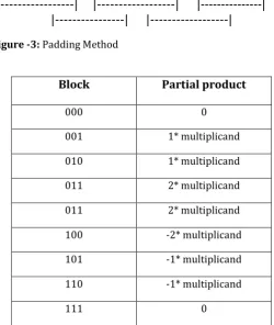
unraveling plan. To duplicate X by Y utilizing the altered Booth calculation begins from gathering Y by three bits and encoding into one of {-2, - 1, 0, 1, 2}. Table I demonstrates the standards to produce the encoded signals by MBE plan and the comparing rationale graph. The Booth decoder creates the incomplete items utilizing the encoded signals.
3.4
Architecture of the Modified Booth Multiplier
Design of the normally utilized changed Booth multiplier. The inputs of the multiplier are multiplicand X and multiplier Y. The Booth encoder encodes information Y and infers the encoded signals. The Booth decoder creates the incomplete items as indicated by the rationale chart in utilizing the encoded signals and the other info X. The Wallace tree registers the last two lines by including the created halfway items. The last two columns are added to create the last augmentation results utilizing the convey look-ahead viper (CLA).
By and large, we perform numerous numerical operations in our every day life, for example, expansion, subtraction, augmentation, division, et cetera. Give us a chance to consider the duplication handle that can be performed in various strategies. Distinctive sorts of calculations can be utilized to perform duplication like framework increase technique, long augmentation, cross section duplication, laborer or double increase, et cetera. Parallel increase is typically performed in computerized hardware by utilizing an electronic circuit called as paired multiplier. These parallel multipliers are actualized utilizing distinctive PC number-crunching systems. Stall multiplier that works in view of corner calculation is a standout amongst the most every now and again utilized double multipliers.
3.5 Algorithm (for signed numbers)
Pad the LSB with one zero.
Pad the MSB with 2 zeros if n is even and 1 zero if n is odd.
Divide the multiplier into covering gatherings of 3-bits.
Determine incomplete item scale element from changed stall 2 encoding table.
Compute the Multiplicand Multipliers.
Sum Partial Products.
[image:3.595.316.567.130.427.2]0
0
0
0
0
1
0
1
0
0
0
|---| |---| |---|
|---| |---|
Figure -3: Padding Method
Block
Partial product
000 0
001 1* multiplicand
010 1* multiplicand
011 2* multiplicand
011 2* multiplicand
100 -2* multiplicand
101 -1* multiplicand
110 -1* multiplicand
111 0
Table -1: Radix-4 Booth Encoding Table
3.6
Fast Fourier Transform:
A quick Fourier change (FFT) calculation figures the discrete Fourier change (DFT) of a grouping, or it's backwards. Fourier investigation changes over a sign from its unique area (frequently time or space) to a representation in the recurrence area and the other way around. A FFT quickly processes such changes by factorizing the DFT grid into a result of meager (for the most part zero) factors.[1] thus, it figures out how to lessen the many-sided quality of registering the DFT from o(n2), which emerges if one essentially applies the meaning of DFT, to O( n log n), where n is the information size.
© 2016, IRJET | Impact Factor value: 4.45 | ISO 9001:2008 Certified Journal | Page 301 The Fast Fourier Transform (FFT) is essentially
a quick (computationally productive) approach to figure the Discrete Fourier Transform (DFT). By making utilization of periodicities in the sine's that are increased to do the changes, the FFT extraordinarily decreases the measure of count required. Here's a little diagram.
Practically, the FFT deteriorates the arrangement of information to be changed into a progression of littler information sets to be changed. At that point, it breaks down those littler sets into considerably littler sets. At every phase of handling, the consequences of the past stage are consolidated in uncommon way.
At long last, it ascertains the DFT of every little information set. For instance, a FFT of size 32 is broken into 2 FFTs with size 16, which are again broken into 4 FFTs with size of 8, which are broken into 8 FFTs (size 4), which are then broken into 16 FFTs of size 2. Ascertaining a DFT of size 2 is insignificant.
Things being what they are it is conceivable to take the DFT of the main N/2 focuses and join them specially with the DFT of the second N/2 focuses to create a solitary N-point DFT. Each of these N/2-point DFTs can be computed utilizing littler DFTs as a part of the same way.
One (radix-2) FFT starts, thusly, by computing N/2-point DFTs. These are joined to shape N/4-point DFTs. The following stage produces N/8-N/4-point DFTs, etc, until a solitary N-point DFT is created.
The DFT takes N^2 operations for N focuses. Since at any stage the calculation required to join littler DFTs into bigger DFTs is relative to N, and there are log2 (N) stages (for radix 2), the aggregate calculation is corresponding to N * log2 (N). Hence, the proportion between a DFT calculation and a FFT calculation for the same N is corresponding to N/log2 (n).
In situations where N is little this proportion is not exceptionally critical, but rather when N turns out to be huge, this proportion gets expansive. (Each time you twofold N, the numerator copies, yet the denominator just increments by 1.)
The most widely recognized and well known FFTs are "radix 2". In any case, different radices are once in a while utilized, which are normally little numbers under 10. For instance, radix-4 is particularly alluring on the grounds that the
"twiddle elements" are every one of the 1, - 1, j, or - j, which can be connected with no duplications by any stretch of the imagination.
"Blended radix" FFTs additionally should be possible on "composite" sizes. For this situation, you separate a non-prime size into its prime variables, and do a FFT whose stages utilize those components.
For instance, a FFT of size 1000 may be done in six stages utilizing radices of 2 and 5, since 1000 = 2 * 2 * 2 * 5 * 5 * 5. It may likewise be done in three stages utilizing radix 10, since 1000 = 10 * 10 * 10.
The "radix" is the extent of FFT deterioration. In the sample over, the radix was 2. For single-radix FFTs, the change size must be a force of the radix. In the case over, the size was 32, which are 2 to the fifth force.
"Twiddle elements" are the coefficients used to consolidate results from a past stage to frame inputs to the following stage.
So as to improve the outline, take note of that the amount WN is characterized as:
WN=e-j2π/N
This prompts the meaning of the twiddle elements as:
WNnk=e-j2πnk/N
The twiddle components are essentially the sine and cosine premise capacities written in polar structure. Note that the 8-point DFT appeared in the graph requires 64 complex duplications. When all is said in done, a N-point DFT requires N2 complex duplications. The quantity of augmentations required is noteworthy on the grounds that the duplication capacity requires a generally vast measure of DSP preparing time. Indeed, the aggregate time required to figure the DFT is straightforwardly corresponding to the quantity of increases in addition to the required measure of overhead.
© 2016, IRJET | Impact Factor value: 4.45 | ISO 9001:2008 Certified Journal | Page 302
3.7 Application
Fourier transforms Discrete cosine transforms Digital filtering
4. RESULT
4.1 Modified Booth Algorithm
METHOD
No
of
slices
No of
4-input
LUTs
No
of
bonded
IOB
Array
258 505 64Urdhva
thiryakbhayam
125 219 64
Nikhilam sutra
162 250 66Booth
99 148 33Table- 2: Comparison Of Multipliers
Figure- 4: Graphical Representation Of Modified Booth Algorithm
4.2 FFT Implemented With Modified Booth
Algorithm
Method
No of slices
No of 4-input
LUTs
Urdhva thiryakbhyam
3610 6139
Nikhilam sutra 3317 5278
Booth 1615 2914
Table- 3: Comparison of FFT
Figure- 5: Graphical Representation Of Modified fft Comparison
5 CONCLUSION
The modified booth algorithm is used in fast fourier transform gives the high efficiency by reducing the number of slices and number of input LUT’s when compared with urdhva and nikilam sutras which comes under the vedic mathematics. As a future work, the modified fft is going to use for ECG signal analysis to acquire the signal of the patient at speed and to transfer to the destination using GSM. And also to compare the speed and accuracy of the modified fft with the existing method.
REFERENCES
[1] Pasuluri bindu swetha, V.J.K.Kishor sonti, Raghavendra
© 2016, IRJET | Impact Factor value: 4.45 | ISO 9001:2008 Certified Journal | Page 303
[2] Poornima M, Shivaraj kumar patil, Shivukumar, Shridhar
KP, Sanjay H, “Implementation of multiplier using vedic algorithm”, international journal of innovative technology and exploring engineering(IJITEE) vol-2,issue-6,may 2013
[3] Ms Rajashri K.Bhongade, Ms. Sharada G. Mungale, Mrs.
Karuna Bogawar “Implementation of vedic complex multiplier for digital signal processing”, international journal of engineering research and application(IJERA), ISSN: 2248-9622, april 2014.
[4] Kaustubh M. Gaikwad, Mahesh S. Chavan “Vedic
mathematics for digital signal processing operations”, international journey of computer application (0975-8887) vol 113- no.18, march 2015.
[5] Swapnil Manohar Mehkarkar, Snehal J. Banarase
“Implementation of high speed FIR filter based on ancient vedic multiplication technique”,international journal of emerging technology and advanced engineering, vol 4, issue 5, may 2014
[6] Sukhmeet kaur, suman and Manpreet Signh Manna,
“Implementation of Modified Booth Algorithm ( Radix 4) and its Comparison with Booth algorithm (Radix- 2)”, advanced in electronics and electrical engineering, ISSN 2231-1297, vol 3, number 6(2013),pp. 683-690.
[7] Deepali Chandel, Gagan Kumawat, Pranay Lahoty, vidhi
Vart Chandrodaya, Shailendra Sharma “Booth Multiplier: Ease Of Multiplication”, international journal of emerging technology and advanced engineering, ISSN 2250-2459, vol 3, mar 2013
[8] Hsin-Lei Lin, Robert C. Chang, Ming-Tsai Chan (2004), “
Design of a Novel Radix-4 Booth Multiplier”, IEEE Asia-Pacific Conference on Circuits and Systems, Vol.2, pp. 837-840.
[9] Sumit Vaidhya, D.R,Dandekar, “performance comparison