International Journal of Emerging Technology and Advanced Engineering
Website: www.ijetae.com (ISSN 2250-2459,ISO 9001:2008 Certified Journal, Volume 3, Issue 8, August 2013)
377
Seismic Response of Vertically Irregular RC Frame with
Stiffness Irregularity at Fourth Floor
Shaikh Abdul Aijaj Abdul Rahman1, Girish Deshmukh2
1
PG Student ME (Structural Engineering) Final Year , Department of Civil Engineering, MGM’s College of Engineering Nanded, Maharashtra.
2Assistant professor in Department of Civil Engineering, MGM’s College of Engineering Nanded, Maharashtra Abstract—Structural engineer's greatest challenge in
today’s scenario is constructing seismic resistant structure. Uncertainties involved and behavior studies are vital for all civil engineering structures. The presence of vertical irregular frame subject to devastating earthquake is matter of concern. The present paper attempts to investigate the proportional distribution of lateral forces evolved through seismic action in each storey level due to changes in stiffness of frame on vertically irregular frame. As per the Bureau of Indian Standard (BIS) 1893:2002(part1) provisions, a G+10 vertically irregular building is modeled as an simplified lump mass model for the analysis with stiffness irregularityat fourth floor. To response parameters like story drift, story deflection and story shear of structure under seismic force under the linear static & dynamic analysis is studied. This analysis shows focuses on the base shear carrying capacity of a structure and performance level of structure under severer zone of India. The result remarks the conclusion that, a building structure with stiffness irregularity provides instability and attracts huge storey shear. A proportionate amount of stiffness is advantageous to control over the storey and base shear. The soft computing tool and commercial software CSI-ETABS (version 9.7) is used for modeling and analysis.
Keywords—Structural Irregularities, Vertical irregularities, Stiffness irregularities, I.S 1893:2002(Part1) Provisions, Base Shear, Storey Drift
I. INTRODUCTION
In the past, several major earthquakes have exposed the shortcomings in buildings, which leads to damage or collapse. It has been found that regular shaped buildings perform better during earthquakes. The structural irregularities cause non-uniform load distribution in various members of a building.
There must be a continuous path for these inertial forces to be carried from the ground to the building weight locations. A gap in this transmission path results in failure of the structure at that location. There have been several studies on the irregularities, viz., (Jack P. Moehle, A. M. ASCE 2002), Seismic Response of Vertically Irregular Structures, seismic response of vertically irregular frames with pushover analysis (Chintanapakdee, Chopra, 2004) and evaluation of mass, strength and stiffness limits for regular buildings specified by UBC (Valmundsson and Nau, 1997), Seismic Response of RC Frame Buildings with Soft First Storeys (Arlekar Jaswant N, Jain Sudhir K. and Murty C.V.R, 1997) etc. In the present paper, response of a G+ 10-storeyed vertically irregular frame to lateral loads is studied for stiffness irregularity at fourth floor in the elevation. These irregularities are introduced by changing the properties of the members of the storey under consideration maintaining aspect ratio for vertically irregular frame Specified in I.S 1893:2002(part1) Guidelines. Stiffness irregularities include the height of the column increased on the fourth floor which is applied on vertically irregular frame. Effects on storey-shear forces, storey drifts and deflection of beams is studied.
II.STRUCTURAL IRREGULARITIES
International Journal of Emerging Technology and Advanced Engineering
Website: www.ijetae.com (ISSN 2250-2459,ISO 9001:2008 Certified Journal, Volume 3, Issue 8, August 2013)
[image:2.612.61.550.160.259.2]378
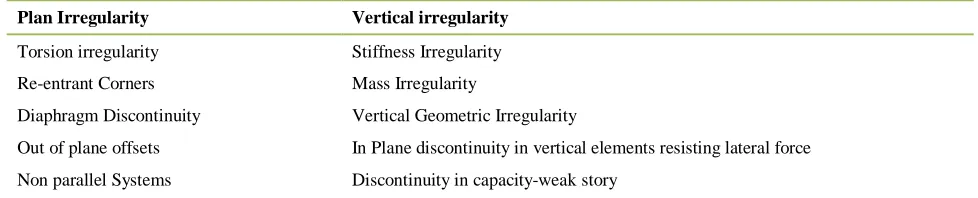
Table 1 Types of Irregularity
Plan Irregularity Vertical irregularity
Torsion irregularity Stiffness Irregularity
Re-entrant Corners Mass Irregularity
Diaphragm Discontinuity Vertical Geometric Irregularity
Out of plane offsets In Plane discontinuity in vertical elements resisting lateral force
Non parallel Systems Discontinuity in capacity-weak story
1. Stiffness Irregularity
Soft storey— A soft storey is one in which the lateral stiffness is less than 70% of that in the storey above or less than 80% of the average lateral stiffness of the three storeys above.
Extreme Soft Storey— An extreme soft storey is one in which the lateral stiffness is less than 60% of that in the storey above or less than 70% of the average stiffness of the three storeys above. For example, buildings on stilts will fall under this category.
2. Mass Irregularity
Mass irregularities are considered to exist where the effective mass of any storey is more than 150% of effective mass of an adjacent storey. The effective mass is the real mass consisting of the dead weight of the floor plus the actual weight of partition and equipment. Excess mass can lead to increase in lateral inertial forces, reduced ductility of vertical load resisting elements, and increased tendency towards collapse due to P-Δ effect. Irregularities of mass distribution in vertical and horizontal planes can result in irregular response and complex dynamics. The central force of gravity is shifted above the base in the case of heavy masses in upper floors resulting in large bending moments.
3. Vertical Geometric Irregularity
Geometric irregularity exists, when the horizontal dimension of the lateral force resisting system in any storey is more than 150% of that in an adjacent storey. The setback can also be visualized as a vertical re-entrant corner. The general solution of a setback problem is the total seismic separation in plan through separation section, so that the portion of building is free to vibrate independently.
4.Discontinuity in capacity - Weak Storey
A weak storey is one in which the storey lateral strength is less than 80% of that in the storey above, the storey lateral strength is the total strength of all seismic force resisting elements sharing the storey shear in the considered direction.
III. PROBLEM FORMULATION
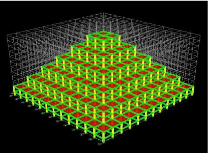
The problem considered for the current study is taken in reference to IS 1893-part 1: 2002 and worked done by Valmundsson and Nau, 1997. This G+10 vertically irregular frame is considered with stiffness irregularity. Two frames including the base frame is referred. Two frames have been analyzed using equivalent static method of IS 1893-part 1: 2002 assuming Preliminary data as Location of Structure in seismic zone V, with soil type medium soil , effective damping 5% and importance factor 1.5. Analysis has been carried out using ETABS V 9.7 program. Configuration of frames is as given below and typical layout is shown in Fig.1.
Frame-1: This is the base model frame of structure with geometrically vertical irregularities and having ten bays and G+10 storeys, with a storey height of 3.5 m for ground floor and 3.0 m for remaining floor and the bay width of 5 m. The basic specifications of the building are: Dimensions of the beam = 0.3 m × 0.6 m; Column size = 0.70 m × 0.30 m; Beam length = 5 m; Column length = 3.5 m; Load combinations as per clause 6.3.1.2 of IS 1893:2002 (Part-1) are;
a) 1.5 (DL+ LL), b) 1.2 (DL + LL ± EQL), c) 1.5 (DL ± EQL), d) 0.9 DL ± 1.5 EQL.
International Journal of Emerging Technology and Advanced Engineering
Website: www.ijetae.com (ISSN 2250-2459,ISO 9001:2008 Certified Journal, Volume 3, Issue 8, August 2013)
379
The base model having the shape irregular to know the effect of stiffness irregularity on the shape (vertical geometric) irregular building the excess height of column at fourth floor as per the IS 1893:2002 ( part-1). The structural data is same except of the following with respect to the base model.
1.Floor height : 5 m
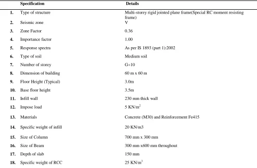
[image:3.612.42.571.234.579.2]The respective change is incorporated on the fourth storey. In reference to this condition following structural & seismic data for modeling the plan, elevation & 3-D view of the base model is included as shown in Table 2.
Table 2 Details of Base Model
Specification Details
1. Type of structure Multi-storey rigid jointed plane frame(Special RC moment resisting
frame)
2. Seismic zone V
3. Zone Factor 0.36
4. Importance factor 1.00
5. Response spectra As per IS 1893 (part 1):2002
6. Type of soil Medium soil
7. Number of storey G+10
8. Dimension of building 60 m x 60 m
9. Floor Height (Typical) 3.0m
10. Base floor height 3.5m
11. Infill wall 230 mm thick wall
12. Impose load 5 KN/m2
13. Materials Concrete (M30) and Reinforcement Fe415
14. Specific weight of infill 20 KN/m3
15. Size of Column 700 mm x 300 mm
16. Size of Beam 300 mm x600 mm throughout
17. Depth of slab 150 mm
International Journal of Emerging Technology and Advanced Engineering
Website: www.ijetae.com (ISSN 2250-2459,ISO 9001:2008 Certified Journal, Volume 3, Issue 8, August 2013)
[image:4.612.103.516.134.435.2]380
International Journal of Emerging Technology and Advanced Engineering
Website: www.ijetae.com (ISSN 2250-2459,ISO 9001:2008 Certified Journal, Volume 3, Issue 8, August 2013)
[image:5.612.95.522.132.431.2]381
Fig 2: frame-2 3-D view Stiffness Irregularity at 4th floor
[image:5.612.63.536.465.705.2]International Journal of Emerging Technology and Advanced Engineering
Website: www.ijetae.com (ISSN 2250-2459,ISO 9001:2008 Certified Journal, Volume 3, Issue 8, August 2013)
382
IV. ANALYSIS RESULTS
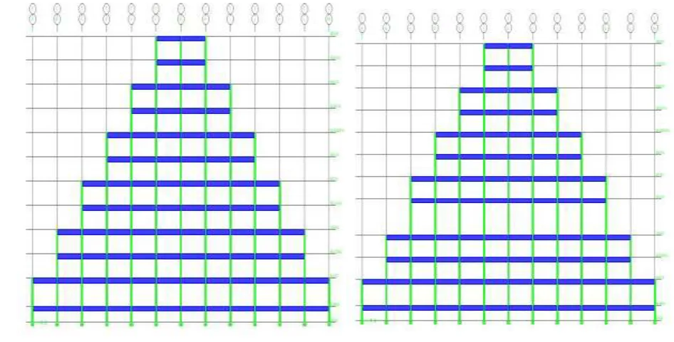
Two frames have been analyzed and responses like lateral storey-displacements, storey drifts and base shears have been computed to study the effects of stiffness irregularity on the vertically irregular frame. The results are presented and discussed hereafter. Table-3 shows displacement of storeys of various frames in X-direction (horizontal) graphically presented in figure
It can be seen that from table-3 the frame-2 gets slightly displaced the more since the lateral stiffness with reference to frame-1 and the bottom two storeys is quite less than other storeys. Whereas its being minimum being in the base frame. Typical deflected shapes of two various frames in combinations is represented in Fig. 4.
TABLE-3
Story Displacement (UX) In X-Direction (MM)
STORY FRAME-1 FRAME -2
Ux Ux
ROOF 0.092815 0.118881
TENTH 0.089327 0.115687
NINTH 0.082156 0.109095
EIGHTH 0.074495 0.101981
SEVENTH 0.063778 0.091971
SIXTH 0.054715 0.083409
FIFTH 0.043792 0.07295
FOURTH 0.03501 0.063706
THIRD 0.025377 0.026005
SECOND 0.01786 0.017976
FIRST 0.010113 0.010136
PLINTH 0.001783 0.001786
International Journal of Emerging Technology and Advanced Engineering
Website: www.ijetae.com (ISSN 2250-2459,ISO 9001:2008 Certified Journal, Volume 3, Issue 8, August 2013)
[image:7.612.48.517.132.405.2]383
Figure 4: Deflected shapes of frames in their combination
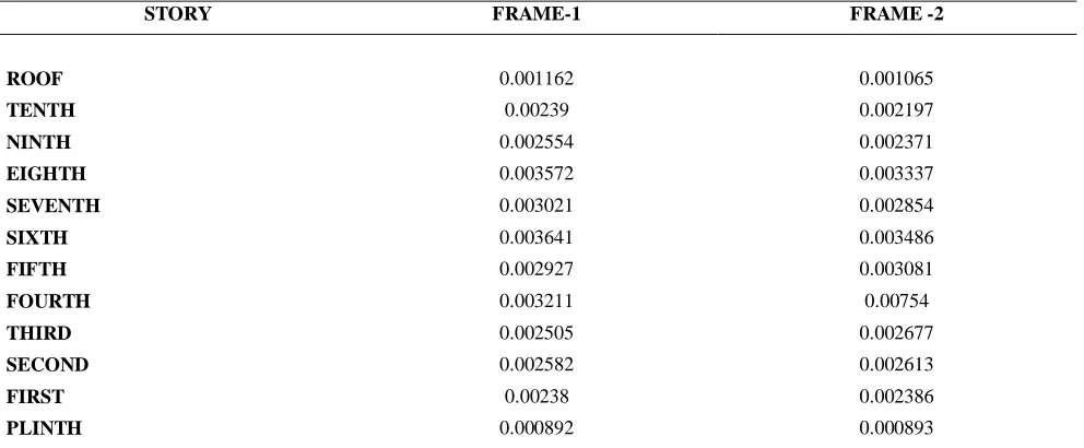
Table 4
Story Drift In X-Direction (MM)
STORY FRAME-1 FRAME -2
ROOF 0.001162 0.001065
TENTH 0.00239 0.002197
NINTH 0.002554 0.002371
EIGHTH 0.003572 0.003337
SEVENTH 0.003021 0.002854
SIXTH 0.003641 0.003486
FIFTH 0.002927 0.003081
FOURTH 0.003211 0.00754
THIRD 0.002505 0.002677
SECOND 0.002582 0.002613
FIRST 0.00238 0.002386
PLINTH 0.000892 0.000893
Storey-drifts for all the frames are tabulated Table-4 while graphically presented in Fig. 3(b).
[image:7.612.61.557.451.656.2]International Journal of Emerging Technology and Advanced Engineering
Website: www.ijetae.com (ISSN 2250-2459,ISO 9001:2008 Certified Journal, Volume 3, Issue 8, August 2013)
384
The storey shears as given by ETABS using IS 1893 part-1: 2002, are Tabulated in Table-5 and represented in Fig. 3(c).
[image:8.612.66.549.213.423.2]Frame-2, being the slightly heaviest one, develops considerable amount of shear force in its storey’s compare to Frames 1.
Table 5
Story Shear In X-Direction (MM)
STORY FRAME-1 FRAME -2
Vx Vx
ROOF -279.8094 -255.0791
TENTH -766.9844 808.7402
NINTH -2121.592 -1965.4
EIGHTH -3283.746 -3063.568
SEVENTH -5146.129 -4855.083
SIXTH -6625.345 -6310.863
FIFTH -8427.288 -8138.716
FOURTH -9705.725 -10057.51
THIRD -10908.04 -11128.14
SECOND -11582.64 -11679.27
FIRST -11981.04 -12004.68
PLINTH -12016.64 -12031.73
[image:8.612.67.547.351.691.2]DISPLACEMENT (MM) STORY DRIFT (MM) STORY SHEAR (MM)
International Journal of Emerging Technology and Advanced Engineering
Website: www.ijetae.com (ISSN 2250-2459,ISO 9001:2008 Certified Journal, Volume 3, Issue 8, August 2013)
385
V. DISCUSSION AND CONCLUSION
Considering the storey displacement, the frame with excess height of 4th floor (frame-2) is the weakest than the (frame-1), as it suffers the considerable change in displacement in all the floors. As far as storey drift is concerned, frame2 is weak than the frame1, as the frame -2 having the suddenly extreme change at fourth floor in story drift. Story shear is slightly more in frame-2. From this it is clear that the frame having stiffness irregularity on vertically irregular frame is susceptible to damage in earthquake prone zone.
In this paper, two frames having different irregularities but with same dimensions have been analyzed to study their behavior when subjected to lateral loads. All the frames were analyzed with the same method as stated in IS 1893-part-1: 2002.
The frame-1 (vertically irregular) develops least storey drifts while the building with stiffness irregularity on vertically irregular building (frame-1) shows maximum storey drift on the respective storey levels.
Hence, this is the most vulnerable to damages under this kind of loading and the same frame with excess height of story develops slightly more storey shears, which should be accounted for in design of columns suitably.
The analysis proves that vertically irregular structures are harmful and the effect of stiffness irregularity on the vertically irregular structure is also dangerous in seismic zone. Therefore, as far as possible irregularities in a building must be avoided. But, if irregularities have to be introduced for any reason, they must be designed properly following the conditions of IS 1893-part-1: 2002 and IS- 456: 2000, and joints should be made ductile as per IS 13920:1993.
Now a day, complex shaped buildings are getting popular, but they carry a risk of sustaining damages during earthquakes. Therefore, such buildings should be designed properly taking care of their dynamic behavior.
REFERENCES
[1] Jack P. Moehle, A. M. ASCE (1984), “Seismic Response Of
Vertically Irregular Structures”, ASCE Journal of Structural Engineering, Vol. 110, No. 9.
[2] Valmundsson and Nau. (1997),“Seismic response of buildings
frames with vertical structuralIrregularities”, ASCE Journal of Structural Engineering, Vol. 123, No. 1, 30-41.
[3] Arlekar Jaswant N, Jain Sudhir K. and Murty C.V.R, (1997),
“Seismic Response of RC Frame Buildings with Soft First Storeys”. Proceedings of the CBRI Golden Jubilee Conference on Natural Hazards in Urban Habitat, New Delhi.
[4] Chintanapakdee and Chopra. (2004), “Seismic response of vertically
irregular frames: response history and modal pushover analyses”, ASCE Journal of Structural Engineering, Vol. 130, No. 8, 1177-1185.
[5] Vinod K. Sadashiva, Gregory A. MacRae& Bruce L. Deam (2009),
“Determination Of Structural Irregularity Limits – Mass Irregularity Example” Bulletin Of The New Zealand Society For Earthquake Engineering, Vol. 42, No. 4.
[6] Ravikumar C M, Babu Narayan K S, Sujith B V, Venkat Reddy D
(2012) , “ Effect of Irregular Configurations on Seismic Vulnerability of RC Buildings” Architecture Research 2012, 2(3): 20-26, Surathkal, India.
[7] IS: 456-2000 (Fourth Revision) , “Indian standard code for practice
for plain reinforced concrete for general building construction”, Bureau of Indian Standards, New Delhi.
[8] C.V.R. Murty, “Earth quake tips”, Indian Institute of Technology