International Journal of Emerging Technology and Advanced Engineering
Website: www.ijetae.com (ISSN 2250-2459, ISO 9001:2008 Certified Journal, Volume 6, Issue 2, February 2016)
151
An Optimized Slot Loaded Frequency Reconfigurable
Antenna with RF-PIN Diode Switch for SDR and CR Based
WLAN Application
Sharanagouda N Patil
1, P.V. Hunagund
2, R.M.Vani
31Research Student (PT), Dept. of Applied Electronics, Gulbarga University, Gulbarga, Karnataka, India 2
Dept. of Applied Electronics, Gulbarga University, Gulbarga, Karnataka, India
3
University Science Instrumentation Center (USIC), Gulbarga University, Gulbarga, Karnataka, India
Abstract— New technologies in communications electronics, such as software-defined radio (SDR) and RF switches implemented using micro-electromechanical systems (MEMS), present new challenges and opportunities for antenna design. In sharp contrast to digital technology where Moore’s law reigns, a fundamental law of physics constrains the ability to realize electrically small antennas that are both efficient and broadband. Software defined radio is defined as a radio in which some or all of their functions are software defined. A Radio is a device that can transmit or receive signals in the radio frequency (RF). The use of software defined radio (SDR) to make communications has enabled the design of intelligent radios called as Cognitive radios, by making communications reconfigurable at lower layers of the networking stack. The major challenge is to design small antennas which can be operated at number of frequency bands. By tuning/switching the resonant frequency, single antenna can operate at different band of frequencies.
Keywords— CR, Primary User, SDR, Secondary User, Spectrum Hole
I. INTRODUCTION
The Software defined radio system is a radio communication system, where the base band processing such as modulation/Demodulation,Source Coding/Decoding etc will be done in the software layer. A truly designed software defined radio (SDR) must support reconfigurability of RF parameters such as frequency, polarization, power, and power gain at RF end. Hence the antenna has to be designed to operate in the multiple radio frequency bands . Reconfigurable antenna is an important functional block in adaptive wireless communication systems such as Cognitive Radio technologies based IEEE 802.22 standard.Thus, a cognitive radio should be able to recognize/sense the spectrum availability and reconfigure itself for more efficient communications and spectrum use [1].
The monitoring of the wireless spectrum is the key in cognitive radio since the spectrum can be idle for90% of the time. Therefore, we should differentiate in such system between a primary user that owns the spectrum and a secondary user that wants to access the spectrum whenever it is idle [2].
In [3], a new technique is introduced which uses a tunable narrowband Planar Inverted-F Antenna (PIFA). In [4], two reconfigurable antenna systems both capable of operating in five cellular radio bands are presented. Both approaches yield overall improvements in performance and are likely to be used in cognitive radios. The proposed reconfigurable antenna is optimized to operate in 2.4GHz and 5.8 GHz frequency band for an SDR or Cognitive Radio based on IEEE 802.11 standard application where both frequency bands can be chosen to operate depending on the interface mode for WLAN.
Multi-mode, multi-band operation presents a formidable challenge to mobile phone designers, particularly for the RF parts. Of these, the antennas occupy the largest volume and, hence, have the biggest impact on the - commercially crucial - styling of the device. It is well-known that antenna bandwidth is proportional to volume. However, the space allocated to the antenna(s) is not increasing: on the contrary, it is tending to decrease due to the demand for thinner, more highly stylized devices. To alleviate this problem, reconfigurable antennas have been proposed that are consistent with a general move towards Software Defined Radios (SDRs): radios that can change parameters - such as the operating band - in an optimal way, using software control that is invisible to the end user.
International Journal of Emerging Technology and Advanced Engineering
Website: www.ijetae.com (ISSN 2250-2459, ISO 9001:2008 Certified Journal, Volume 6, Issue 2, February 2016)
[image:2.612.368.533.297.438.2]152
Figure 1: Cognition CycleThe Cognitive Radio detects the spectrum holes, i.e. The unused spectrum by the licensed user and tunes in to that frequency spectrum band if required by the secondary user.FCC report revealed that the major spectrum is unoccupied for most of the time. Also the cognitive radio adapts such that licensed user and the unlicensed user does not interfere with each other. Thus with the help of RF switches we can turn On or turn off the required frequency band as per the primary users’s (Licenced User) absence or presence. These switches can be RF − MEMS [5]-[6], varactors [7]-[8],PINdiodes[9]-[10]. The most common implementations for a frequency-reconfigurable antenna are represented by microstrip patches [11], planar inverted F[12],as well as monopoles [13].The employment of frequency-reconfigurable antennas, as an alternative to wideband or multiband antennas, can reduce the complexity of the system and the filtering requirements of the front-end circuitry. Multi-mode, multi-band operation presents a formidable challenge to mobile phone designers, particularly for the RF parts [14]. We focus our attention to a micro strip patch antenna which has been tailored and modified for supporting dual band of frequencies by using PIN diodes as RF switches enabling the various configurations.
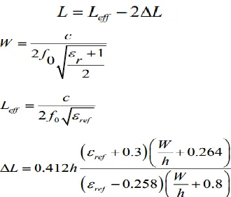
II. DESIGN EQUATIONS
This novel structure consists of three layers. The bottom layer is a metal conductor called as ground plane which covers the complete structure. Its dimensions can be given as [14]
The middle layer consists of dielectric substrate having relative permittivity 4.7, and dielectric loss tangent of 0.0025
. Top of the substrate also consists of metal patch whose dimensions can be given as
The patch antenna is initially designed to operate at 2.24 GHz. The resonance frequency (fr) of the patch is selected to be around 2.4 GHz for the reference antenna design initially. The substrate considered for the antenna is FR-4(Lossy) with dielectric constant,
εr
= 4.7, loss tangent 0.02 and the thickness is 1.6 mm. The thickness of the ground plane(PEC) material is 0.025 mm. The size of the feed line is modified to make sure that the impedance of the antenna is matched at 50Ω.L
EARN
O
BSERVE
D
ECIDE
International Journal of Emerging Technology and Advanced Engineering
Website: www.ijetae.com (ISSN 2250-2459, ISO 9001:2008 Certified Journal, Volume 6, Issue 2, February 2016)
153
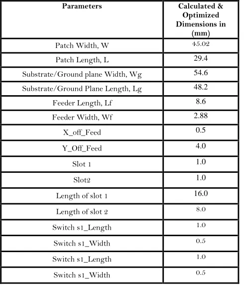
TABLE ITHE SPECIFICATION OF ANTENNA GEOMETRY STRUCTURE OF THE PROPOSED RECONFIGURABLE ANTENNA
REFERENCE DESIGN
Parameters Calculated &
Optimized Dimensions in
(mm)
Patch Width, W 45.02
Patch Length, L 29.4
Substrate/Ground plane Width, Wg 54.6
Substrate/Ground Plane Length, Lg 48.2
Feeder Length, Lf 8.6
Feeder Width, Wf 2.88
X_off_Feed 0.5
Y_Off_Feed 4.0
Slot 1 1.0
Slot2 1.0
Length of slot 1 16.0
Length of slot 2 8.0
Switch s1_Length 1.0
Switch s1_Width 0.5
Switch s1_Length 1.0
Switch s1_Width 0.5
The structure of the proposed reference antenna is as shown below figure 2.
Figure 2:The geometrical structure of calculated dimensions for the reference rectangular micro strip antenna
[image:3.612.48.293.178.464.2]Next, to make the above reference antenna resonating at 2.4GHz into a reconfigurable antenna, resonating at dual bands (2.4GHz, 5.8GHz) two slots and switches are added onto the patch.
Figure.3 shows antenna structure for a reconfiguration of rectangular micro strip slots patch antenna for this investigation.
III. OPTIMIZED RECONFIGURABLE ANTENNA DESIGN
[image:3.612.342.565.380.536.2]A conventional rectangular micro strip patch antenna is first designed and altered to get a required specification at 2.4GHz frequency. This design is used as a reference to design a reconfigurable rectangular micro strip antenna with slots. The parametric study is based on the effects of various dimensional parameters when slots are added to the conventional rectangular micro strip antenna. Two parallel slots are incorporated to perturb the surface current path, introducing local inductive effect that is responsible for the excitation of the second resonant mode. The dimensional parameters of two slot lengths at different spacing from both edges of the antenna will produce a dual band frequency. By optimizing and adjusting the spacing and the slots length, the simulated S11 response is recorded and analyzed.
Figure 3:The geometrical structure of calculated &optimized dimensions for the reference rectangular micro strip antenna with
slots
IV. RESULT AND DISCUSSION
Design and Simulation and measurements were done using EM simulation software MWS with the antenna structure. Two modes were simulated with both switches in 1) OFF mode 2) ON mode. The return loss and VSWR was measured and measured and recorded. The results obtained were tabulated in the following Table II.
International Journal of Emerging Technology and Advanced Engineering
Website: www.ijetae.com (ISSN 2250-2459, ISO 9001:2008 Certified Journal, Volume 6, Issue 2, February 2016)
[image:4.612.324.562.138.324.2]154
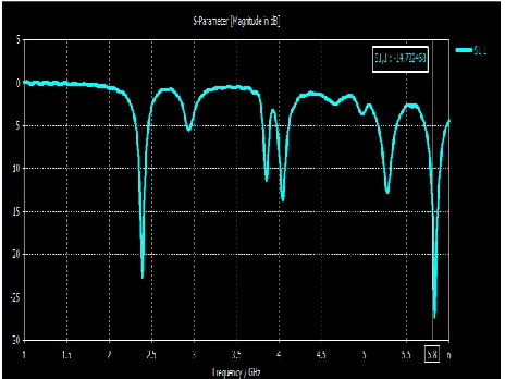
The simulated result will give a result of a single band frequency with the return loss is -19.37 dB at 2.4 GHz, when both switches or in ON state, The antenna structure operates in dual band of frequencies at 2.4GHz and 5.8GHz with a return loss of -18.85 and -14.72 respectively when both switches are in OFF state.TABLE II
RESULTS OF RETURN LOSS(S11) & VSWR
Parameter
Reconfigurable antenna with both switches in OFF
Reconfigurable antenna with both switches in ON
Resonant Frequency
fr1=2.4GHz
fr2=5.8 GHz
fR1=2.4GHz
Return Loss (S11) in dB
S11=-18.85
S11=-14.72
S11=-19.376
VSWR
1.25
1.44
1.24
The following figure III shows a graph of return loss (S11) when both switches are turned OFF. The switch OFF
[image:4.612.44.293.230.391.2]is modeled and simulated by removing the conducting PEC patch to model an ideal turn off condition of RF PIN diode.
Figure 4: Result of S11 parameters when switches is in OFF mode
The following figure IV shows a graph of return loss (S11) when both switches are turned ON. The switch- ON is
modeled and simulated by the PEC patch for RF PIN diode switch to model an ideal turn ON condition.
Figure 5: Result of S11 parameters when both switches are in ON
mode
V. CONCLUSION
A new reconfigurable rectangular slots patch antenna with operating frequencies in the range of WLAN band of (2-6) GHz was designed and simulated ,and radiation characteristics were measured. It has been demonstrated with MWS simulation software and experimental measurement results that the antenna is useful in SDR based WLAN applications.
Future work can be focused on the result of 5.8 GHz as return loss can still be optimized .where the gain is very small compared to 2.4GHz. Besides that, The RF- PIN diode can be replaced with the RF MEMS devices to prevent insertion loss and size of this antenna can also be reduced. The substrate selection can also be suitably selected by conducting optimization.. The permittivity of the substrate affects the size and performances of the antenna.
REFERENCES
[1] FCC, “Report of the spectrum efficiency working group”, FCC spectrum policy task force, Tech. Rep., Nov. 2002.
[2] J. Mitola, “Cognitive Radio: An integrated agent architecture for software defined radio”, Ph.D. dissertation, Royal Institute of Technology (KTH), Stockholm, Sweden, 2000
[3] M. Manteghi, “A switch-band antenna for software defined radio applications”, IEEE Antennas and Wireless Propagation Letters, vol. 8,pp. 3-5, 2009.
[image:4.612.53.285.449.623.2]International Journal of Emerging Technology and Advanced Engineering
Website: www.ijetae.com (ISSN 2250-2459, ISO 9001:2008 Certified Journal, Volume 6, Issue 2, February 2016)
155
[5] B. A. Cetiner, G. R. Crusats, L. Jofre, and N. Biyikli, "RF MEMS Integrated Frequency Reconfigurable Annular Slot Antenna", IEEE Transactions on Antennas and Propagation, vol. 58, no. 3, pag. 626-632, 2010.
[6] C. Zhang, S. Yang, H. K. Pan, A. E. Fathy, S. ElGhazaly, and V. Nair, "Reconfigurable Antenna for Simultaneous Multi-Service Wireless Applications", Radio and Wireless Symposium, 2007 IEEE, 2007, page. 543-546.
[7] C. R. White, and G. M. Rebeiz, "A Shallow Varactor-Tuned Cavity-Backed Slot Antenna With a 1.9:1 Tuning Range", IEEE Transactions on Antennas and Propagation, vol. 58, no. 3, page. 633-639, 2010.
[8] S. Baylis, S. Aguilar, and T. Weller, "Wide bandwidth varactor-tuned patch antenna", Electronics Letters , vol.45, no.16, pp.816 − 818, July 2009
[9] J. R. De Luis, and F. De Flaviis, «Frequency Agile Switched Beam Antenna Array System», IEEE Transactions on Antennas and Propagation, vol. 58, n. 10, pag. 3196-3204, 2010.
[10] P.-Y. Qin, A. R. Weily, Y. J. Guo, T. S. Bird, and C.-H. Liang, "Frequency Reconfigurable QuasiYagi Folded Dipole Antenna", EEE Transactions on Antennas and Propagation, vol. 58, no. 8, page. 2742-2747, 2010.
[11] F. Yang, and Y. Rahmat-Samii, "Patch antennas with switchable slots (PASS) in wireless communications: concepts, designs, and applications", IEEE Antennas and Propagation Magazine, vol. 47, n. 2, page. 13-29, 2005.
[12] J.-H. Lim, G.-T. Back, Y.-I. Ko, C.-W. Song, and T.-Y. Yun, "A Reconfigurable PIFA Using a Switchable PIN-Diode and a Fine-Tuning Varactor for USPCS/WCDMA/mWiMAX/WLAN", IEEE Transaction on Antennas and Propagation.
[13] C. Zhang, S. Yang, S. El-Ghazaly, A. E. Fathy, and V. K. Nair, "A Low-Profile Branched Monopole Laptop Reconfigurable Multiband Antenna for Wireless Applications", Antennas and Wireless Propagation Letters, IEEE, vol. 8, pag. 216 − 219, 2009.
[14] K. R. Boyle, et al., “Reconfigurable Antennas for SDR and Cognitive Radio,” Proceedings of the 2nd European Conference on ntennas and Propagation, Edinburgh, 11-16 November 2007, pp. 1-6. [15] C. A. Balanis, “Antenna Theory – Analysis and Design”,