Performance Comparison of Different FRP
Wrapped Hollow Circular Steel Column
under Different Loading Conditions
Krishna P Rajan1, Reshma Babu2
M. Tech Scholar, Jai Bharath Collage of Management & Engineering Technology, Arakkappady, Kerala, India1
Assistant Professor, Jai Bharath Collage of Management & Engineering Technology, Arakkappady, Kerala, India2
ABSTRACT: In the steel construction industry, tubular structures become typically used due to their structural efficiency and economical values. So, rehabilitation and restoration of these structures are essential to maintain or increase its load carrying capacity and hence it’s structural performance. FRP is the common method of strengthening the structures for the last two decades. The most widely used FRP composites are glass fibre reinforced polymer (GFRP) composites, Aramid fibre reinforced polymer (AFRP) and carbon fibre reinforced polymer (CFRP). This thesis involves comparing and studying about the maximum load carrying capacity of circular hollow steel columns when they are wrapped with different FRP’s using Ansys workbench 15.0. FRP’s are wrapped at different locations of the columns at different percentages ie., covering ½ , 1/3 and ¼ surface area of the column. Also layers of the FRP’s are also changed and maximum load carrying capacity is obtained for each cases.
KEYWORDS: Circular hollow steel (CHS) column, axial loading, lateral loading, cyclic loading, ATC-24, IS 1161: 1998 T-1, GFRP wrapping, CFRP wrapping, AFRP wrapping.
I. INTRODUCTION
than any open section profiles; the overall weight saving that can be gained by using them will, very often, result in much more cost effective and so economic construction.
The main objective of this project is as follows:
• To calibrate the failure load of specimen under the axial loading.
• To model an existing building and taking that load into consideration for designing hollow steel column..
• To conduct the study on the effect of different FRP wrapping on specimen using Ansys Workbench 15.0.
• To compare the performance of different FRP wrappings on the specimen at different locations
• To study the effect of different FRP’s wrapped at different percentages and different layers
• To study the effect of different FRP’s under different loading conditions.
The scope of work involves finding the effectiveness of FRP wrappings over hollow steel columns. It also involves comparative study of performance of different types of FRP wrappings on the hollow steel columns at different locations under different loading conditions. From this study, the most effective type of FRP and its most effective location can be founded.
II. VALIDATIONOFCOLUMN
To verify the FEM software, study conducted by Guo et al. “Behaviour of thin walled circular hollow section, stub columns under axial compression” was selected. In this literature, both experimental and analytical work were done to determine the structural performance of hollow steel stub column. The experiment part of that study was validated by ANSYS WORKBENCH 15.0 using the material properties and specimen specification noted in that journal. Size of hollow steel column from journal: Height of column = 1800 mm, Diameter = 600 mm, Thickness = 2 mm. The maximum load obtained while validation is 177kN. In the journal the value of maximum load is 190kN. Thus the percentage variation of maximum load is almost 7% compared with the journal.
III. MODELINGANEXISTINGBUILDINGINETABS
An existing residential building proposed for Mr. Kasim, in survey no: 104/7-2, Edappally north is choosen. It is a G+5 building. This building is then modeled in ETABS. Then loads acting on each columns are obtained. For further proceeding of project work, the column carrying maximum load is to be selected. Maximum load of the column obtained from etabs is 1433kN. It is the maximum load acting on the column. Taking this load into consideration we can fix a size for the hollow steel column using steel code.
IV. MAXIMUMLOADCARRYINGCAPACITYOFHOLLOWSTEELCOLUMN
An existing residential building is modeled in Etabs and the column carrying maximum load is obtained. This concrete column is then replaced with circular hollow steel column and then the maximum load carrying capacity of the circular hollow steel column is obtained using ANSYS WORKBENCH 15.0.
Size of circular hollow steel column:
Area of steel column = (from steel code)
= . . = 81.55 cm2 From IS 1161 : 1998 T-1
RESULT: Maximum load carrying capacity of hollow steel column of size 350 mm diameter and 8 mm thickness without FRP wrapping is 1450 kN. Normal stress value obtained is 188.34 Mpa. Stiffness of the column is 99.72 kN/mm.
V. LOADCARRYINGCAPACITYOFCOLUMNWRAPPEDWITHDIFFERENTFRP’SUNDERAXIAL,
LATERALANDCYCLICLOADING
The hollow steel column is modeled in Ansys workbench 15.0. Firstly in engineering data section, hollow steel is added as a new material. Model the column in geometry section of Ansys. Size of the column is 350 mm diameter, 2250 mm length and thickness is 8 mm. Table 2 shows properties of GFRP and Table 3 shows the specifications of FRP and based on these specifications columns are designed.
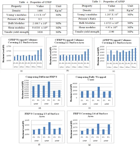
Fig 1 Graphs for Axial Loading (a) Maximum Load of GFRP Columns, (b) Maximum Load of CFRP Columns, (c) Maximum Load of AFRP Columns, (d) Comparing Different FRP’s at 5 locations, (e) Comparing Fully Wrapped Cases of Different FRP’s, (f) Comparing FRP’s Covering 1/3
of Surface Area, (g) Comparing FRP’s Covering ¼ of Surface Area
carrying capacity is shown by column wrapped with CFRP with 4 layers. Fig 1 (f) & (g) shows that maximum load is taken by columns wrapped with GFRP. GFRP’s with 4 layers show more load carrying capacity than 2 layers. After GFRP, AFRP with 4 layers show maximum load carrying capacity. AFRP carries 1674 kN and GFRP carries 1675kN of load. There is only a negligible difference between load carrying capacity of these two FRP’s.
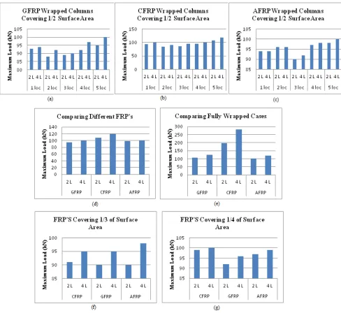
Fig 2: Graphs for Lateral loading (a) Maximum Load of GFRP Columns, (b) Maximum Load of CFRP Columns, (c) Maximum Load of AFRP Columns, (d) Comparing Different FRP’s at 5 locations, (e) Comparing Fully Wrapped Cases of Different FRP’s, (f) Comparing FRP’s Covering 1/3 of Surface Area, (g) Comparing FRP’s Covering ¼ of Surface Area
taken by CFRP wrapped columns when CFRP is wrapped at 5 different locations. Maximum lateral load carried by CFRP wrapped column is 119kN and it is at 5 locations.
Fig 2 (d) clearly shows that CFRP has maximum load carrying capacity than AFRP and CFRP. Its also clear that CFRP with 4 layers carry more load than CFRP with 2 layers.
Fig 2 (e) shows the comparison between different FRP’s when they are fully wrapped around the column. In this also maximum load is taken by CFRP wrapped with 4 layers and the value is 282kN. For CFRP with 2 layers value of maximum load is 197 kN. CFRP shows increase in load carrying capacity when layers are changed but all other FRP’s do not show much load increment.
Fig 2 (f) shows clearly that maximum lateral load is taken by column wrapped with AFRP. Fig 2 (g) shows that maximum load is taken by columns wrapped with CFRP, followed by AFRP and then by GFRP. There is very negligible difference in load carrying capacity of columns with CFRP when the layers are changed. Also we can see that, the difference in load of AFRP and CFRP is also very negligible. From both the above figures, we can also conclude that AFRP covering ¼ surface area have more lateral load carrying capacity than CFRP covering 1/3 of surface area, when both FRP’s are provided at 4 locations.
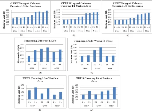
Fig 3: Graphs for Cyclic loading (a) Maximum Load of GFRP Columns, (b) Maximum Load of CFRP Columns, (c) Maximum Load of AFRP Columns, (d) Comparing Different FRP’s at 5 locations, (e) Comparing Fully Wrapped Cases of Different FRP’s, (f) Comparing FRP’s Covering 1/3
Fig 3 (a), (b) & (c) shows that maximum load is taken by FRP’s which are wrapped at 5 different locations. Similar results is shown by FRP’s wrapped at 1/3 and ¼ of surface areas. It’s also clear that maximum load is carried by CFRP wrapped column and it is at 5 locations. From Fig 3 (d) we can see that maximum load is taken by columns wrapped with CFRP followed by AFRP and GFRP. Difference between AFRP and GFRP is very very small. Fig 3 (e) shows the comparison between different FRP’s when they are fully wrapped around the column. In this also maximum load is taken by CFRP wrapped with 4 layers. Fig 3 (f) shows that maximum cyclic load is taken by column wrapped with CFRP and GFRP. Both are carrying loads of 176.53 kN and 176.03 kN respectively. This values is almost same so we can say that both the FRP’s have same load carrying capacity. Fig 3 (g) shows the graph comparing maximum cyclic load carrying capacity of columns with FRP’s Covering ¼ of Surface Area. In this case maximum load is taken by columns wrapped with AFRP, followed by CFRP and then by GFRP. Also we can see that, the difference in load of GFRP and CFRP is also very negligible.
VI. RESULTSANDDISCUSSION
When CFRP is fully wrapped around the hollow steel column its load carrying capacity increases from 1450kN to 1835 kN for 2 layers CFRP. As original load carrying capacity of this hollow steel column without FRP is 1450 kN , about 27 % of increase in load carrying capacity is obtained.
For fully wrapped condition only we can see an increment in load carrying capacity of columns wrapped with 2 layers and 4 layers. There is an increment of about 67% for columns wrapped with 4 layers of CFRP than those with 2 layers.
For fully wrapped condition only we can see an increment in load carrying capacity of columns wrapped with 2 layers and 4 layers. There is an increment of about 97% for columns wrapped with 4 layers of CFRP than those with 2 layers.
At 1/3 and ¼ surface area maximum axial load is taken by columns wrapped with GFRP. GFRP’s with 4 layers show more load carrying capacity than 2 layers. After GFRP, AFRP with 4 layers show maximum load carrying capacity. AFRP carries 1674 kN and GFRP carries 1675kN of load.
Maximum lateral load is taken by column wrapped with AFRP when 1/3 of surface area is covered. But when 1/4th surface area is covered, maximum load is taken by columns wrapped with CFRP, followed by AFRP and then by GFRP
AFRP covering ¼ surface area have more lateral load carrying capacity than CFRP covering 1/3 of surface area, when both FRP’s are provided at 4 locations.
When wrapped 1/3 surface area, maximum cyclic load is taken by column wrapped with CFRP and GFRP. Both are carrying loads of 176.53 kN and 176.03 kN respectively.
Maximum cyclic load is taken by columns wrapped with AFRP, followed by CFRP and then by GFRP when
they cover ¼ surface area. Also we can see that, the difference in load of GFRP and CFRP is also very negligible.
VII. CONCLUSION
From all of the above obtained values of hollow steel column wrapped with FRP’s under different loading, we can see maximum load carrying capacity is for CFRP wrapped columns.
When the percentage of FRP is varied like ½ , 1/3, ¼ of surface areas of hollow steel column, maximum load carrying capacity is obtained columns wrapped around ½ the surface area. For all FRP’s maximum load is obtained for those covering ½ of the surface area of hollow column.
When FRP’s are provided at different locations, maximum load carrying capacity is obtained for those wrapped at 5 different locations.
Maximum axial load is obtained for GFRP, when it covers about 1/3 and ¼ surface area of steel column. This is obtained when they are wrapped at 5 locations.
Maximum lateral load is obtained for AFRP when it covers 1/3 surface area of column. Also maximum lateral load is obtained for CFRP when it covers ¼ surface area of column.
Maximum cyclic load is obtained for CFRP and GFRP when they are wrapped at 1/3 surface area of column. When ¼ of the surface area of steel column is covered with FRP, then AFRP carries maximum cyclic load.
While comparing stiffness, it’s more for AFRP ,followed by CFRP and then GFRP. As GFRP has low stiffness, it’s more flexible and can be used in seismic prone areas.
REFERENCES
[1] Treesa Tintu, Merin T Saji ( MAY 2018 ) ”Influence Of Gfrp Wrapping On Defecient Hollow Circular Steel Column Under Cyclic Loading” International Research Journal of Engineering and Technology (IRJET) Volume: 05 Issue: 05
[2] Sharanya V.S., Nikhil R. ( APRIL 2018 ) “Experimental Study on Behaviour of Concrete Filled Steel Tubular Columns” International Journal of Scientific & Engineering Research Volume 9, Issue 4, April-2018
[3] Ridha M S ( MAY 2017 ) “Axial-Flexural Interaction of Square FRP Tube Columns In-Filled with Ultra-High Performance Concrete” Polymer Sciences ISSN 2471-9935, Vol 3, No:13
[4] Cheng Huang,Tao Chen and Xian Wang(2017), “Compressive characteristics of damaged circular hollow section (CSH) steel columns repaired by CFRP or grout jacketing”, Thin-Walled Structures, 119:635-645
[5] Masoumeh Karimian, Kambiz Narmashiri, Mehdi Shahraki, and Omid Yousefi (2017), “Structural behaviors of deficient steel CHS short columns strengthened using CFRP”, Journal of Constructional Steel Research,138: 555–564
[6] Lili Hu, Peng Feng and Xiao-Ling Zhao(2017), “Fatigue design of CFRP strengthened steel members”, Thin- Walled Structures,119: 482-492 [7] Weiwei Lin, Nozomu Taniguchi and Teruhiko Yoda(2017),”A preventive strengthening method for steel columns: Experimental study and
numerical analysis”, Journal of construction steel research,138: 357-368
[8] Lanhui Guo, Yong Liu, Hui Jiao, and Shilong An ( SEPTEMBER 2016 ) “Behavior of Thin-walled Circular Hollow Section Stub Columns Under Axial Compression” International Journal of Steel Structures 16(3): 777-787 (2016)
[9] Ou Zhao, Leroy Gardner and Ben Young(2016), “Structural performance of stainless steel circular hollow sections under combined axial load and bending” -Part 2 :Parametric studies and designs, Thin walled structures, 5: 127-138
[10] Junfeng Jia, Qiang Han, Zigang Xu, and Dongjie Zhang ( OCTOBER 2014) “Cyclic Load Responses of GFRP-Strengthened Hollow Rectangular Bridge Piers” Urban Security and Disaster Engineering of Ministry of Education, Beijing University of Technology, No. 100 Pinleyuan, Beijing 100124
[11] Chen Chen, Yinghua Zhao and Jackie Li (2014), “Experimental investigation on impact performance of concrete filled FRP steel tubes”, Journal of Engineering Mechanics, 11:04014112
[12] J.G. Teng, T. Yu and D. Fernando (2012), “Strengthening of steel structures with fiber reinforced polymer composites”, Journal of constructional steel research, 78:131-143
[13] Yoshiaki Goto, Kunsheng Jiang and Makoto Obata(2006), “Stability and ductility of thin walled circular steel columns under cyclic bidirectional loading”, Journal of Structural Engineering,132:1621-1631.
[14] Yan XIAO, Wenhui HE , Xiaoyong MAO, Kang-Kyu CHOI, Shouping SHANG, Yurong GUO ( AUGUST 2004 ) “Experimental Studies Of Confined Concrete Filled Steel Tubular (CCFT) Columns” 13th World Conference on Earthquake Engineering Vancouver, B.C., Canada August 1-6, 2004 Paper No. 681
[15] Minoru Yamashita, Manabu Gotoh and Yasuhiko Sawairi(2003), “Axial crush of hollow cylinder structure with various polygonal cross sections numerical simulation and experiment”, Journal of material processing technology, 140: 59-64